Page 1958 of 3115
2004 LAND CRUISER (EWD548U)
19 E
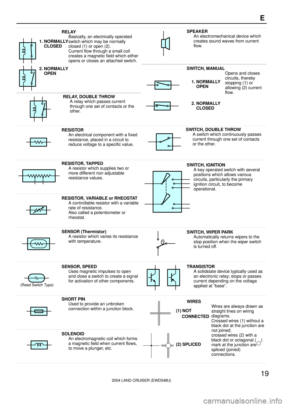
RELAY
Basically, an electrically operated
switch which may be normally
closed (1) or open (2).
Current flow through a small coil
creates a magnetic field which either
opens or closes an attached switch.
1. NORMALLY
CLOSED
2. NORMALLY
OPEN
SWITCH, MANUAL
Opens and closes
iitth b
SPEAKER
An electromechanical device which
creates sound waves from current
flow.
RELAY, DOUBLE THROW
A relay which passes current
through one set of contacts or the
other.
circuits, thereby
stopping (1) or
allowing (2) current
flow.1. NORMALLY
OPEN
2. NORMALLY
CLOSED
RESISTOR
An electrical component with a fixed
resistance, placed in a circuit to
reduce voltage to a specific value.SWITCH, DOUBLE THROW
A switch which continuously passes
current through one set of contacts
or the other.
RESISTOR, TAPPED
A resistor which supplies two or
more different non adjustable
resistance values.SWITCH, IGNITION
A key operated switch with several
positions which allows various
circuits, particularly the primary
ignition circuit, to become
operational.
RESISTOR, VARIABLE or RHEOSTAT
A controllable resistor with a variable
rate of resistance.
Also called a potentiometer or
rheostat.
SENSOR (Thermistor)
A resistor which varies its resistance
with temperature.SWITCH, WIPER PARK
Automatically returns wipers to the
stop position when the wiper switch
is turned off.
(Reed Switch Type)
SENSOR, SPEED
Uses magnetic impulses to open
and close a switch to create a signal
for activation of other components.TRANSISTOR
A solidstate device typically used as
an electronic relay; stops or passes
current depending on the voltage
applied at ºbaseº.
SHORT PIN
Used to provide an unbroken
connection within a junction block.WIRES
Wires are always drawn as
straight lines on wiring
diagrams.
Crossed wires (1) without a
black dot at the junction are
tj i d
(1) NOT
CONNECTED
SOLENOID
An electromagnetic coil which forms
a magnetic field when current flows,
to move a plunger, etc.
j
not joined;
crossed wires (2) with a
black dot or octagonal ( )
mark at the junction are
spliced (joined)
connections.
(2) SPLICED
Page 1968 of 3115
2004 LAND CRUISER (EWD548U)
M OVERALL ELECTRICAL WIRING DIAGRAM
1
234
1 LAND CRUISER(
Cont. next page)
2A 1C 1A 1B
7. 5A AM1
2C 12E 39
1 2
5 3
1 2
5 3
2E 40
IFSet Bolt of Cowl Side
J/ B LH
7. 5A ACC2Q 57
10A GAUGE1
2Q 65 2E37 2Q772
7ACC
IG1
IG2
ST 2 AM13
4
6 AM2
6B 5
6D 26B 4
6D 3
4IX1
A A
3E 4 3Q 50 3Q51
3 4
2 1
1 2
3 5 3Q 39 3C1
7. 5A
SECURITY 20A P/ W (
FR)
3E 16 2
IISet Bolt of Cowl Side
J/B RH 3Q 52
3IX1
Bat tery
B- GB- GB- R L- BSBB- R
I18
B- R
SB B
IG1
NO. 3
Re la y ACC
CUT
Relay
SB
B- R
SB B- G
B- R
ACC Relay
120A
MAI N120A
J/B
NO. 3120A
J/B
NO. 1
140A
AL T120A
J/B
NO. 2
F1 5(
A)
, F16(
B)
, F17(
C)
B- G
B- G 10A ECU- I G1
2I 1 2Q 21
3 5
2 1
4
20A
DEFOG
IG1
NO. 2
Re la y
2D 24
7. 5A IDLE UP
2G 2
DE FOG Rel a y
3Q 7 3I 13E13K37 3E33
7. 5A MET
10A GAUGE220A P/W (
FL) 20A P/W (
RR) 20A P/W (
RL)
L
M
N
O
P A
B
DC
E
F
G
IH
K A A
LGL
L
L
L SB
SBB
SB
B- W
SB
SB
B- R
W- RL- BB
Rear Window
Defogger Sys tem
<11- 2>
J14J 4
Engine Contr ol
System< 4- 2>
L
L
SB
L L LG W- RB SB B- WSB SB B- G B- G
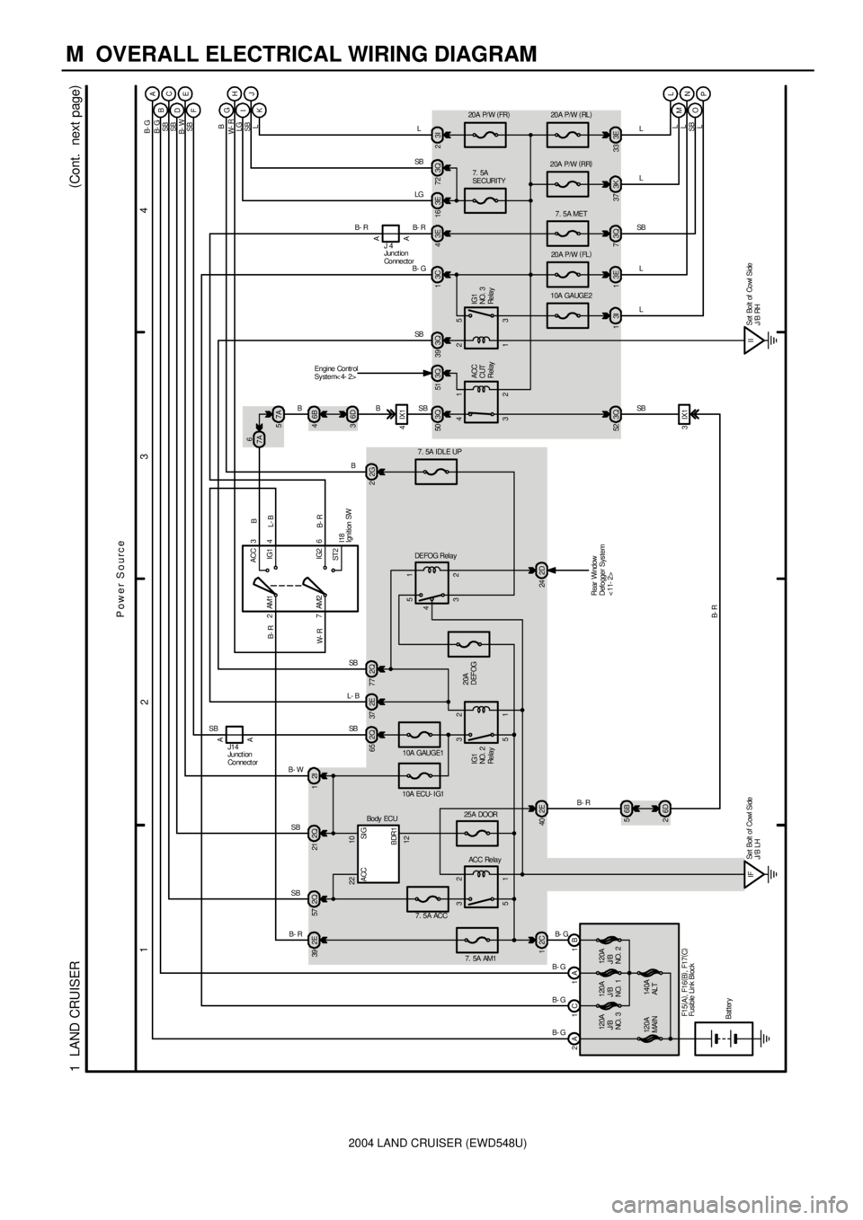
Power Source
3Q 72 3I
L
J
SB
SB
B- R
Ignition SW
Junction
Connector
Fusible Link Block
Junct ion
Connect or
25A DOOR
22 10
12SI G ACC
BDR1
Bo dy ECU B
6
7A
7A 5
Page 1970 of 3115
2004 LAND CRUISER (EWD548U)
M OVERALL ELECTRICAL WIRING DIAGRAM
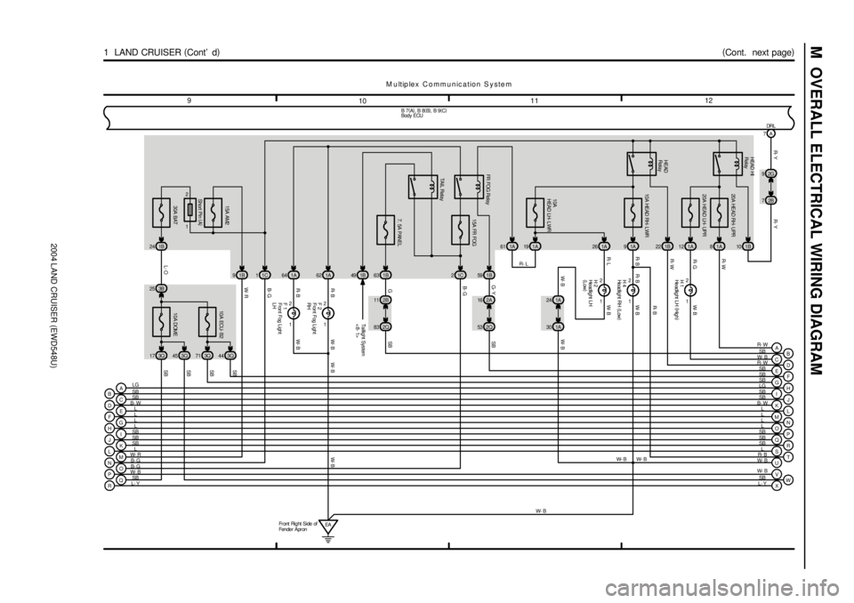
M u ltip le x C o m m u n ic a tio n S y s te m
1112
10 9
(
Cont. next page)
1 LAND CRUISER (
Cont' d)
10A
HEAD LH- LWR
1A
1 2
10A HEAD RH- LWR
1A
20A HEAD RH- UPR
1A
H 2
1
2H 4
1
2H 1
R- L R- BR- G
A
B
C
D
E
F
G
H
I
J
K
L
M
N
O
P
Q
RLG
SB
SB
L
L
L
L
SB
SB
SB
L
W- R
B- G
B- G
W- B
SB
L- YB 7(
A)
, B 8(
B)
, B 9(
C)
F
G
H
I
J
K
L
M
N
O
P
Q
R
S SB
SB
LG
SB
SB
L
L
L
L
SB
SB
L
R- B
T
W- B 26 9 8
1 2
F 1
1
2F 2
R- B R- B
W- BEA Fr ont Right Side of
Fender ApronW- B W- B
1A 64 1A62 2
1 5A FR FOG
1C 1B591A 61 1A19
2A 16
2Q 53
FR FOG Rel a yG- Y SB
R- L
R- B
B- W1C 1
15A AM2
1B 9
30A BAT
1B 24
10A DOME 10A ECU- B2
3Q 17 3Q45 3Q71 3Q44 3B 25
E SBD R- WC W- B
U
V
W
X W- B
SB
L- Y 1B 22 1B107A
2G 9
2B 7
SB B- W
R- Y R- Y
R- W
W- B W- BR- B W- B
W- B
B- G
B- G
W- R
L- OSB
SB
SB
SB
W- BW- B W- B
Short Pin (
A)W- B HEAD HI
Relay
HEAD
Relay
DRL
1 2
TAIL Rel a y
7. 5A PANEL
1B 49 1B63
1A 24
1A 30
W- B
B
Taillight System
<8- 1>
SB
G2B 11
2Q 83SB
Front Fog Light
LH Front Fog Light
RH Headlight LH (
High)
Headlight LH
(
Low) Headlight RH (
Low)
Body ECU
12
20A HEAD LH- UPR
1A
A
R- W
R- W
Page 1972 of 3115
2004 LAND CRUISER (EWD548U)
M OVERALL ELECTRICAL WIRING DIAGRAM
1920
18 17
(
Cont. next page)
1 LAND CRUISER (
Cont' d)
1
T 1
114 C
21026 C
1 2
U 1
SH-WSB
KSW +B1 IG MPX1KSW MPX3
R- B
BR- B R- B W- B
T 5
QP ON ML KJ IH GF EDR- Y
SB
SB
LG
SB
B- W
L
L
L
L
SB
SB
SBB 7(
A)
, B 8(
B)
, B 9(
C)
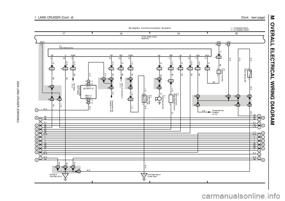
M u ltip le x C o m m u n ic a tio n S y s te m
E
F
I
J
K
M
N
O
P L SB
L- W
L
L
L
SB
SB
SB
SRL
L- Y
Q W- B
TW- B
R
S W- B
SB
SB
SB
J14
E
E 1IL315 I U3
3E 18 3E23
SB
G
H
L D
B- WL- Y R- Y
L
IF Se t Bol t of
Cowl Side J /B LH2Q 20 2L 11 2I83P 3
3P 1 22 IL3
VUW- B
SB12 IL3
2Q 222Q 26
2I 28IL3
3Q 82
3B 4
18
2E 6IL3
6 EA2
2 1 5IL3
EAFront Right Side of
Fender Apron7IL3
3B 63Q 843IL3
14 IU314 IL3 15 IL3 9 IL3 20 IL3
3Q 74
3E 2531 12 11 34 23 25 5 29 3
2 1 GBS DSWH RE V IND HORN E +B 2
W- BR- B
B W- BG- OG- RB L- B Y- GLG B- WR- BB
SB Y- G LG SB
SB SB
W
SB L- B L- BW- B
SB
SB
SB
SB SB
SB L- W
W- BSB W- B W- B
BECU
11
Ho r n Re la y
<18- 4> Data Link Connec tor 3
<4- 7>E 3
W- B
Transponder Key
Computer
<4- 19>
Z 1
L- B
C B
CB
SB SB
SB SB 3Q 76
3E 27 3D 12
14 B(
*2) 21 A(
*1)
3A(
*1)
8B(
*2)
A
Transponder Key
Computer< 4- 20>
G- RG- R
G- R W- B
LP(
*1)
SECURITY(
*2)
GND(
*2) GND1(
*1)
M 5(
A)
, M 9(
B)
W- B* 1 : w/ Nav igation Sy st em
* 2 : w/o Navigation System
3Q 46
A SB
Engine Hood
Courtesy SW
Multi- DisplayTheft Deterrent Horn
Theft Deterrent ECU
Un lo ck War ni ng SW
Bo dy ECU
Junct ion Connector
Option Connect or
(
Glass Breakage Sensor)
Page 1974 of 3115
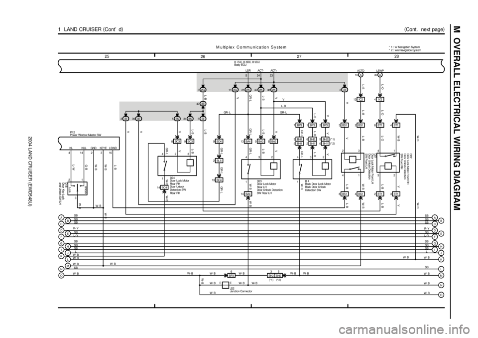
2004 LAND CRUISER (EWD548U)
M OVERALL ELECTRICAL WIRING DIAGRAM
2728
26 25
(
Cont. next page)
1 LAND CRUISER (
Cont' d)
V L- BGR - L V
GR- L
V L- BV
L- B
ACTDL- B
L- B L- B
D2 3 23 53K 343K
BC3 8BC39
BC4 132 3 432I 38 2K 42 2K
BA3 8 BA3 9 BA4 13A 10
23BS1 3IC2 13
D
E
F
G
HR- Y
SB
L- Y
SB
SB
M u ltip le x C o m m u n ic a tio n S y s te m
B 7(
A)
, B 8(
B)
, B 9(
C)
D
E
F
G
H
I R- Y
L- Y
SB
SB
SB 25 2K
V
GR- L
2BL5 9BD4
GR- L GR- L V
L- B
GR- L
GR- LL- BV
2BS1
L- B
V
L- B
16
4 3E 422G 3
L- B
I
JSB
L
W- B W- B
L K
MW- B
W- BSB
ONJ
K
L SB
M W- BSB
L
W- B
G- B
L- W
414D1 8
4BS1 8BS1 3
W- B
2W- B
3I 5 3E 39
V
GR - LL- B
B 42 3 4 7BP3 1BP3 2BP3 2G 11
3I 3
L- OIY2 4
8BT1
4L- O
2BT1 3BT1LSWP
L- OA 30
132 52423LSR ACT- ACT+
W- B
W- B W- B
V
L- B
GR- L
V
V
W- B L- B W- BL- BV
L- B W- BL- BV W- B
W- B
P12
L- B
14 BA4
N W- B E 14 BC4
E BP36
W- B W- B
W- B GR- L W- B L- BV
W- B W- B W- B
W- B W- B W- B W- B W- B 1
1 1 D2 4
D21 D22
J22 GR - L
V
O W- B W- B
Un l oc k
Lock
3 21
B
CB
C SB SB
SB SB 4
W- B
AA SB
SB KL KUL GND KEYE LSWD
Back Door Lock Motor
B ack Do or Un l ock
Detection SWDo or Ke y L oc k
and Unloc k SW LH Door Lock Motor Front LH
Door Unlock Detect ion
SW Fr ont LH Door Unlock Detect ion
SW Fr ont RH
Do or L oc k Mo t or
Re ar L H
Door Unlock Det ection
SW Rear LH Door Loc k Motor
Re ar RH
Do or Unl o ck
De t ec t i on S W
Re ar RH Power Window Mast er SWBody ECU
Junction Connector
W- B Door Lock Motor Front RH
1 4BT1W- B W- B
5BH1BH1 3
2BH1BH2 6
6BH1BH2 5(
*1)
(
*2)
BH25 3
BH2
(
*2) (
*1)* 1 : w/ Nav igat ion Sys tem
* 2 : w/o Nav igation Sy st em
Page 1976 of 3115
2004 LAND CRUISER (EWD548U)
M OVERALL ELECTRICAL WIRING DIAGRAM
3536
34 33
(
Cont. next page)
1 LAND CRUISER (
Cont' d)
M u ltip le x C o m m u n ic a tio n S y s te m
A
H B
IX1 8 C
F
G
EC I EB 7(
A)
, B 8(
B)
, B 9(
C)
SB
1
10 D12DA
Do or Beam BRAKE
13 D 14 D 7 A 10 D 3 A 5 A 8B
11D 19 C IU3
R- Y
3DCY2
C 11
SB
SB
SB18 C 20 D
D
SB
SB SB1D SB
SB
SB
SB
SBSB
SB SB
SBSB
SB
SB
SB SB
SB
SB
SB
3EG- Y
19DRL P
C 12
3Q 9
SB
9D
SB
ASB
B SB 2Q
R- W
P 8
31
1 27 2K42B 29 2Q
SB
2ER- W
14PKB
B 2
2Q 37
3D 7 23Q
R- W SB SB R- W
ABS & BA & TRAC & VSC
ECU< 12- 9>
Multi- Display
< 26- 15>
SB
Park ing Br ak e SW
Bo dy ECU
C12(
A)
, C13(
B)
, C14(
C)
, C15(
D)
Combination MeterBu zz er
Rear Bank of
Right Cy linder Head
Page 1978 of 3115
2004 LAND CRUISER (EWD548U)
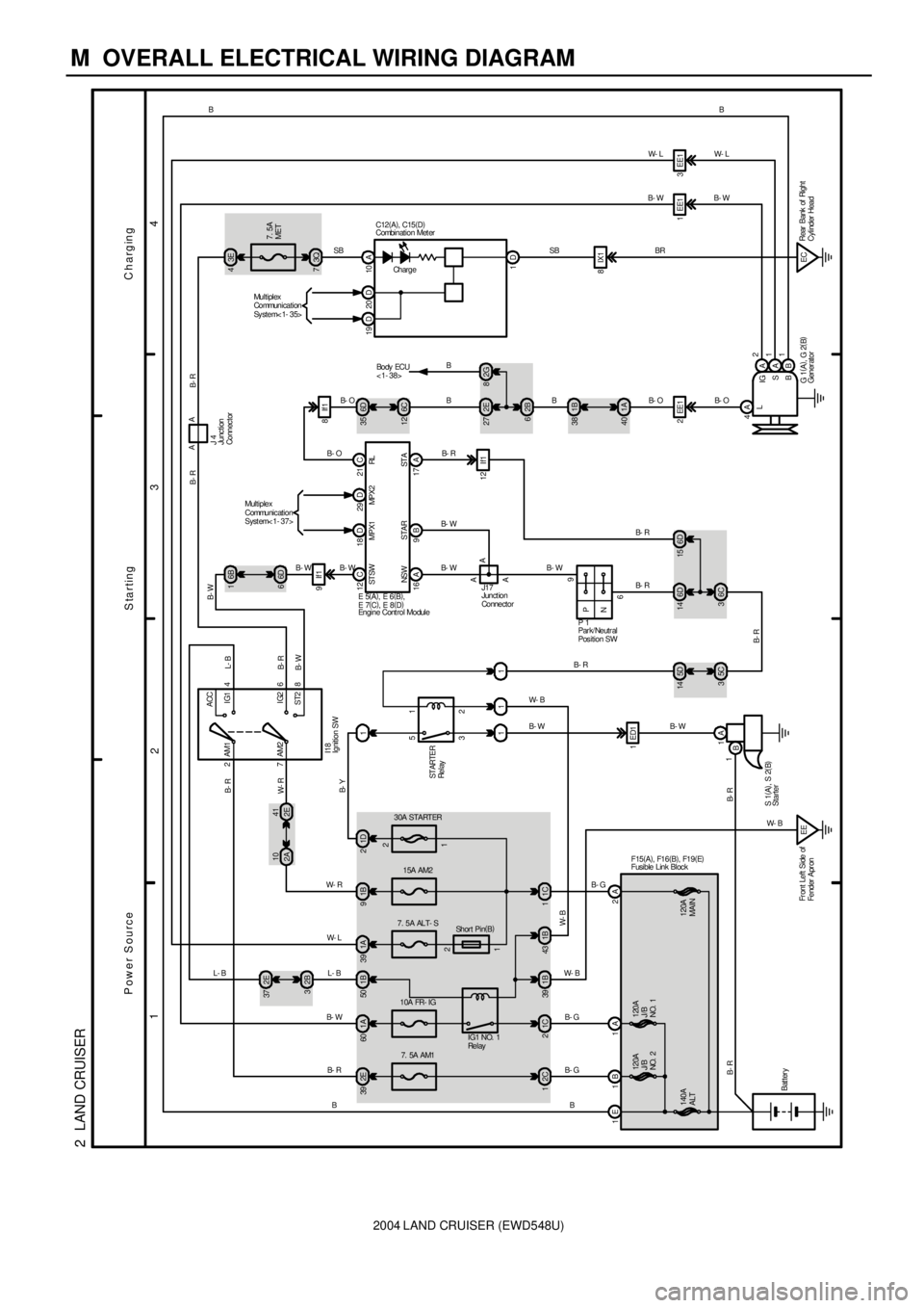
M OVERALL ELECTRICAL WIRING DIAGRAM
1
234
2 LAND CRUISER
140A
ALT2C
1
7. 5A AM1
2E 39B- G
B
1A 60
15A AM2 30A STARTER
1B 9
1C
Bat teryAM2 7
8 6 4 AM1
ST2IG2 IG1 ACC
2
2 1
3 5
11
1A
B1ED1
16
SB
9
P
N3E 4
7. 5A
MET
3Q 7
2E 27
62B
1B 38
40 1A
2EE1
4A
L
A2
A
B IG
S
B1EE1 3EE1
Charging
Starting Power Source
B- R
W- RL- B
B- R
B- W
B- R B- R
B- W
B- R
B W- RB- GB- W B- R B- W B
BB-OB- WW- L
B- O B- WW- LB
ST ARTER
Re l ay
1 1 11 2
120A
J/B
NO. 2120A
J/B
NO. 1 1E 1B 2A1A1C 2
B- G
1A 39
7. 5A ALT- S
IG1 NO. 1
Re l ay
1B 50
10A FR- IG
41
2E 10
2A
Sh or t Pi n(
B)
I18
S 1(
A)
, S 2(
B) 1B 39 1B43
EE
F15(
A)
, F16(
B)
, F19(
E)
1
Fr ont Left Side of
Fender Apr on1D 21B- Y 2B 32E 37
L- B W- L
L- B
6D 66B 1
6D 14
6C 36D 15
P 1
A A 12 C
16 A 9 B 17 A21 C
E 5(
A)
, E 6(
B)
,
E 7(
C)
, E 8(
D)
6D 35
6C 12
B- O
B- W B- WB- RB C12(
A)
, C15(
D)
J17
A
B- R
B- W W- BB- R
W- B
W- B
G 1(
A)
, G 2(
B) ST SW
NS W S TA R ST ARL10 A
1D
W- B
5D 14
5C 3
B- RAA
J 4 B- R B- R
120A
MAIN 1 2
SBEC 8IX1BR
Ch ar g eRear Bank of Right
Cylinder Head 2G 8
B
Bo dy ECU
< 1- 38> Combination Meter
Engine Cont rol ModuleGener ator Ignition SW
Park/ Neutral
Position SW
Starter
Junction
Connector
Junc tion
Connec tor
Fusible Link Block
29 D 18 DMultiplex
Communication
Syst em< 1- 37>
20 D 19 DMultiplex
Communication
Sy st e m< 1- 3 5>
MPX2 MPX1
B- W B- W
B- W
B- O
9If1
8If1
12 If1
Page 1980 of 3115
2004 LAND CRUISER (EWD548U)
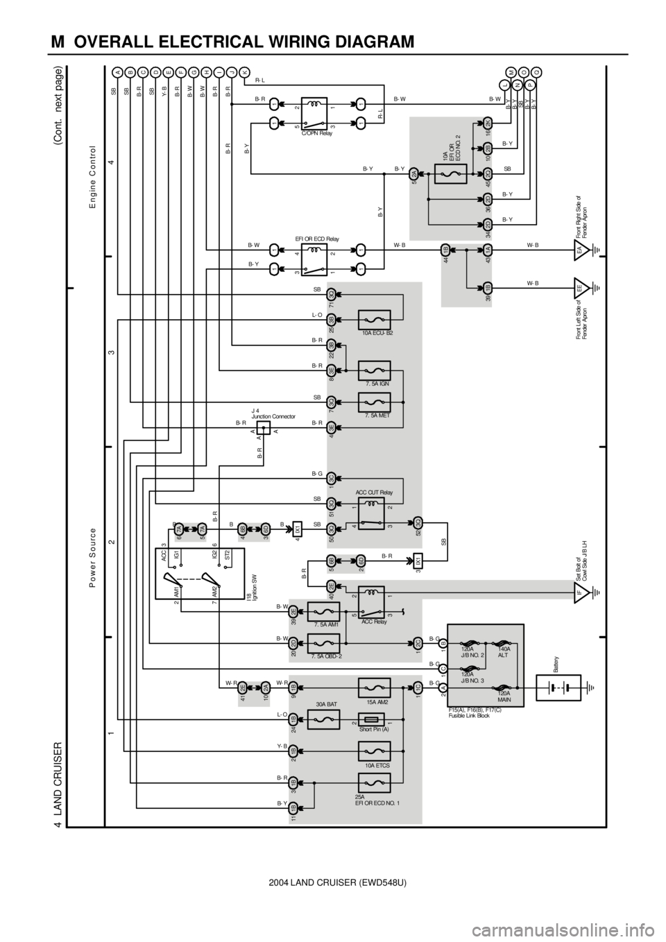
M OVERALL ELECTRICAL WIRING DIAGRAM
1
234
4 LAND CRUISER(
Cont. next page)
2A 1B
Battery
B- G B- G1C 12C1
15A AM2
30A BAT
1B 24 1B9
10A ETCS
25A
EFI OR ECD NO. 1
1B 2 1B 3 1B 11 2D20A
2A 102E 41
3 4
2 13Q 51 3Q73E83B22
3Q 52B
C
D
E
F
G
H
3B 25 3Q71I
J
2 4
1 311 11
5
32
1
11
IFSet Bolt of
Cowl Side J/ B LHEE Front Left Side of
Fender Apron1A 43 1B 391B 44
EFI OR ECD RelayC/OPN Relay
2A 5
10A
EFI OR
ECD NO. 2
2B 10 2K16 2Q 45 2D 34 2D3611K
Q PO NM L
Power SourceE ngine C ontrol
Shor t Pin (
A) W- R
L- O B- W
Y- B
B- R
B- Y
SB
B- R
B- R
SB
SB L- OSB
ACC CUT Relay
SB
B- R
SB
Y- B
B- R
B- W
B- Y B- W
B- W
B- R
B- R B- RB- R
B- Y
B- Y
B- Y B- Y R- L
B- W
W- B
W- B W- B
B- Y
B- Y
SB
B- Y
B- YB- W
B- Y
SB
B- Y
B- Y
R- L
1 2
F15(
A)
, F16(
B)
, F17(
C)
2
7ACC
IG1
IG2
ST2 AM13
6 AM2
I18
1C
7. 5A OBD- 2
2E 39
7. 5A AM1 B- W
1 2
3 5
EAFront Right Side of
Fender Apron
ACC Relay
2E 40 6B5
6D 2
3IX1 B- R
SB3Q 504IX16B 4
6D 3
3C 13E4
7. 5A MET7. 5A IGN 10A ECU- B2
A A
J 4
A
B- R
B- G
W- RB- R SB BB- R B- R
120A
MAIN140A
ALT
120A
J/B NO. 3 120A
J/B NO. 2
B- RBB- G
I gnit ion SW
J unc tion Connec tor
Fus ible Link Block B
7A 6
7A 5