Page 1503 of 3115
H19231H21259H10684
D Squib
D+
(-) (+)
Spiral
CableAirbag
Sensor
Assembly
DI-722
- DIAGNOSTICSSUPPLEMENTAL RESTRAINT SYSTEM
915 Author�: Date�:
2004 LAND CRUISER (RM1071U)
DTC B0102/11 Short in D Squib Circuit (to Ground)
CIRCUIT DESCRIPTION
The D squib circuit consists of the airbag sensor assembly, the spiral cable and the steering wheel pad.
It causes the SRS to deploy when the SRS deployment conditions are satisfied.
For details of the function of each component, see OPERATION on page RS-3.
DTC B0102/11 is recorded when a ground short is detected in the D squib circuit.
DTC No.DTC Detecting ConditionTrouble Area
B0102/11
�Short in D squib circuit (to ground)
�D squib malfunction
�Spiral cable malfunction
�Airbag sensor assembly malfunction�Steering wheel pad (D squib)
�Spiral cable
�Airbag sensor assembly
�Dash wire
�Column wire
WIRING DIAGRAM
See page DI-71 1.
INSPECTION PROCEDURE
1 Prepare for inspection (See step 1 on page DI-923).
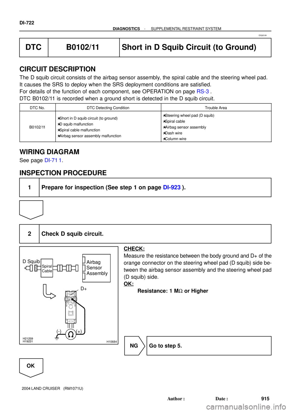
2 Check D squib circuit.
CHECK:
Measure the resistance between the body ground and D+ of the
orange connector on the steering wheel pad (D squib) side be-
tween the airbag sensor assembly and the steering wheel pad
(D squib) side.
OK:
Resistance: 1 MW or Higher
NG Go to step 5.
OK
DI3J0-04
Page 1508 of 3115
AB0119H19232
H21259
H21133
D Squib
Airbag
Sensor
Assembly
Spiral
Cable
D+
(-) (+)
ON
- DIAGNOSTICSSUPPLEMENTAL RESTRAINT SYSTEM
DI-727
920 Author�: Date�:
2004 LAND CRUISER (RM1071U)
DTC B0103/12 Short in D Squib Circuit (to B+)
CIRCUIT DESCRIPTION
The D squib circuit consists of the airbag sensor assembly, the spiral cable and the steering wheel pad.
It causes the SRS to deploy when the SRS deployment conditions are satisfied.
For details of the function of each components, see page OPERATION on page RS-3.
DTC B0103/12 is recorded when a B+ short is detected in the D squib circuit.
DTC No.DTC Detecting ConditionTrouble Area
B0103/12
�Short circuit in D squib circuit (to B+)
�D squib malfunction
�Spiral cable malfunction
�Airbag sensor assembly malfunction�Steering wheel pad (D squib)
�Spiral cable
�Airbag sensor assembly
�Dash wire
�Column wire
WIRING DIAGRAM
See page DI-71 1.
INSPECTION PROCEDURE
1 Prepare for inspection (See step 1 on page DI-923).
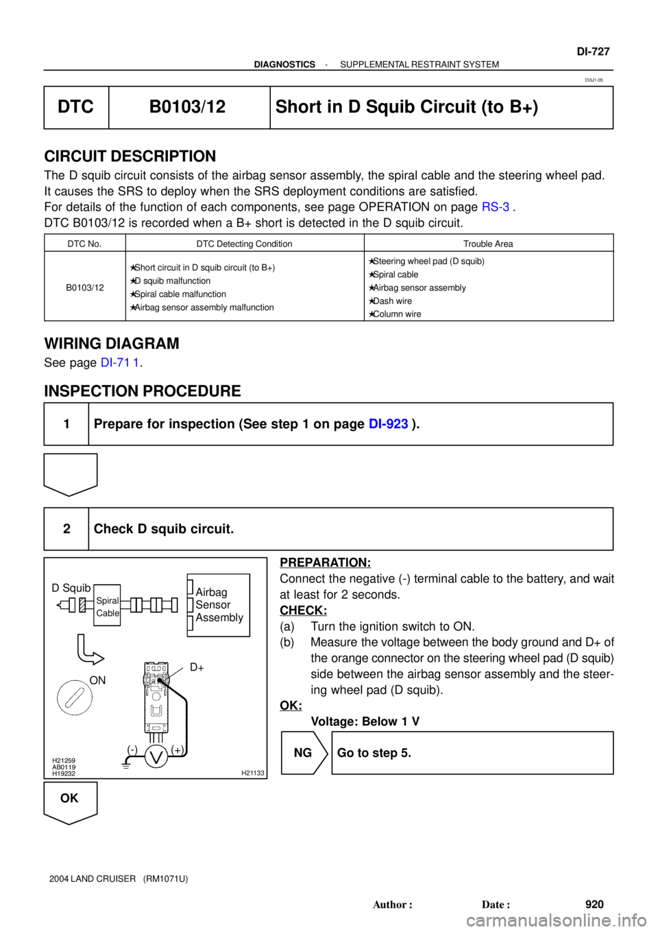
2 Check D squib circuit.
PREPARATION:
Connect the negative (-) terminal cable to the battery, and wait
at least for 2 seconds.
CHECK:
(a) Turn the ignition switch to ON.
(b) Measure the voltage between the body ground and D+ of
the orange connector on the steering wheel pad (D squib)
side between the airbag sensor assembly and the steer-
ing wheel pad (D squib).
OK:
Voltage: Below 1 V
NG Go to step 5.
OK
DI3J1-05
Page 1513 of 3115
H01454
A27
P Squib
10Airbag Sensor Assembly
2Y-R
C26
Y-G 1
11P+
P-
C26 DI-732
- DIAGNOSTICSSUPPLEMENTAL RESTRAINT SYSTEM
925 Author�: Date�:
2004 LAND CRUISER (RM1071U)
DTC B0105/53 Short in P Squib Circuit
CIRCUIT DESCRIPTION
The P squib circuit consists of the airbag sensor assembly and the front passenger airbag assembly.
It causes the SRS to deploy when the SRS deployment conditions are satisfied.
For details of the function of each component, see OPERATION on page RS-3.
DTC B0105/53 is recorded when a short is detected in the P squib circuit.
DTC No.DTC Detecting ConditionTrouble Area
B0105/53
�Short in P squib circuit
�P squib malfunction
�Airbag sensor assembly malfunction�Front passenger airbag assembly (P squib)
�Airbag sensor assembly
�Dash wire
WIRING DIAGRAM
DI6P7-26
Page 1517 of 3115
R14286H16854H17088
P Squib
Airbag
Sensor
Assembly
P+ P-
(-)(+)
Dash Wire
DI-736
- DIAGNOSTICSSUPPLEMENTAL RESTRAINT SYSTEM
929 Author�: Date�:
2004 LAND CRUISER (RM1071U)
DTC B0106/54 Open in P Squib Circuit
CIRCUIT DESCRIPTION
The P squib circuit consists of the airbag sensor assembly and the front passenger airbag assembly.
It causes the SRS to deploy when the SRS deployment conditions are satisfied.
For details of the function of each component, see OPERATION on page RS-3.
DTC B0106/54 is recorded when an open is detected in the P squib circuit.
DTC No.DTC Detecting ConditionTrouble Area
B0106/54
�Open in P squib circuit
�P squib malfunction
�Airbag sensor assembly malfunction�Front passenger airbag assembly (P squib)
�Airbag sensor assembly
�Dash wire
WIRING DIAGRAM
See page DI-732.
INSPECTION PROCEDURE
1 Prepare for inspection (See step 1 on page DI-923).
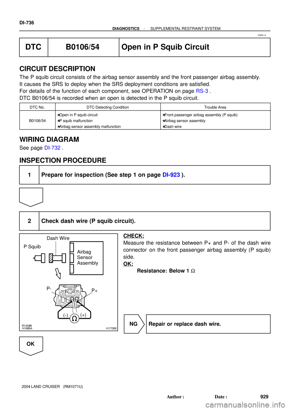
2 Check dash wire (P squib circuit).
CHECK:
Measure the resistance between P+ and P- of the dash wire
connector on the front passenger airbag assembly (P squib)
side.
OK:
Resistance: Below 1 W
NG Repair or replace dash wire.
OK
DI6P8-14
Page 1520 of 3115
H01227H16856H17090
P Squib
Airbag
Sensor
Assembly
(+) (-)P+
Dash Wire
- DIAGNOSTICSSUPPLEMENTAL RESTRAINT SYSTEM
DI-739
932 Author�: Date�:
2004 LAND CRUISER (RM1071U)
DTC B0107/51 Short in P Squib Circuit (to Ground)
CIRCUIT DESCRIPTION
The P squib circuit consists of the airbag sensor assembly and the front passenger airbag assembly.
It causes the SRS to deploy when the SRS deployment conditions are satisfied.
For details of the function of each component, see OPERATION on page RS-3.
DTC B0107/51 is recorded when ground short is detected in the P squib circuit.
DTC No.DTC Detecting ConditionTrouble Area
B0107/51
�Short in P squib circuit (to ground)
�P squib malfunction
�Airbag sensor assembly malfunction�Front passenger airbag assembly (P squib)
�Airbag sensor assembly
�Dash wire
WIRING DIAGRAM
See page DI-732.
INSPECTION PROCEDURE
1 Prepare for inspection (See step 1 on page DI-923).
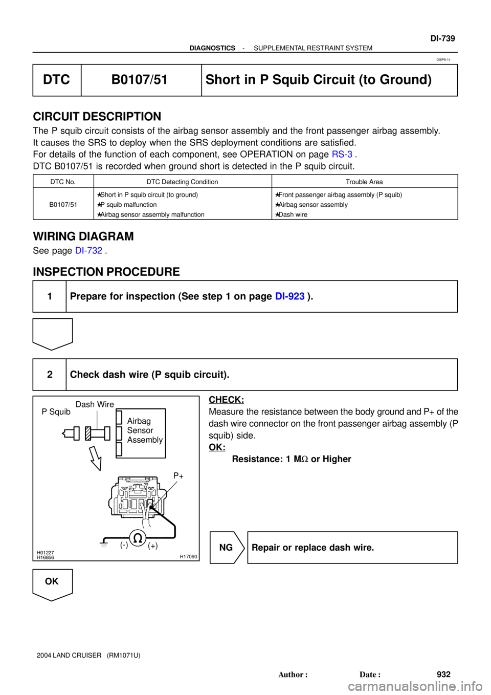
2 Check dash wire (P squib circuit).
CHECK:
Measure the resistance between the body ground and P+ of the
dash wire connector on the front passenger airbag assembly (P
squib) side.
OK:
Resistance: 1 MW or Higher
NG Repair or replace dash wire.
OK
DI6P9-14
Page 1523 of 3115
H01022AB0119H16857H17092
P SquibAirbag
Sensor
Assembly
(-)
(+)P+
ONDash Wire
DI-742
- DIAGNOSTICSSUPPLEMENTAL RESTRAINT SYSTEM
935 Author�: Date�:
2004 LAND CRUISER (RM1071U)
DTC B0108/52 Short in P Squib Circuit (to B+)
CIRCUIT DESCRIPTION
The P squib circuit consists of the airbag sensor assembly and the front passenger airbag assembly.
It causes the SRS to deploy when the SRS deployment conditions are satisfied.
For details of the function of each component, see OPERATION on page RS-3.
DTC B0108/52 is recorded when a B+ short is detected in the P squib circuit.
DTC No.DTC Detecting ConditionTrouble Area
B0108/52
�Short in P squib circuit (to B+)
�P squib malfunction
�Airbag sensor assembly malfunction�Front passenger airbag assembly (P squib)
�Airbag sensor assembly
�Dash wire
WIRING DIAGRAM
See page DI-732.
INSPECTION PROCEDURE
1 Prepare for inspection (See step 1 on page DI-923).
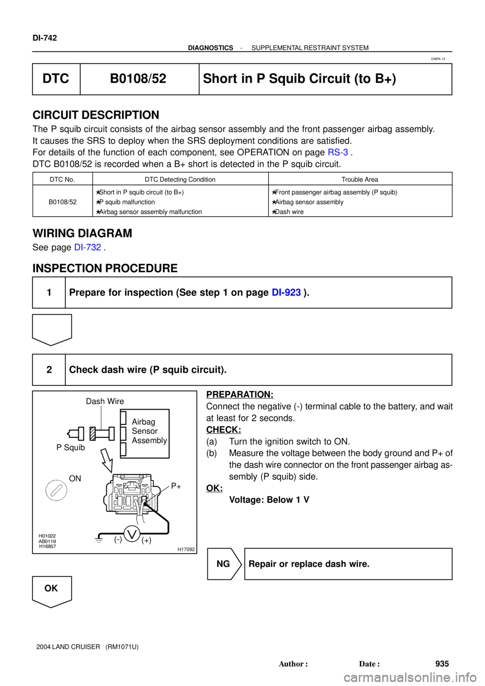
2 Check dash wire (P squib circuit).
PREPARATION:
Connect the negative (-) terminal cable to the battery, and wait
at least for 2 seconds.
CHECK:
(a) Turn the ignition switch to ON.
(b) Measure the voltage between the body ground and P+ of
the dash wire connector on the front passenger airbag as-
sembly (P squib) side.
OK:
Voltage: Below 1 V
NG Repair or replace dash wire.
OK
DI6PA-13
Page 1526 of 3115
H01454
S19
Side Squib RHAirbag Sensor Assembly
SFR+
SFR- Y-R
Y-G 1
26 5
C27
C27 (*1)
(*1)
*1: w/ Side Airbag
- DIAGNOSTICSSUPPLEMENTAL RESTRAINT SYSTEM
DI-745
938 Author�: Date�:
2004 LAND CRUISER (RM1071U)
DTC B0110/43 Short in Side Squib RH Circuit
CIRCUIT DESCRIPTION
The side squib RH circuit consists of the airbag sensor assembly and the side airbag assembly RH.
It causes the SRS to deploy when the SRS deployment conditions are satisfied.
For details of the function of each component, see OPERATION on page RS-3.
DTC B0110/43 is recorded when a short is detected in the side squib RH circuit.
DTC No.DTC Detecting ConditionTrouble Area
B0110/43
�Short in side squib RH circuit
�Side squib RH malfunction
�Airbag sensor assembly malfunction�Side airbag assembly RH (Side squib RH)
�Airbag sensor assembly
�Floor No. 2 wire
HINT:
DTC B0110/43 is indicated only for the vehicle equipped with the side airbag.
WIRING DIAGRAM
DI6PB-33
Page 1530 of 3115
H01019H16275H16616
Side Squib RHAirbag
Sensor
Assembly
(-) (+)
SFR+
SFR- Floor No. 2 Wire
- DIAGNOSTICSSUPPLEMENTAL RESTRAINT SYSTEM
DI-749
942 Author�: Date�:
2004 LAND CRUISER (RM1071U)
DTC B0111/44 Open in Side Squib RH Circuit
CIRCUIT DESCRIPTION
The side squib RH circuit consists of the airbag sensor assembly and the side airbag assembly RH.
It causes the SRS to deploy when the SRS deployment conditions are satisfied.
For details of the function of each component, see OPERATION on page RS-3.
DTC B0111/44 is recorded when an open is detected in the side squib RH circuit.
DTC No.DTC Detecting ConditionTrouble Area
B0111/44
�Open in side squib RH circuit
�Side squib RH malfunction
�Airbag sensor assembly malfunction�Side airbag assembly RH (Side squib RH)
�Airbag sensor assembly
�Floor No. 2 wire
HINT:
DTC B0111/44 is indicated only for the vehicle equipped with the side airbag.
WIRING DIAGRAM
See page DI-745.
INSPECTION PROCEDURE
1 Prepare for inspection (See step 1 on page DI-923).
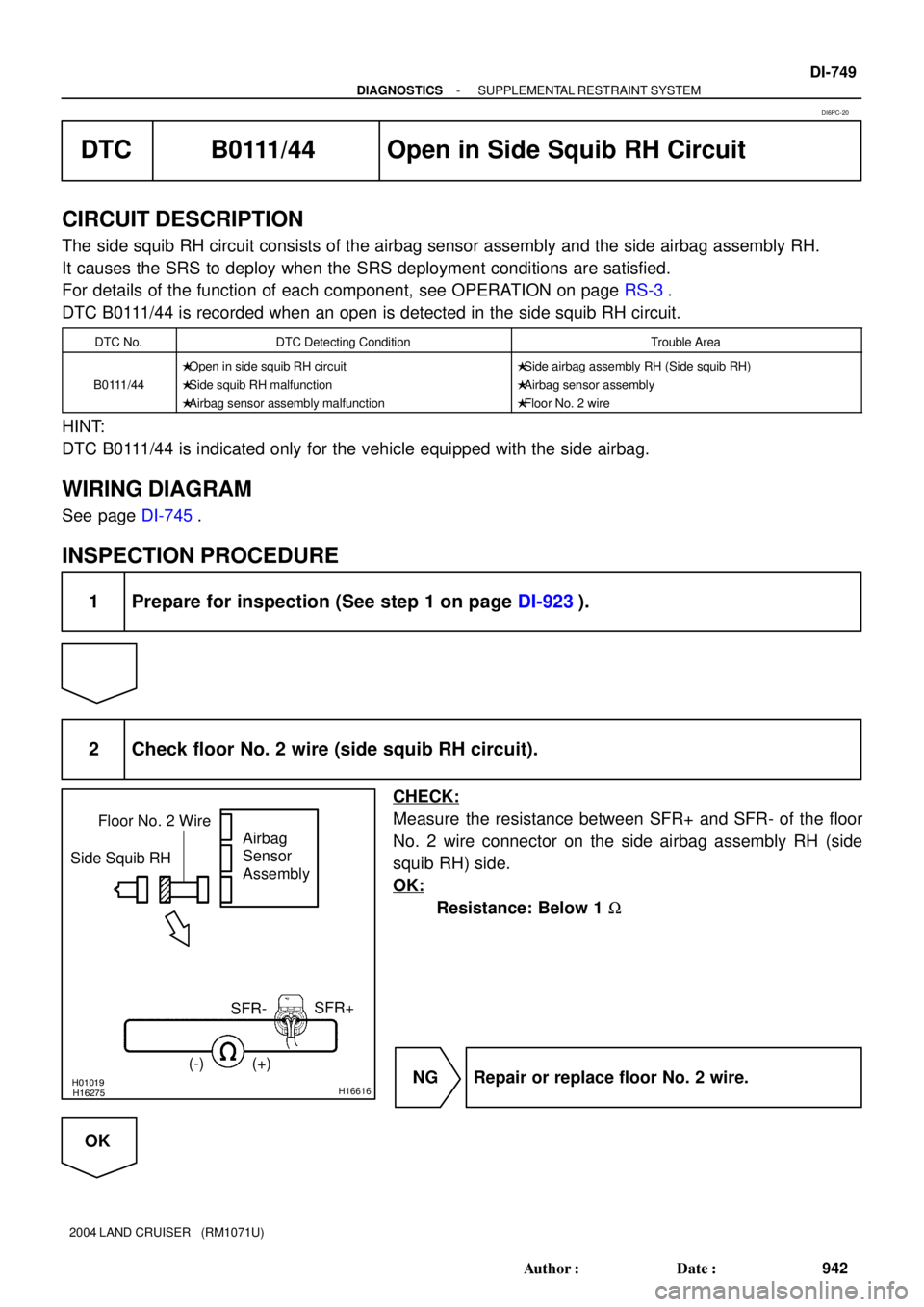
2 Check floor No. 2 wire (side squib RH circuit).
CHECK:
Measure the resistance between SFR+ and SFR- of the floor
No. 2 wire connector on the side airbag assembly RH (side
squib RH) side.
OK:
Resistance: Below 1 W
NG Repair or replace floor No. 2 wire.
OK
DI6PC-20