Page 3273 of 6000
8F–78BODY STRUCTURE
Tailgate Assembly (RH)
Parts Location
681RS004
Legend
(1) Tailgate Assembly (RH)
(2) Tailgate Trim Panel (RH)
(3) Tailgate Harness Connection(4) Rear Combination Light (RH)
(5) Tailgate Fixing Bolt
(6) Tailgate Hinge
Removal
1. Disconnect the battery ground cable.
2. Remove rear combination light (RH).
3. Remove tailgate trim panel (RH).
Refer to Exterior / Interrior Trim in this section.
4. Remove tailgate harness connection.
Disconnect the tailgate harness connection.
810RS004
Page 3278 of 6000
8F–83 BODY STRUCTURE
Tailgate Frame Cover (LH)
Parts Location
684RW001
Legend
(1) High Mount Stop Light(2) Washer Tube
(3) Tailgate Frame Cover
Removal
1. Disconnect the battery ground cable.
2. Remove tailgate frame cover.
Pull the tailgate frame cover (2) out.
Disconnect the washer tube (1) at the nozzle and
pull the washer tube out from the frame cover (2).
Disconnect the rear defogger and pull the harness
from the cover.
684RW002
Installation
1. Install the tailgate frame cover (1).
Hit the lower A edge portion of the cover to the
tailgate flange.
Clearance between the frame cover and the tailgate
panel (B portion) is 1 mm (0.04 in).
684RS008
Page 3285 of 6000
8F–90BODY STRUCTURE
Headlining
Parts Location
666RW003
Legend
(1) Clip
(2) Interior Trim Panels
(3) Sun Roof Finisher (W/Sun Roof)
(4) Headlining
(5) Dome Light(6) Sunvisors
(7) Map Light
(8) Sunvisor Holder
(9) Rear View Mirror
(10) Multi Meter
Removal
1. Disconnect the battery ground cable.
2. Remove interior trim panels.
Refer to Exterior / Interrior Trim in this section.
3. Remove dome light.
Remove the dome light lens and the fixing screws.
Disconnect the dome light connectors.
4. Remove multi meter (4) (If so eguipped).
Remove two caps (2), two screws (3) and
disconnect the connector (1).
821RW241
Page 3286 of 6000
8F–91 BODY STRUCTURE
5. Remove rear view mirror.
Remove the rubber stopper (1).
Pry off the mirror stay cover (2) and remove 3
screws.
720RW004
6. Remove map light/sun roof switch.
Pry the map light clip free from the map light/sun
roof switch bracket and disconnect the connector.
805RS001
7. Remove sunvisors.
Remove the fixing screw and turn the sunvisor
holder (1) to remove it.
Disconnect the vanity mirror illumination connector.
743RW008
8. Remove sun roof finisher (W/Sun roof).
9. Remove headlining.
Remove the headlining fixing clips.
Installation
To install, follow the removal steps in the reverse order,
noting the following points.
1. Install the headlining so that the fixing clips will not
come off.
2. To install the sun roof finisher (3), first fit in at one
place with the head lining (2) close to the sun roof
frame complete (1), then install the entire finisher
tightly by hitting it with a plastic hammer, not allowing
it to move up.
665RS001
Page 3326 of 6000
8G–14SEATS
Seat Heater System
General Description
The circuit consists of the starter switch, seat heater
switch and the heat unit.
The seat heater is provided in driver’s and front
passenger seats (as option).
When the seat heater switch is ON, the seat heat built in
the seat back and cushion is switched on to warm the
seats.
To prevent the seats from being overheated, the circuit is
fitted with a thermostat.
Seat Heater Switch Removal and
Installation
Refer to the Seat Heater Switch removal and installation
steps in Lighting System section.
Heat Unit Parts Location
750RS018
Legend
(1) Heat Unit (Seat Back Side)
750RS019
Legend
(2) Heat Unit (Seat Cushion Side)
Heat Unit Removal and Installation
Refer to the Power Seat Assembly disassembly and
reassembly steps in this section.
Page 3361 of 6000

8H–22SECURITY AND LOCKS
Anti-theft System
General Description
The circuit consists of the starter switch, anti-theft &
keyless entry control unit, anti-theft horn, front door and
tailgate key switch (detect and tamper switch), door lock
(& power window) switch, door lock actuator for each
door, engine hood switch, clutch start switch (M/T),
ANTI-THEFT indicator light and mode switch (A/T).
The system operates as follows: After locking the starter
switch and removing the starter key (this sets the alarm),
if the door is unlocked in any way other than with the
proper key, the headlights start flashing, the horn sounds,
and the starter circuit is disabled. (However, the engine
hood and all the doors must be locked and closed.)
Once the system has been placed in the warning or alarm
condition, it can be released only when the starter switch
is shifted from “OFF” to “ACC” by the starter key, or when
the lock of the front door or the tailgate is released (to
activate the detect switch) by the starter key.
Anti-theft & Keyless Entry Control
Unit Removal
1. Disconnect the battery ground cable.
2. Remove the front console assembly.
Refer to the Instrument Panel Assembly in Body
Structure section.
3. Remove the lower cluster assembly.
Refer to the Instrument Panel Assembly in Body
Structure section.
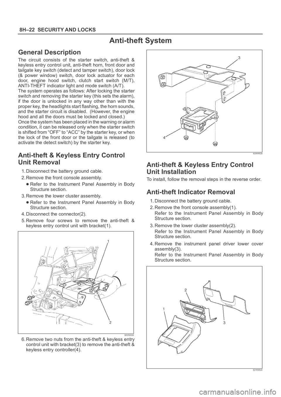
4. Disconnect the connector(2).
5. Remove four screws to remove the anti-theft &
keyless entry control unit with bracket(1).
825RW029
6. Remove two nuts from the anti-theft & keyless entry
control unit with bracket(3) to remove the anti-theft &
keyless entry controller(4).
825RW028
Anti-theft & Keyless Entry Control
Unit Installation
To install, follow the removal steps in the reverse order.
Anti-theft Indicator Removal
1. Disconnect the battery ground cable.
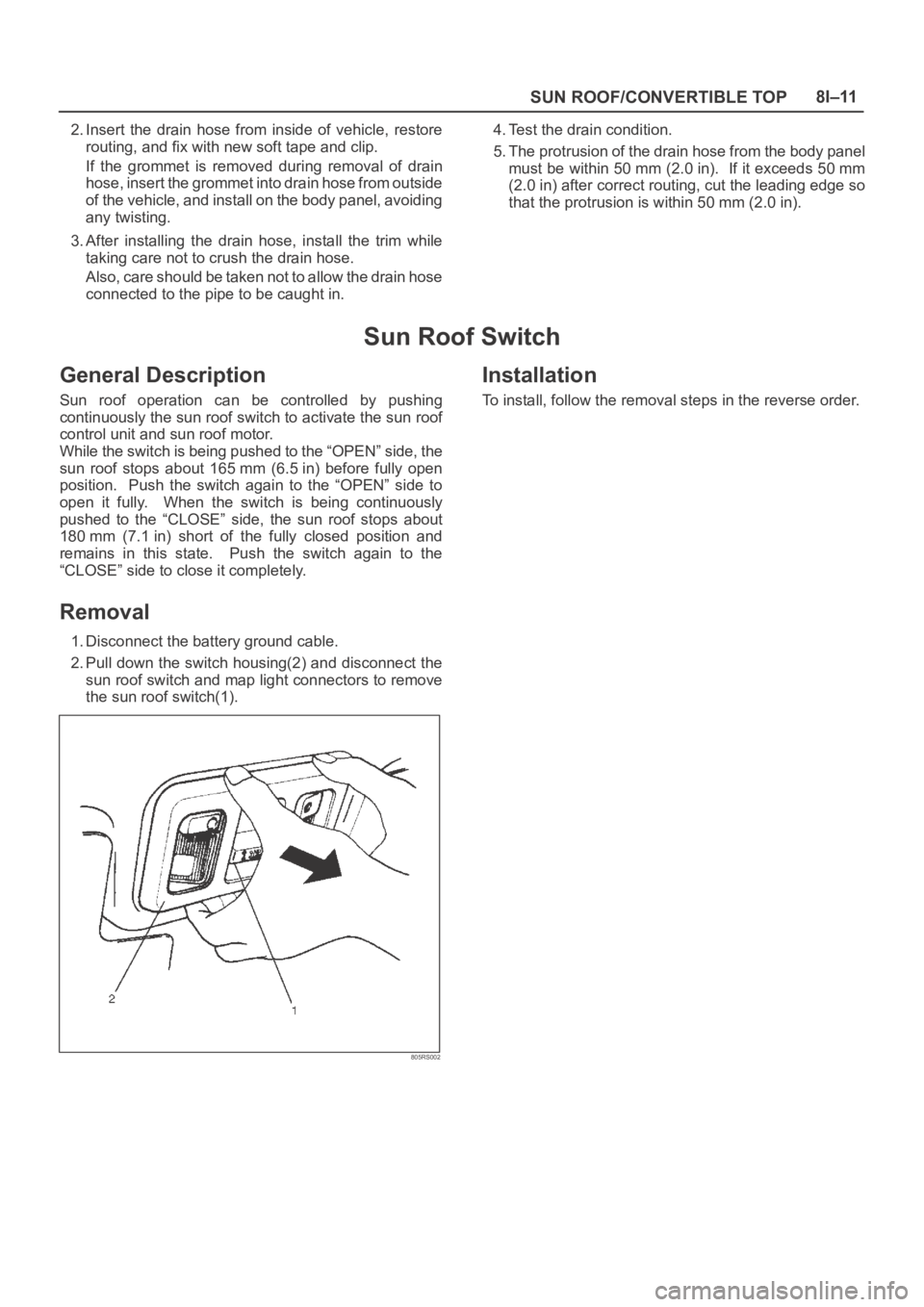
2. Remove the front console assembly(1).
Refer to the Instrument Panel Assembly in Body
Structure section.
3. Remove the lower cluster assembly(2).
Refer to the Instrument Panel Assembly in Body
Structure section.
4. Remove the instrument panel driver lower cover
assembly(3).
Refer to the Instrument Panel Assembly in Body
Structure section.
821RW024
Page 3378 of 6000

SUN ROOF/CONVERTIBLE TOP8I–11
2. Insert the drain hose from inside of vehicle, restore
routing, and fix with new soft tape and clip.
If the grommet is removed during removal of drain
hose, insert the grommet into drain hose from outside
of the vehicle, and install on the body panel, avoiding
any twisting.
3. After installing the drain hose, install the trim while
taking care not to crush the drain hose.
Also, care should be taken not to allow the drain hose
connected to the pipe to be caught in.4. Test the drain condition.
5. The protrusion of the drain hose from the body panel
must be within 50 mm (2.0 in). If it exceeds 50 mm
(2.0 in) after correct routing, cut the leading edge so
that the protrusion is within 50 mm (2.0 in).
Sun Roof Switch
General Description
Sun roof operation can be controlled by pushing
continuously the sun roof switch to activate the sun roof
control unit and sun roof motor.
While the switch is being pushed to the “OPEN” side, the
sun roof stops about 165 mm (6.5 in) before fully open
position. Push the switch again to the “OPEN” side to
open it fully. When the switch is being continuously
pushed to the “CLOSE” side, the sun roof stops about
180 mm (7.1 in) short of the fully closed position and
remains in this state. Push the switch again to the
“CLOSE” side to close it completely.
Removal
1. Disconnect the battery ground cable.
2. Pull down the switch housing(2) and disconnect the
sun roof switch and map light connectors to remove
the sun roof switch(1).
805RS002
Installation
To install, follow the removal steps in the reverse order.
Page 3385 of 6000
8J–6EXTERIOR/INTERIOR TRIM
Front Door Trim Panel
Front Door Trim Panel and Associated Parts
635RW011
Legend
(1) Power Window Switch
(2) Door Mirror Cover
(3) Door Trim Panel
(4) Courtesy Light
(5) Front Speaker
(6) Speaker Cover(7) Regulator Handle
(8) Inside Handle Fixing Screw
(9) Inside Handle
(10) Hook
(11) Washer
(12) Inside Pull Handle
(13) Inside Pull Handle (W/O Power Window)
Removal
1. Disconnect the battery ground cable.