Page 4120 of 6000
4B2–37 DRIVE LINE CONTROL SYSTEM (TOD)
No.NAMECONTENTS
1VIGPower supply (IG)
2N.CNot used
34WD OUT4WD signal output
4SOL (+)Electromagnetic solenoid
5ADC (+)Axle disconnect output
6LIGHTING SWLighting SW input
7BRAKEBrake SW input
84H SW4H SW input
94L SW4L SW input
10AXEL SWAXEL SW input
11ABS INOperation signal input
12TOD SWTOD SW input
13DIAGSelf-diagnosis input
14D-G MAPD-G MAP recognition input (Only V6 engine)
15Ref.Vehicle speed sensor supply
16N.CNot used
17N.CNot used
18COM (–)Vehicle speed sensor GND
19S-GNDSensor GND
20P-GNDPower GND
21TPSThrottle position sensor
22TECH 2TECH 2 output
23Rer. SigRear vehicle speed sensor input
24Frt. SigFront vehicle speed sensor input
25IND.a4WD display signal a
26IND.b4WD display signal b
27IND.c4WD display signal c
28IND.AUTOAUTO display output
29IND RrRear display output
30CHECKTOD warning lamp
Page 4122 of 6000

4B2–39 DRIVE LINE CONTROL SYSTEM (TOD)
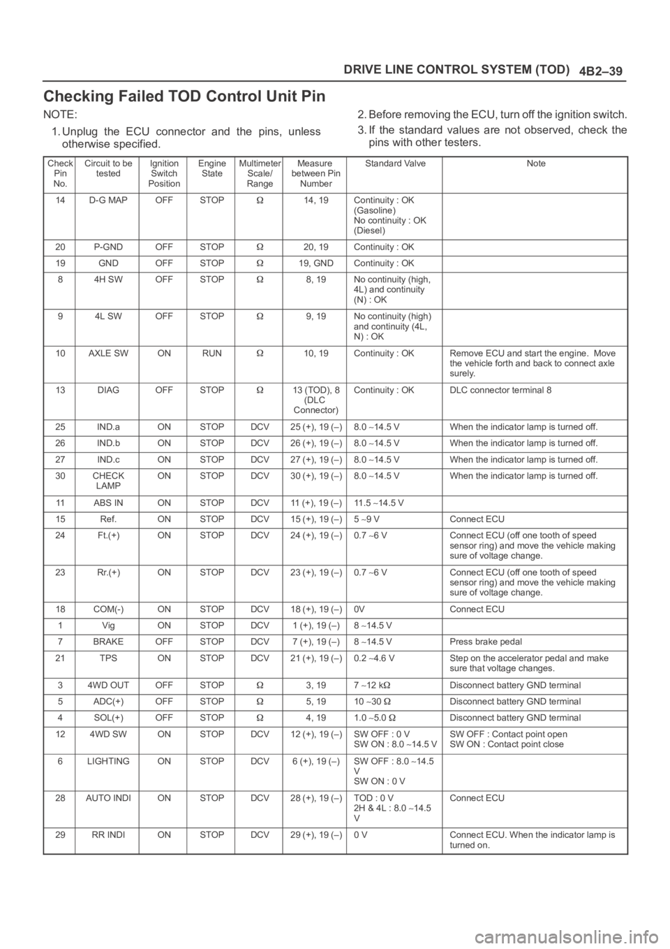
Checking Failed TOD Control Unit Pin
NOTE:
1. Unplug the ECU connector and the pins, unless
otherwise specified.2. Before removing the ECU, turn off the ignition switch.
3. If the standard values are not observed, check the
pins with other testers.
Check
Pin
No.Circuit to be
testedIgnition
Switch
PositionEngine
StateMultimeter
Scale/
RangeMeasure
between Pin
NumberStandard ValveNote
14D-G MAPOFFSTOP14, 19Continuity : OK
(Gasoline)
No continuity : OK
(Diesel)
20P-GNDOFFSTOP20, 19Continuity : OK
19GNDOFFSTOP19, GNDContinuity : OK
84H SWOFFSTOP8, 19No continuity (high,
4L) and continuity
(N) : OK
94L SWOFFSTOP9, 19No continuity (high)
and continuity (4L,
N) : OK
10AXLE SWONRUN10, 19Continuity : OKRemove ECU and start the engine. Move
the vehicle forth and back to connect axle
surely.
13DIAGOFFSTOP13 (TOD), 8
(DLC
Connector)Continuity : OKDLC connector terminal 8
25IND.aONSTOPDCV25 (+), 19 (–)8.0 14.5 VWhen the indicator lamp is turned off.
26IND.bONSTOPDCV26 (+), 19 (–)8.0 14.5 VWhen the indicator lamp is turned off.
27IND.cONSTOPDCV27 (+), 19 (–)8.0 14.5 VWhen the indicator lamp is turned off.
30CHECK
LAMPONSTOPDCV30 (+), 19 (–)8.0 14.5 VWhen the indicator lamp is turned off.
11ABS INONSTOPDCV11 (+), 19 (–)11 . 5 14.5 V
15Ref.ONSTOPDCV15 (+), 19 (–)5 9 VConnect ECU
24Ft.(+)ONSTOPDCV24 (+), 19 (–)0.7 6 VConnect ECU (off one tooth of speed
sensor ring) and move the vehicle making
sure of voltage change.
23Rr.(+)ONSTOPDCV23 (+), 19 (–)0.7 6 VConnect ECU (off one tooth of speed
sensor ring) and move the vehicle making
sure of voltage change.
18COM(-)ONSTOPDCV18 (+), 19 (–)0VConnect ECU
1VigONSTOPDCV1 (+), 19 (–)8 14.5 V
7BRAKEOFFSTOPDCV7 (+), 19 (–)8 14.5 VPress brake pedal
21TPSONSTOPDCV21 (+), 19 (–)0.2 4.6 VStep on the accelerator pedal and make
sure that voltage changes.
34WD OUTOFFSTOP3, 197 12 kDisconnect battery GND terminal
5ADC(+)OFFSTOP5, 1910 30 Disconnect battery GND terminal
4SOL(+)OFFSTOP4, 191.0 5.0 Disconnect battery GND terminal
124WD SWONSTOPDCV12 (+), 19 (–)SW OFF : 0 V
SW ON : 8.0 14.5 VSW OFF : Contact point open
SW ON : Contact point close
6LIGHTINGONSTOPDCV6 (+), 19 (–)SW OFF : 8.0 14.5
V
SW ON : 0 V
28AUTO INDIONSTOPDCV28 (+), 19 (–)TOD : 0 V
2H & 4L : 8.0 14.5
VConnect ECU
29RR INDIONSTOPDCV29 (+), 19 (–)0 VConnect ECU. When the indicator lamp is
turned on.
Page 4157 of 6000
DRIVE LINE CONTROL SYSTEM (TOD) 4B2–74
Trouble Diagnosis Depending on The
Status of TOD Indicator
Functional check with TOD indicator light is conducted
prior to check on Charts A–H.
After the starter is switched on, check and see if the
status has become as tabulated below.
C07RW012–1
If the status is as tabulated above, there is no
problem. If not as tabulated above, inspect the
harness.
Page 4195 of 6000
DRIVE LINE CONTROL SYSTEM (TOD) 4B2–112
Chart Hlighting switch circuit
Function of circuitReads in the status of lighting switch and reduces the indicator brightness at night.
Fail conditionEven if the lighting switch is pressed on and off, brightness does not change.
Indicator lamp status
Transfer positionAll position (example TOD mode)
D04RY00073
Page 4196 of 6000
4B2–113 DRIVE LINE CONTROL SYSTEM (TOD)
StepActionYe sNo
11. Disconnect ECU connector.
2. Turn on the starter switch.
Is battery voltage observed between ECU terminals (B–68)1 and
(B–67)11?
Go to Step 2
Wirers are broken
lighting SW
circuit. Repair
the circuit.
Go to Step 4
2Turn lighting SW “ON”.
Is 0 V observed between ECU terminal (B–68)1 and (B–67)11?
Go to Step 3
Lighting SW
circuit battery
short. Repair the
circuit.
Go to Step 4
3Connect ECU terminal.
While the lighting switch is pressed on and off, does the
brightness of the indicator change?The phenomenon
is not
reproduced.
Refer to
“Troubles
intermittently
observed”
The ECU has
failed. Replace
the ECU.
Go to Step 4
4Check that all the parts are mounted.
Is this step complete?Repeat the
“Diagnosis Flow”.
Return to Step 4
Page 4211 of 6000
4C–5 DRIVE SHAFT SYSTEM
7.Remove the parking brake cable mounting
bolts(Behind the back plate)(1).
311RS001
8. Remove the bearing holder mounting nuts.
9. Remove axle shaft assembly.
NOTE: Be sure not to damage the oil seal.
10. Remove snap ring.
11. Using a bearing remover 5–8840–2295–0 and press,
remove retainer together with the bearing holder.
420RW024
12. Remove bearing.
13. Remove bearing holder.
14. Remove back plate.15. Remove the wheel pins using a remover
5–8840–0079–0.
420RW023
Inspection and Repair
Make necessary correction or parts replacement if wear,
corrosion or any other abnormal conditions are found
through inspection.
Visual Check:
Check the following parts for wear, damage, noise or any
other abnormal conditions:
1. Axle shaft
2. Bearing
When checking the axle shaft, pay special attention to the
splined portions and replace the shaft if distortion or step
wear is noticeable. Correct slight step wear with a grinder.
420RS008
Page 4268 of 6000
TRANSFER CASE (STANDARD TYPE)
4D1–7
A/T, WO/Shift On The Fly, WO/4WD Switch, model
A07RW055
The transfer case is used to provide a means of providing
power flow to the front axle. The transfer case also
provides a means of disconnecting the front axle,
providing better fuel economy and quieter operation when
the vehicle is driven on improved roads where four wheel
drive is not required. In addition, the transfer case
provides an additional gear reduction when placed in low
range, which is useful when difficult off–road conditions
are encountered.
A floor mounted shift lever is used to select the high–low
range. When four wheel drive switch has been turned on,
the four wheel drive indicator light is designed to come on
when the front axle has been engaged.
Page 4295 of 6000

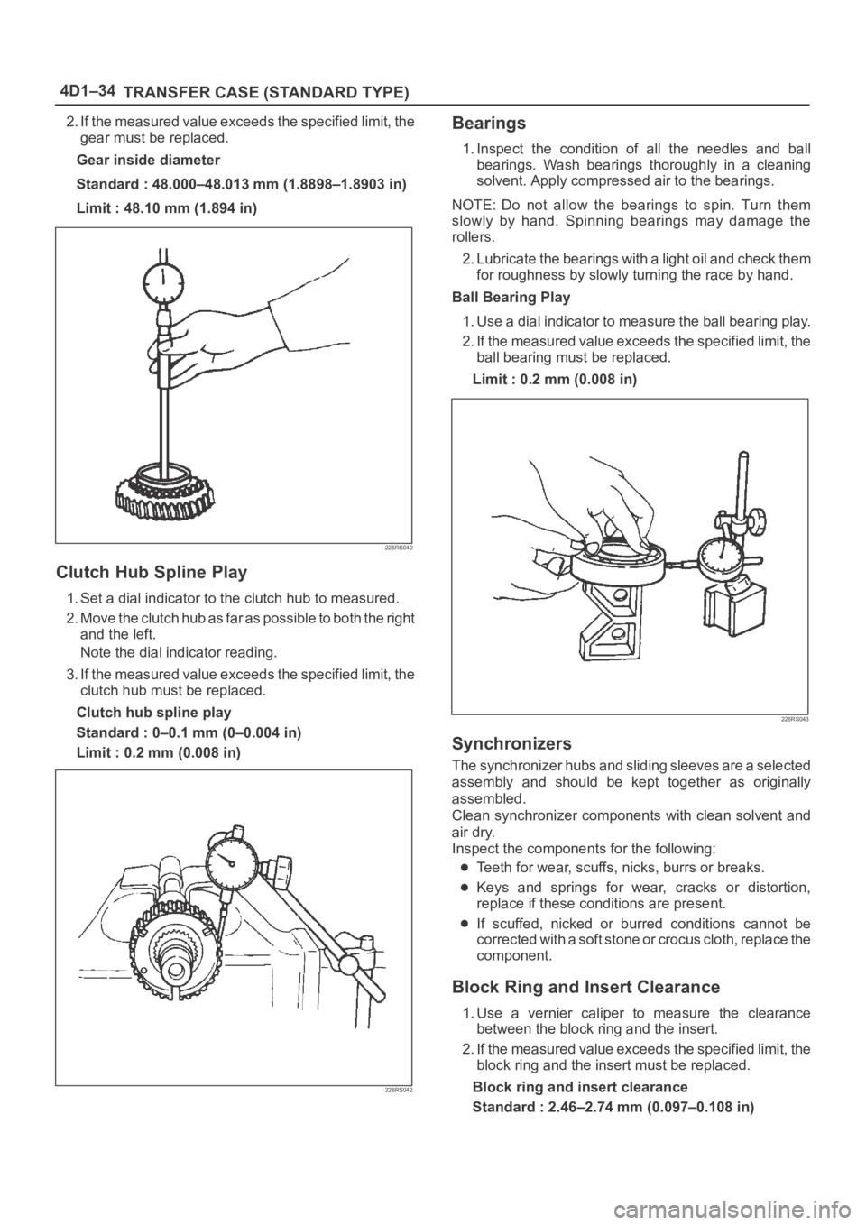
4D1–34
TRANSFER CASE (STANDARD TYPE)
2. If the measured value exceeds the specified limit, the
gear must be replaced.
Gear inside diameter
Standard : 48.000–48.013 mm (1.8898–1.8903 in)
Limit : 48.10 mm (1.894 in)
226RS040
Clutch Hub Spline Play
1. Set a dial indicator to the clutch hub to measured.
2. Move the clutch hub as far as possible to both the right
and the left.
Note the dial indicator reading.
3. If the measured value exceeds the specified limit, the
clutch hub must be replaced.
Clutch hub spline play
Standard : 0–0.1 mm (0–0.004 in)
Limit : 0.2 mm (0.008 in)
226RS042
Bearings
1. Inspect the condition of all the needles and ball
bearings. Wash bearings thoroughly in a cleaning
solvent. Apply compressed air to the bearings.
NOTE: Do not allow the bearings to spin. Turn them
slowly by hand. Spinning bearings may damage the
rollers.
2. Lubricate the bearings with a light oil and check them
for roughness by slowly turning the race by hand.
Ball Bearing Play
1. Use a dial indicator to measure the ball bearing play.
2. If the measured value exceeds the specified limit, the
ball bearing must be replaced.
Limit : 0.2 mm (0.008 in)
226RS043
Synchronizers
The synchronizer hubs and sliding sleeves are a selected
assembly and should be kept together as originally
assembled.
Clean synchronizer components with clean solvent and
air dry.
Inspect the components for the following:
Teeth for wear, scuffs, nicks, burrs or breaks.
Keys and springs for wear, cracks or distortion,
replace if these conditions are present.
If scuffed, nicked or burred conditions cannot be
corrected with a soft stone or crocus cloth, replace the
component.
Block Ring and Insert Clearance
1. Use a vernier caliper to measure the clearance
between the block ring and the insert.
2. If the measured value exceeds the specified limit, the
block ring and the insert must be replaced.
Block ring and insert clearance
Standard : 2.46–2.74 mm (0.097–0.108 in)