1998 OPEL FRONTERA light
[x] Cancel search: lightPage 4405 of 6000
5A–55 BRAKE CONTROL SYSTEM
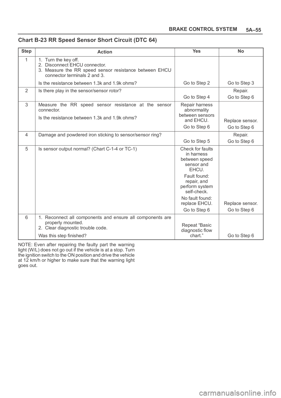
Chart B-23 RR Speed Sensor Short Circuit (DTC 64)
StepActionYe sNo
11. Turn the key off.
2. Disconnect EHCU connector.
3. Measure the RR speed sensor resistance between EHCU
connector terminals 2 and 3.
Is the resistance between 1.3k and 1.9k ohms?
Go to Step 2Go to Step 3
2Is there play in the sensor/sensor rotor?
Go to Step 4
Repair.
Go to Step 6
3Measure the RR speed sensor resistance at the sensor
connector.
Is the resistance between 1.3k and 1.9k ohms?Repair harness
abnormality
between sensors
and EHCU.
Go to Step 6
Replace sensor.
Go to Step 6
4Damage and powdered iron sticking to sensor/sensor ring?
Go to Step 5
Repair.
Go to Step 6
5Is sensor output normal? (Chart C-1-4 or TC-1)Check for faults
in harness
between speed
sensor and
EHCU.
Fault found:
repair, and
perform system
self-check.
No fault found:
replace EHCU.
Go to Step 6
Replace sensor.
Go to Step 6
61. Reconnect all components and ensure all components are
properly mounted.
2. Clear diagnostic trouble code.
Was this step finished?
Repeat “Basic
diagnostic flow
chart.”
Go to Step 6
NOTE: Even after repairing the faulty part the warning
light (W/L) does not go out if the vehicle is at a stop. Turn
the ignition switch to the ON position and drive the vehicle
at 12 km/h or higher to make sure that the warning light
goes out.
Page 4406 of 6000
5A–56
BRAKE CONTROL SYSTEM
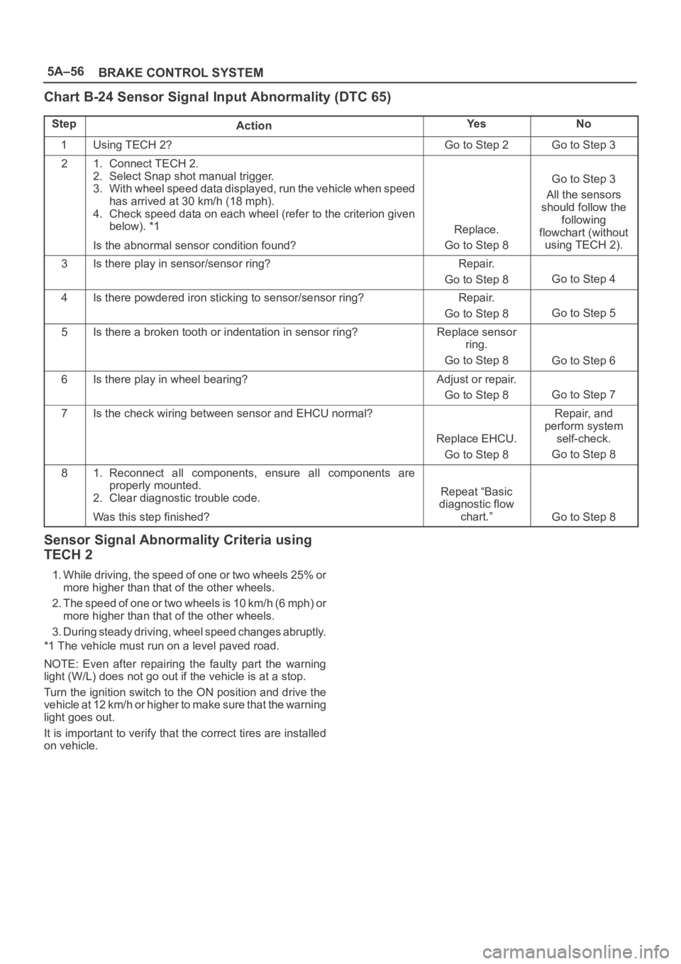
Chart B-24 Sensor Signal Input Abnormality (DTC 65)
StepActionYe sNo
1Using TECH 2?Go to Step 2Go to Step 3
21. Connect TECH 2.
2. Select Snap shot manual trigger.
3. With wheel speed data displayed, run the vehicle when speed
has arrived at 30 km/h (18 mph).
4. Check speed data on each wheel (refer to the criterion given
below). *1
Is the abnormal sensor condition found?
Replace.
Go to Step 8
Go to Step 3
All the sensors
should follow the
following
flowchart (without
using TECH 2).
3Is there play in sensor/sensor ring?Repair.
Go to Step 8
Go to Step 4
4Is there powdered iron sticking to sensor/sensor ring?Repair.
Go to Step 8
Go to Step 5
5Is there a broken tooth or indentation in sensor ring?Replace sensor
ring.
Go to Step 8
Go to Step 6
6Is there play in wheel bearing?Adjust or repair.
Go to Step 8
Go to Step 7
7Is the check wiring between sensor and EHCU normal?
Replace EHCU.
Go to Step 8
Repair, and
perform system
self-check.
Go to Step 8
81. Reconnect all components, ensure all components are
properly mounted.
2. Clear diagnostic trouble code.
Was this step finished?
Repeat “Basic
diagnostic flow
chart.”
Go to Step 8
Sensor Signal Abnormality Criteria using
TECH 2
1. While driving, the speed of one or two wheels 25% or
more higher than that of the other wheels.
2. The speed of one or two wheels is 10 km/h (6 mph) or
more higher than that of the other wheels.
3. During steady driving, wheel speed changes abruptly.
*1 The vehicle must run on a level paved road.
NOTE: Even after repairing the faulty part the warning
light (W/L) does not go out if the vehicle is at a stop.
Turn the ignition switch to the ON position and drive the
vehicle at 12 km/h or higher to make sure that the warning
light goes out.
It is important to verify that the correct tires are installed
on vehicle.
Page 4407 of 6000
5A–57 BRAKE CONTROL SYSTEM
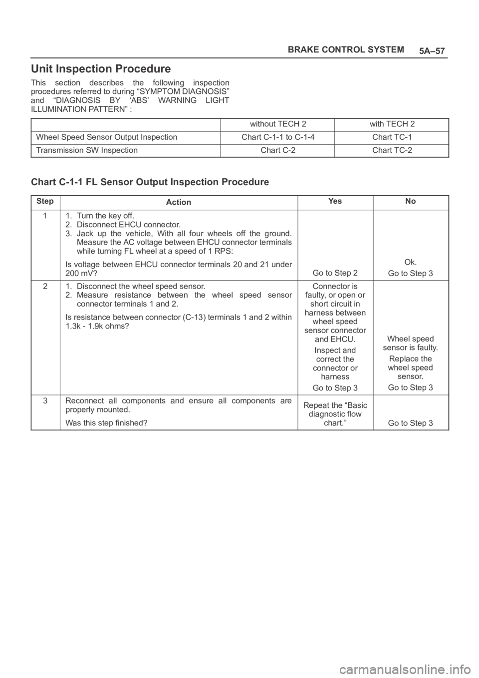
Unit Inspection Procedure
This section describes the following inspection
procedures referred to during “SYMPTOM DIAGNOSIS”
and “DIAGNOSIS BY ‘ABS’ WARNING LIGHT
ILLUMINATION PATTERN” :
without TECH 2with TECH 2
Wheel Speed Sensor Output InspectionChart C-1-1 to C-1-4Chart TC-1
Transmission SW InspectionChart C-2Chart TC-2
Chart C-1-1 FL Sensor Output Inspection Procedure
StepActionYe sNo
11. Turn the key off.
2. Disconnect EHCU connector.
3. Jack up the vehicle, With all four wheels off the ground.
Measure the AC voltage between EHCU connector terminals
while turning FL wheel at a speed of 1 RPS:
Is voltage between EHCU connector terminals 20 and 21 under
200 mV?
Go to Step 2
Ok.
Go to Step 3
21. Disconnect the wheel speed sensor.
2. Measure resistance between the wheel speed sensor
connector terminals 1 and 2.
Is resistance between connector (C-13) terminals 1 and 2 within
1.3k - 1.9k ohms?Connector is
faulty, or open or
short circuit in
harness between
wheel speed
sensor connector
and EHCU.
Inspect and
correct the
connector or
harness
Go to Step 3
Wheel speed
sensor is faulty.
Replace the
wheel speed
sensor.
Go to Step 3
3Reconnect all components and ensure all components are
properly mounted.
Was this step finished?Repeat the “Basic
diagnostic flow
chart.”
Go to Step 3
Page 4500 of 6000
6A–4
ENGINE MECHANICAL
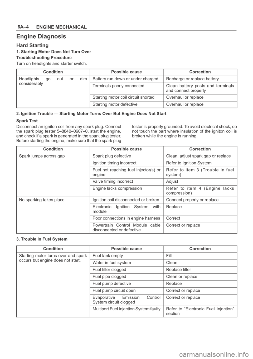
Engine Diagnosis
Hard Starting
1. Starting Motor Does Not Turn Over
Troubleshooting Procedure
Turn on headlights and starter switch.
Condition
Possible causeCorrection
Headlights go out or dim
considerably
Battery run down or under chargedRecharge or replace battery
considerablyTerminals poorly connectedClean battery posts and terminals
and connect properly
Starting motor coil circuit shortedOverhaul or replace
Starting motor defectiveOverhaul or replace
2. Ignition Trouble — Starting Motor Turns Over But Engine Does Not Start
Spark Test
Disconnect an igniton coil from any spark plug. Connect
the spark plug tester 5–8840–0607–0, start the engine,
a n d c h e c k i f a s p a r k i s g e n e r a t e d in t h e s p a r k p l u g t e s t e r.
Before starting the engine, make sure that the spark plugtester is properly grounded. To avoid electrical shock, do
not touch the part where insulation of the igniton coil is
broken while the engine is running.
Condition
Possible causeCorrection
Spark jumps across gapSpark plug defectiveClean, adjust spark gap or replace
Ignition timing incorrectRefer to Ignition System
Fuel not reaching fuel injector(s) or
engineRefer to item 3 (Trouble in fuel
system)
Valve timing incorrectAdjust
Engine lacks compressionRefer to item 4 (Engine lacks
compression)
No sparking takes placeIgnition coil disconnected or brokenConnect properly or replace
Electronic Ignition System with
moduleReplace
Poor connections in engine harnessCorrect
Powertrain Control Module cable
disconnected or defectiveCorrect or replace
3. Trouble In Fuel System
Condition
Possible causeCorrection
Starting motor turns over and spark
occurs but engine does not start
Fuel tank emptyFill
occurs but engine does not start.Water in fuel systemClean
Fuel filter cloggedReplace filter
Fuel pipe cloggedClean or replace
Fuel pump defectiveReplace
Fuel pump circuit openCorrect or replace
Evaporative Emission Control
System circuit cloggedCorrect or replace
Multiport Fuel Injection System faultyRefer to “Electronic Fuel Injection”
section
Page 4508 of 6000
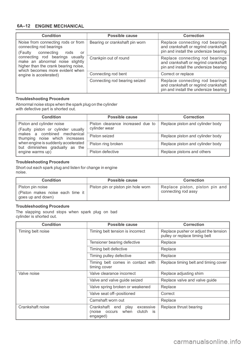
6A–12
ENGINE MECHANICAL
ConditionPossible causeCorrection
Noise from connecting rods or from
connecting rod bearings
(Faulty connecting rods orBearing or crankshaft pin wornReplace connecting rod bearings
and crankshaft or regrind crankshaft
pin and install the undersize bearing
yg
connecting rod bearings usually
make an abnormal noise slightly
higher than the crank bearing noise,
which becomes more evident when
Crankpin out of roundReplace connecting rod bearings
and crankshaft or regrind crankshaft
pin and install the undersize bearing
which becomes more evident when
engine is accelerated)Connecting rod bentCorrect or replaceg)
Connecting rod bearing seizedReplace connecting rod bearings
and crankshaft or regrind crankshaft
pin and install the undersize bearing
Troubleshooting Procedure
Abnormal noise stops when the spark plug on the cylinder
with defective part is shorted out.
Condition
Possible causeCorrection
Piston and cylinder noise
(Faulty piston or cylinder usually
kbidhil
Piston clearance increased due to
cylinder wearReplace piston and cylinder body
makes a combined mechanical
thumping noise which increasesPiston seizedReplace piston and cylinder bodyg
when engine is suddenly accelerated
but diminishes
gradually as thePiston ring brokenReplace piston and cylinder bodybut diminishes gradually as the
engine warms up)Piston defectiveReplace pistons and others
Troubleshooting Procedure
Short out each spark plug and listen for change in engine
noise.
Condition
Possible causeCorrection
Piston pin noise
(Piston makes noise each time it
goes up and down)Piston pin or piston pin hole wornReplace piston, piston pin and
connecting rod assy
Troubleshooting Procedure
The slapping sound stops when spark plug on bad
cylinder is shorted out.
Condition
Possible causeCorrection
Timing belt noiseTiming belt tension is incorrectReplace pusher or adjust the tension
pulley or replace timing belt
Tensioner bearing defectiveReplace
Timing belt defectiveReplace
Timing pulley defectiveReplace
Timing belt comes in contact with
timing coverReplace timing belt and timing cover
Valve noiseValve clearance incorrectReplace adjusting shim
Valve and valve guide seizedReplace valve and valve guide
Valve spring broken or weakenedReplace
Valve seat off–positionedCorrect
Camshaft worn outReplace
Crankshaft noiseCrankshaft end play excessive
(noise occurs when clutch is
engaged)Replace thrust bearing
Page 4525 of 6000
6A–29
ENGINE MECHANICAL
Timing Belt
Removal
1. Disconnect battery ground cable.
2. Remove air cleaner assembly.
3. Remove radiator upper fan shroud from radiator.
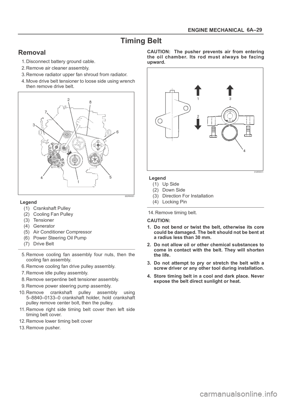
4. Move drive belt tensioner to loose side using wrench
then remove drive belt.
850RW001
Legend
(1) Crankshaft Pulley
(2) Cooling Fan Pulley
(3) Tensioner
(4) Generator
(5) Air Conditioner Compressor
(6) Power Steering Oil Pump
(7) Drive Belt
5. Remove cooling fan assembly four nuts, then the
cooling fan assembly.
6. Remove cooling fan drive pulley assembly.
7. Remove idle pulley assembly.
8. Remove serpentine belt tensioner assembly.
9. Remove power steering pump assembly.
10. Remove crankshaft pulley assembly using
5–8840–0133–0 crankshaft holder, hold crankshaft
pulley remove center bolt, then the pulley.
11. Remove right side timing belt cover then left side
timing belt cover.
12. Remove lower timing belt cover
13. Remove pusher.CAUTION: The pusher prevents air from entering
the oil chamber. Its rod must always be facing
upward.
014RW011
Legend
(1) Up Side
(2) Down Side
(3) Direction For Installation
(4) Locking Pin
14. Remove timing belt.
CAUTION:
1. Do not bend or twist the belt, otherwise its core
could be damaged. The belt should not be bent at
a radius less than 30 mm.
2. Do not allow oil or other chemical substances to
come in contact with the belt. They will shorten
the life.
3. Do not attempt to pry or stretch the belt with a
screw driver or any other tool during installation.
4. Store timing belt in a cool and dark place. Never
expose the belt direct sunlight or heat.
Page 4615 of 6000
6C–8
ENGINE FUEL
7. Disconnect two fuel tank wiring connectors(4) on
front right side of tank.
8. Disconnect evapo fuel hose(5).
9. Disconnect fuel feed tube and fuel return tube(6).
NOTE: Handling of the fuel tube, be sure to refer “Fuel
Tube/Quick–Connect Fittings” in this section.
10. Remove fuel tank fixing bolts on both sides and
remove fuel tank(7).
Installation
1. Install fuel tank(7).
Place a flange on right side of tank on the bracket.
Install a flange on left side on the bracket from the
bottom, and tighten bolts to the specified torque.
Torque: 36 Nꞏm (3.7 Kgꞏm/27 lb ft)
2. Connect fuel feed tube and fuel return tube(6).
3. Connect evapo fuel hose(5).
4. Connect fuel tank wiring connector(4).
5. Install undercover(3).
6. Connect fuel filler hose, air breather hose and evapo
hose(2).
7. Install fender liner(1).
Mount fender liner to the wheel well.
Fill the tank with fuel and tighten fuel filler cap.
Connect battery ground cable.
Fuel Tube / Quick – Connect Fittings
Precautions
Lighting of Fires Prohibited.
Keep flames away from your work area to prevent the
inflammable from catching fire.
Disconnect the battery negative cable to prevent
shorting during work.
When welding or conducting other heat-generating
work on other parts, be sure to provide pretreatment
to protect the piping system from thermal damage or
spattering.
Cautions During Work
Do not expose the assembly to battery electrolyte or do
not wipe the assembly with a cloth used to wipe off spilt
battery electorolyte.
The piping wet with battery electrolyte cannot be used.
Be careful not to give a bending or twisting force to the
piping during the work. If deformed, replace with a new
piping.
Removal
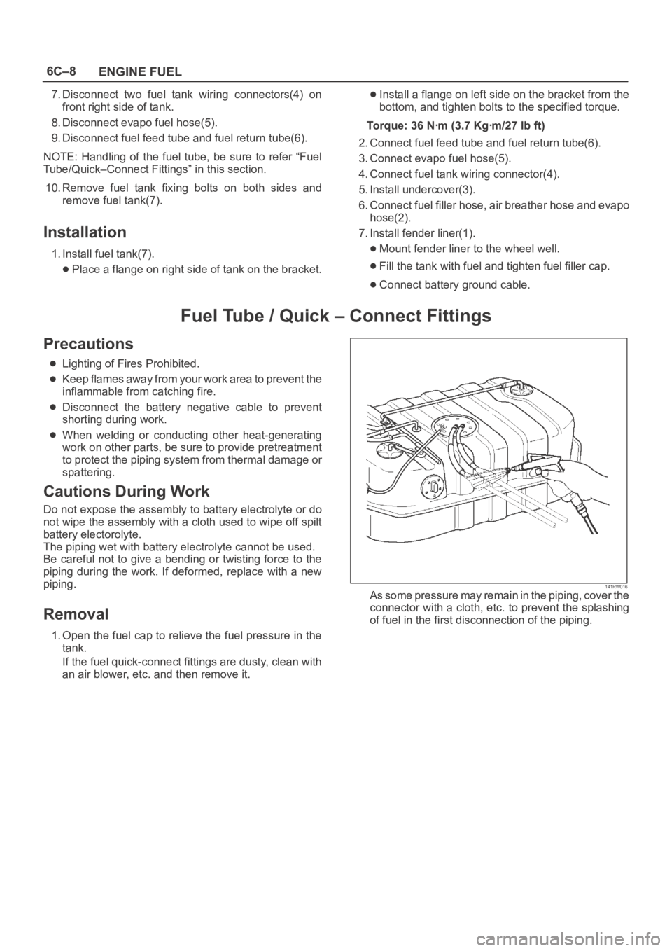
1. Open the fuel cap to relieve the fuel pressure in the
tank.
If the fuel quick-connect fittings are dusty, clean with
an air blower, etc. and then remove it.
141RW016As some pressure may remain in the piping, cover the
connector with a cloth, etc. to prevent the splashing
of fuel in the first disconnection of the piping.
Page 4616 of 6000
6C–9
ENGINE FUEL
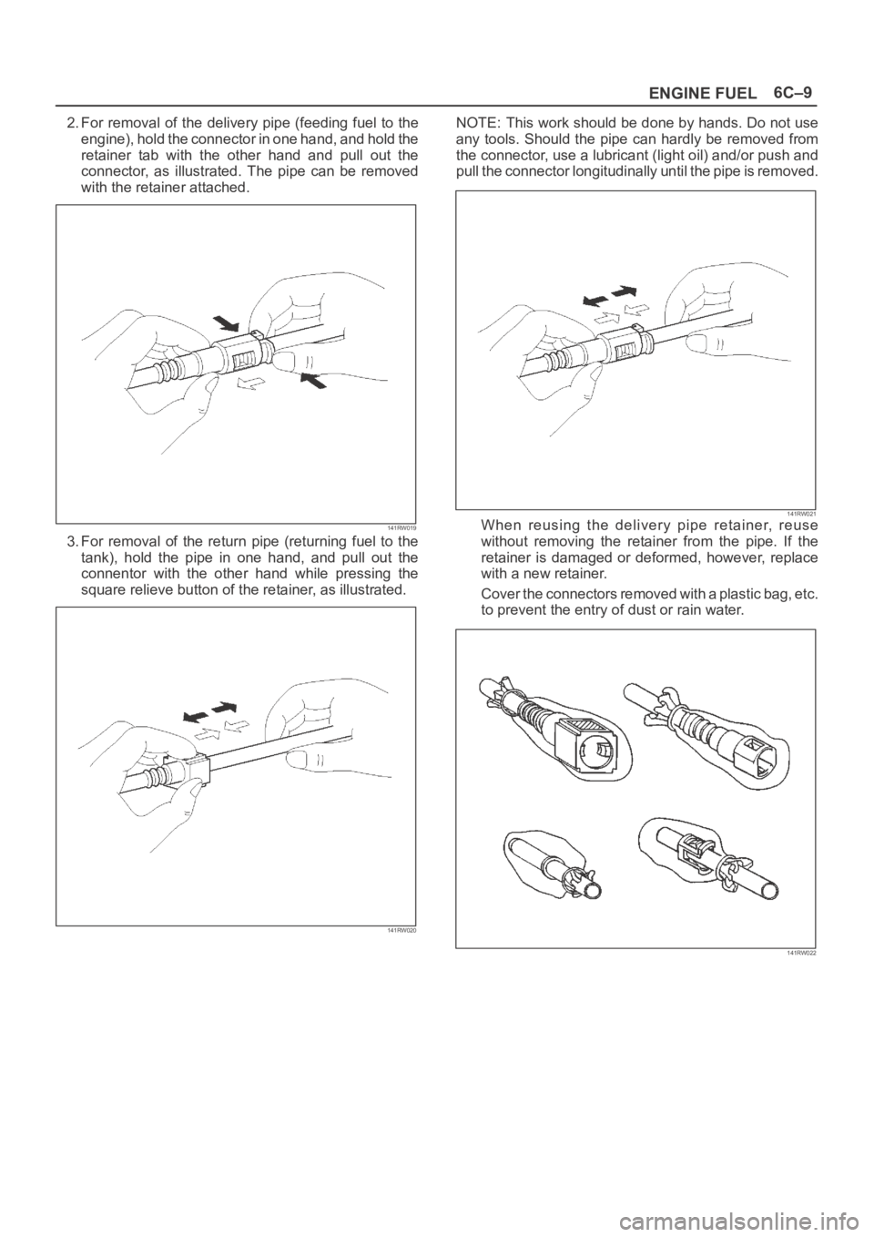
2. For removal of the delivery pipe (feeding fuel to the
engine), hold the connector in one hand, and hold the
retainer tab with the other hand and pull out the
connector, as illustrated. The pipe can be removed
with the retainer attached.
141RW019
3. For removal of the return pipe (returning fuel to the
tank), hold the pipe in one hand, and pull out the
connentor with the other hand while pressing the
square relieve button of the retainer, as illustrated.
141RW020
NOTE: This work should be done by hands. Do not use
any tools. Should the pipe can hardly be removed from
the connector, use a lubricant (light oil) and/or push and
pull the connector longitudinally until the pipe is removed.
141RW021When reusing the delivery pipe retainer, reuse
without removing the retainer from the pipe. If the
retainer is damaged or deformed, however, replace
with a new retainer.
Cover the connectors removed with a plastic bag, etc.
to prevent the entry of dust or rain water.
141RW022