1998 OPEL FRONTERA light
[x] Cancel search: lightPage 4011 of 6000
4A2B–4DIFFERENTIAL (REAR 244mm)
Diagnosis
Many noises that seem to come from the rear axle
actually originate from other sources such as tires, road
surface, wheel bearings, engine, transmission, muffler, or
body drumming. Investigate to find the source of the
noise before disassembling the rear axle. Rear axles, like
any other mechanical device, are not absolutely quiet but
should be considered quiet unless some abnormal noise
is present.
To make a systematic check for axle noise, observe the
following:
1. Select a level asphalt road to reduce tire noise and
body drumming.
2. Check rear axle lubricant level to assure correct level,
and then drive the vehicle far enough to thoroughly
warm up the rear axle lubricant.
3. Note the speed at which noise occurs. Stop the
vehicle and put the transmission in neutral. Run the
engine speed slowly up and down to determine if the
noise is caused by exhaust, muffler noise, or other
engine conditions.
4. Tire noise changes with different road surfaces; axle
noises do not. Temporarily inflate all tires to 344 kPa
(3.5kg/cm
2, 50 psi) (for test purposes only). This will
change noise caused by tires but will not affect noise
caused by the rear axle.
Rear axle noise usually stops when coasting at
speeds under 48 km/h (30 mph); however, tire noise
continues with a lower tone. Rear axle noise usually
changes when comparing pull and coast, but tire
noise stays about the same.
Distinguish between tire noise and rear axle noise by
noting if the noise changes with various speeds or
sudden acceleration and deceleration. Exhaust and
axle noise vary under these conditions, while tire
noise remains constant and is more pronounced at
speeds of 32 to 48 km/h (20 to 30 mph). Further check
for tire noise by driving the vehicle over smooth
pavements or dirt roads (not gravel) with the tires at
normal pressure. If the noise is caused by tires, it will
change noticeably with changes in road surface.
5. Loose or rough front wheel bearings will cause noise
which may be confused with rear axle noise; however,
front wheel bearing noise does not change when
comparing drive and coast. Light application of the
brake while holding vehicle speed steady will often
cause wheel bearing noise to diminish. Front wheel
bearings may be checked for noise by jacking up the
wheels and spinning them or by shaking the wheels to
determine if bearings are loose.
6. Rear suspension rubber bushings and spring
insulators dampen out rear axle noise when correctly
installed. Check to see that there is no link or rod
loosened or metal–to–metal contact.
7. Make sure that there is no metal–to–metal contact
between the floor and the frame.
After the noise has been determined to be in the axle, the
type of axle noise should be determined, in order to make
any necessary repairs.
Gear Noise
Gear noise (whine) is audible from 32 to 89 km/h (20 to 55
mph) under four driving conditions.
1. Driving under acceleration or heavy pull.
2. Driving under load or under constant speed.
3. When using enough throttle to keep the vehicle from
driving the engine while the vehicle slows down
gradually (engine still pulls slightly).
4. When coasting with the vehicle in gear and the throttle
closed. The gear noise is usually more noticeable
between 48 and 64 km/h (30 and 40 mph) and 80 and
89 km/h (50 and 55 mph).
Bearing Noise
Bad bearings generally produce a rough growl or grating
sound, rather than the whine typical of gear noise.
Bearing noise frequently “wow–wows” at bearing rpm,
indicating a bad pinion or rear axle side bearing. This
noise can be confused with rear wheel bearing noise.
Rear Wheel Bearing Noise
Rear wheel bearing noise continues to be heard while
coasting at low speed with transmission in neutral. Noise
may diminish by gentle braking. Jack up the rear wheels,
spin them by hand and listen for noise at the hubs.
Replace any faulty wheel bearings.
Knock At Low Speeds
Low speed knock can be caused by worn universal joints
or a side gear hub counter bore in the cage that is worn
oversize. Inspect and replace universal joints or cage and
side gears as required.
Backlash Clunk
Excessive clunk on acceleration and deceleration can be
caused by a worn rear axle pinion shaft, a worn cage,
excessive clearance between the axle and the side gear
splines, excessive clearance between the side gear hub
and the counterbore in the cage, worn pinion and side
gear teeth, worn thrust washers, or excessive drive pinion
and ring gear backlash. Remove worn parts and replace
as required. Select close–fitting parts when possible.
Adjust pinion and ring gear backlash.
Page 4015 of 6000
4A2B–8DIFFERENTIAL (REAR 244mm)
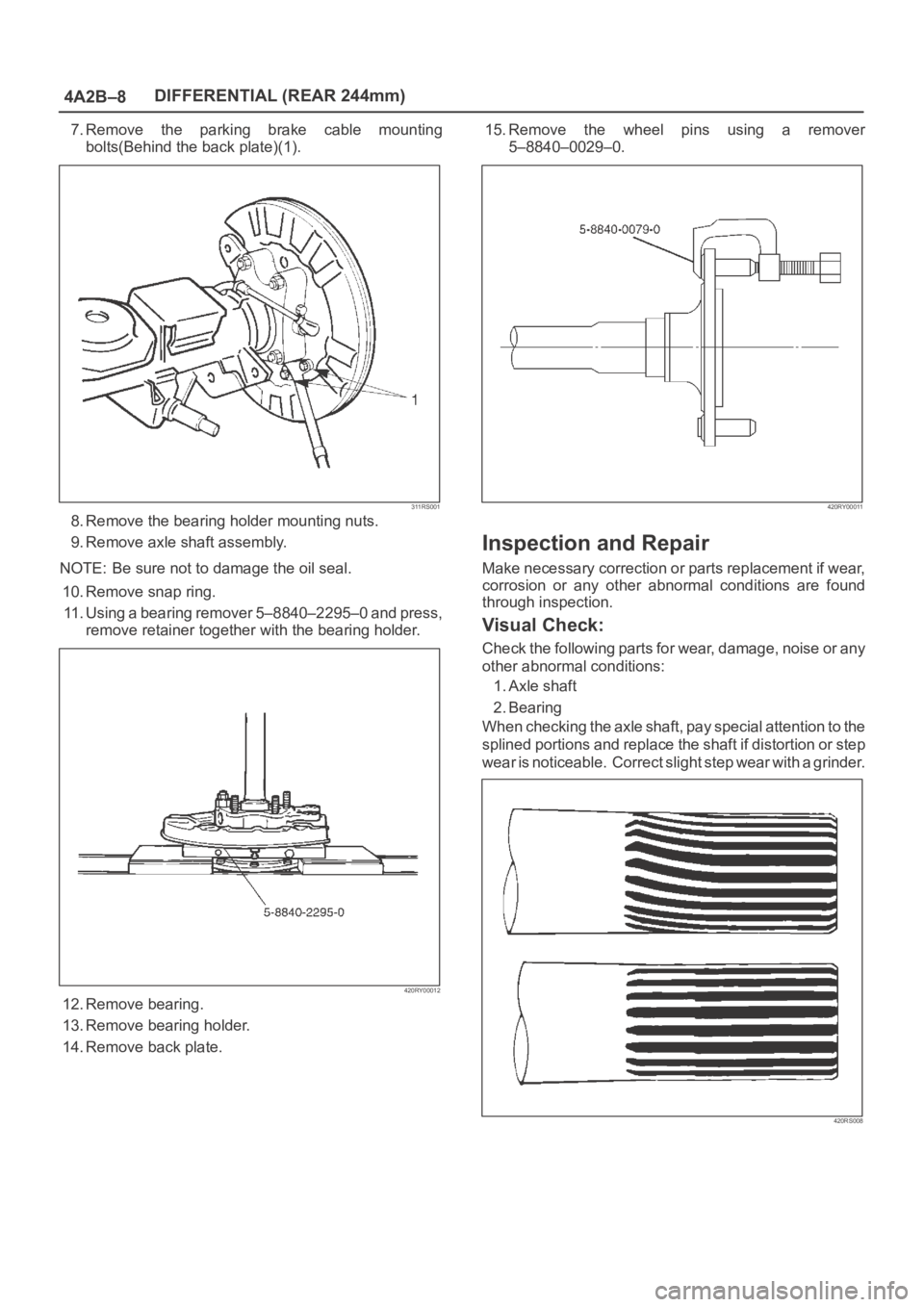
7.Remove the parking brake cable mounting
bolts(Behind the back plate)(1).
311RS001
8. Remove the bearing holder mounting nuts.
9. Remove axle shaft assembly.
NOTE: Be sure not to damage the oil seal.
10. Remove snap ring.
11. Using a bearing remover 5–8840–2295–0 and press,
remove retainer together with the bearing holder.
420RY00012
12. Remove bearing.
13. Remove bearing holder.
14. Remove back plate.15. Remove the wheel pins using a remover
5–8840–0029–0.
420RY00011
Inspection and Repair
Make necessary correction or parts replacement if wear,
corrosion or any other abnormal conditions are found
through inspection.
Visual Check:
Check the following parts for wear, damage, noise or any
other abnormal conditions:
1. Axle shaft
2. Bearing
When checking the axle shaft, pay special attention to the
splined portions and replace the shaft if distortion or step
wear is noticeable. Correct slight step wear with a grinder.
420RS008
Page 4037 of 6000
4A2B–30DIFFERENTIAL (REAR 244mm)
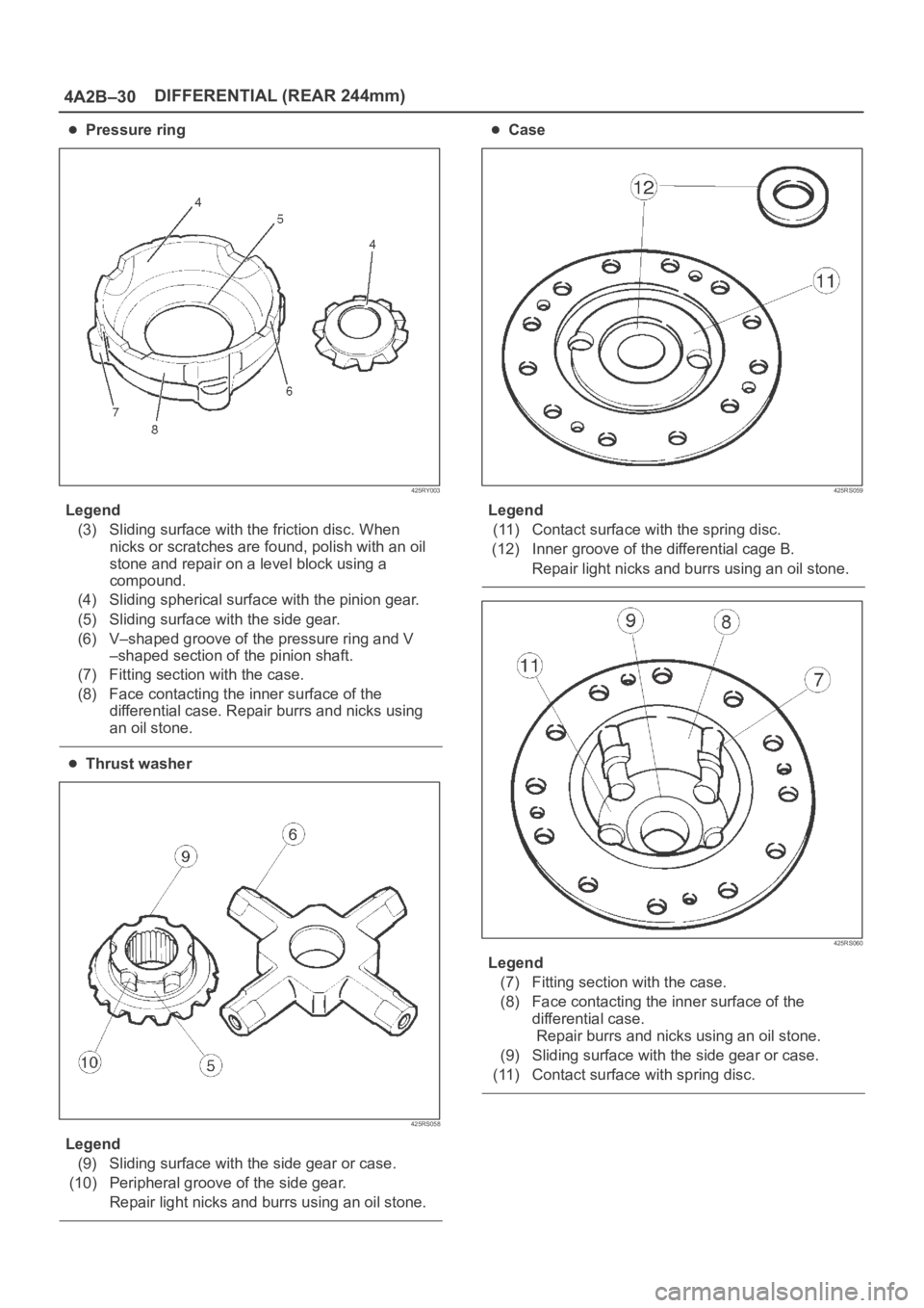
Pressure ring
425RY003
Legend
(3) Sliding surface with the friction disc. When
nicks or scratches are found, polish with an oil
stone and repair on a level block using a
compound.
(4) Sliding spherical surface with the pinion gear.
(5) Sliding surface with the side gear.
(6) V–shaped groove of the pressure ring and V
–shaped section of the pinion shaft.
(7) Fitting section with the case.
(8) Face contacting the inner surface of the
differential case. Repair burrs and nicks using
an oil stone.
Thrust washer
425RS058
Legend
(9) Sliding surface with the side gear or case.
(10) Peripheral groove of the side gear.
Repair light nicks and burrs using an oil stone.
Case
425RS059
Legend
(11) Contact surface with the spring disc.
(12) Inner groove of the differential cage B.
Repair light nicks and burrs using an oil stone.
425RS060
Legend
(7) Fitting section with the case.
(8) Face contacting the inner surface of the
differential case.
Repair burrs and nicks using an oil stone.
(9) Sliding surface with the side gear or case.
(11) Contact surface with spring disc.
Page 4070 of 6000
4B1–25 DRIVE LINE CONTROL SYSTEM (SHIFT ON THE FLY)
Diagnosis of the Faults Based on the
Status of 4WD Indicator Lamp, 4WD
Switch and T/F Change Lever
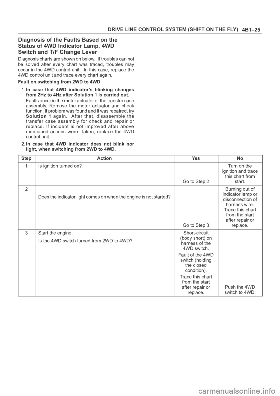
Diagnosis charts are shown on below. If troubles can not
be solved after every chart was traced, troubles may
occur in the 4WD control unit. In this case, replace the
4WD control unit and trace every chart again.
Fault on switching from 2WD to 4WD
1.In case that 4WD indicator’s blinking changes
from 2Hz to 4Hz after Solution 1 is carried out.
Faults occur in the motor actuator or the transfer case
assembly. Remove the motor actuator and check
function. If problem was found and it was repaired, try
Solution 1 again. After that, disassemble the
transfer case assembly for check and repair or
replace. If incident is not improved after above
mentioned actions were taken, replace the 4WD
control unit.
2.In case that 4WD indicator does not blink nor
light, when switching from 2WD to 4WD.
Step
ActionYe sNo
1Is ignition turned on?
Go to Step 2
Turn on the
ignition and trace
this chart from
start.
2
Does the indicator light comes on when the engine is not started?
Go to Step 3
Burning out of
indicator lamp or
disconnection of
harness wire.
Trace this chart
from the start
after repair or
replace.
3Start the engine.
Is the 4WD switch turned from 2WD to 4WD?Short-circuit
(body short) on
harness of the
4WD switch.
Fault of the 4WD
switch (holding
the closed
condition).
Trace this chart
from the start
after repair or
replace.
Push the 4WD
switch to 4WD.
Page 4075 of 6000
4B1–30
DRIVE LINE CONTROL SYSTEM (SHIFT ON THE FLY)
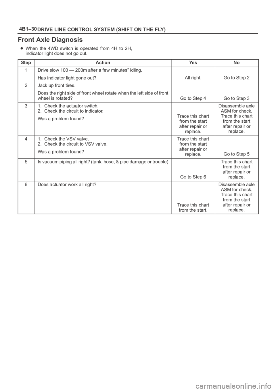
Front Axle Diagnosis
When the 4WD switch is operated from 4H to 2H,
indicator light does not go out.
Step
ActionYe sNo
1Drive slow 100 — 200m after a few minutes” idling.
Has indicator light gone out?
All right.Go to Step 2
2Jack up front tires.
Does the right side of front wheel rotate when the left side of f r o n t
wheel is rotated?
Go to Step 4Go to Step 3
31. Check the actuator switch.
2. Check the circuit to indicator.
Was a problem found?
Trace this chart
from the start
after repair or
replace.
Disassemble axle
ASM for check.
Trace this chart
from the start
after repair or
replace.
41. Check the VSV valve.
2. Check the circuit to VSV valve.
Was a problem found?Trace this chart
from the start
after repair or
replace.
Go to Step 5
5I s v a c u u m p i p i n g a l l r i g h t ? ( t a n k , h o s e , & p i p e d a m a g e o r t r o u ble)
Go to Step 6
Trace this chart
from the start
after repair or
replace.
6Does actuator work all right?
Trace this chart
from the start.
Disassemble axle
ASM for check.
Trace this chart
from the start
after repair or
replace.
Page 4076 of 6000
4B1–31 DRIVE LINE CONTROL SYSTEM (SHIFT ON THE FLY)
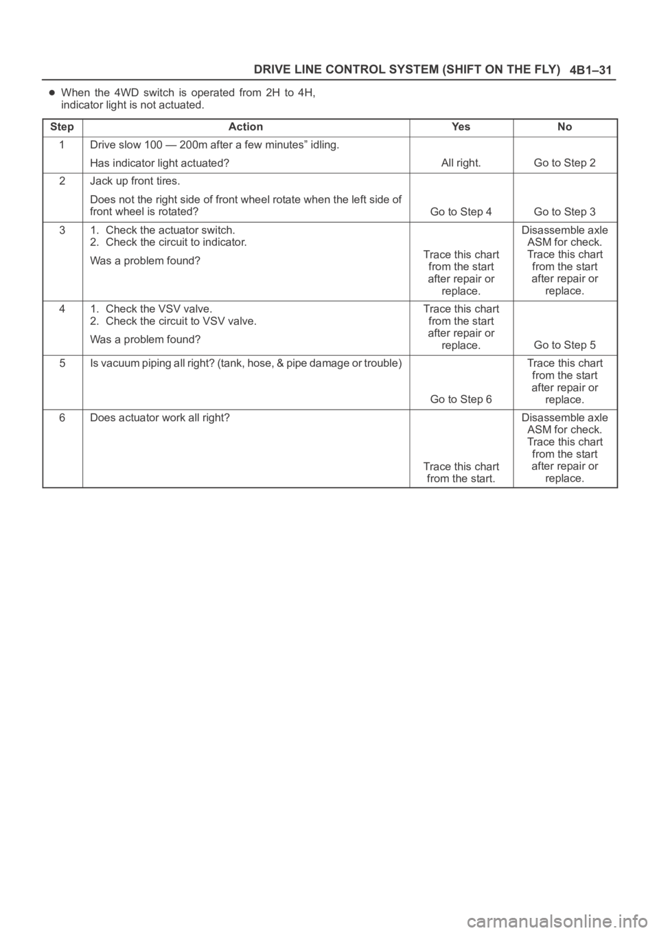
When the 4WD switch is operated from 2H to 4H,
indicator light is not actuated.
Step
ActionYe sNo
1Drive slow 100 — 200m after a few minutes” idling.
Has indicator light actuated?
All right.Go to Step 2
2Jack up front tires.
Does not the right side of front wheel rotate when the left side of
front wheel is rotated?
Go to Step 4Go to Step 3
31. Check the actuator switch.
2. Check the circuit to indicator.
Was a problem found?
Trace this chart
from the start
after repair or
replace.
Disassemble axle
ASM for check.
Trace this chart
from the start
after repair or
replace.
41. Check the VSV valve.
2. Check the circuit to VSV valve.
Was a problem found?Trace this chart
from the start
after repair or
replace.
Go to Step 5
5I s v a c u u m p i p i n g a l l r i g h t ? ( t a n k , h o s e , & p i p e d a m a g e o r t r o u ble)
Go to Step 6
Trace this chart
from the start
after repair or
replace.
6Does actuator work all right?
Trace this chart
from the start.
Disassemble axle
ASM for check.
Trace this chart
from the start
after repair or
replace.
Page 4096 of 6000
4B2–13 DRIVE LINE CONTROL SYSTEM (TOD)
Diagnosis
General Information Diagnosis
The troubles on TOD are classified into the group that can
be identified by the lighting status of the TOD indicator
lamps and those that can be recognized as abnormal
phenomena of the vehicle by the driver.
The troubles that can be identified by the lighting status of
the TOD indicator lamps are examined by the procedures
“Diagnosis from Trouble Codes” and “Trouble Diagnosis
Depending on The Status of TOD indicator”. The troubles
that can be recognized as abnormal phenomena of the
vehicle by the driver are examined by the procedure
“Diagnosis from symptom”.
Self-diagnosis
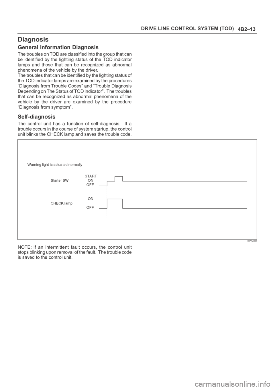
The control unit has a function of self-diagnosis. If a
trouble occurs in the course of system startup, the control
unit blinks the CHECK lamp and saves the trouble code.
C07RW021
NOTE: If an intermittent fault occurs, the control unit
stops blinking upon removal of the fault. The trouble code
is saved to the control unit.
Page 4099 of 6000
DRIVE LINE CONTROL SYSTEM (TOD) 4B2–16
7. Slowly start the vehicle in the 4L mode, and
accelerate to at least 20 km/h. Apply the brake to
completely stop the vehicle.
If the CHECK lamp starts blinking during the test run, read
the trouble codes and give appropriate maintenance
according to the diagnostic procedure. If the TOD
indicator lamps are lit abnormally during the run, check
the lighting condition and give appropriate maintenance
according to the diagnostic procedure. Even if the
phenomena are not observed, try to reproduce the
abnormal state reported by the customer to the possible
extent.
Post-Repair Check
As long as the starter is not turned off, the TOD indicator
lamps continue blinking even after the failed portion
repaired. Therefore, upon completion of repair, be sure to
turn off the starter switch once and then turn on it to
conduct the test run sequence specified in steps 1
through 7 above and check that the TOD indicator lamps
no longer show any faulty status.