Page 3205 of 6000
8F–10BODY STRUCTURE
Parts Location (W/Rear Combination Light and License Light)
690RW010
Legend
(1) Back Bar
(2) Rear Combination Light Back Plate
(3) Rear Bumper Retainer
(4) Reinforce Assembly
(5) Rear Bumper Slider Brackets
(6) Rear Combination Light Assembly
(7) License Light
(8) Reinforce Lower Screws(9) Reinforce Upper Bolts
(10) Rear Step
(11) Rear Step Clips
(12) Rear Bumper Fascia Bracket Screws
(13) Rear Bumper Assembly
(14) Rear Bumper Side Covers
(15) Rear Bumper Fascia Brackets
(16) Mud Flaps
(17) Rear Bumper Assembly Fixing Bolts
Removal
1. Disconnect battery ground cable.
2. Remove rear bumper side covers.3. Remove mud flaps.Remove three screws.
4. Remove rear bumper fascia bracket screws.
Page 3206 of 6000

8F–11 BODY STRUCTURE
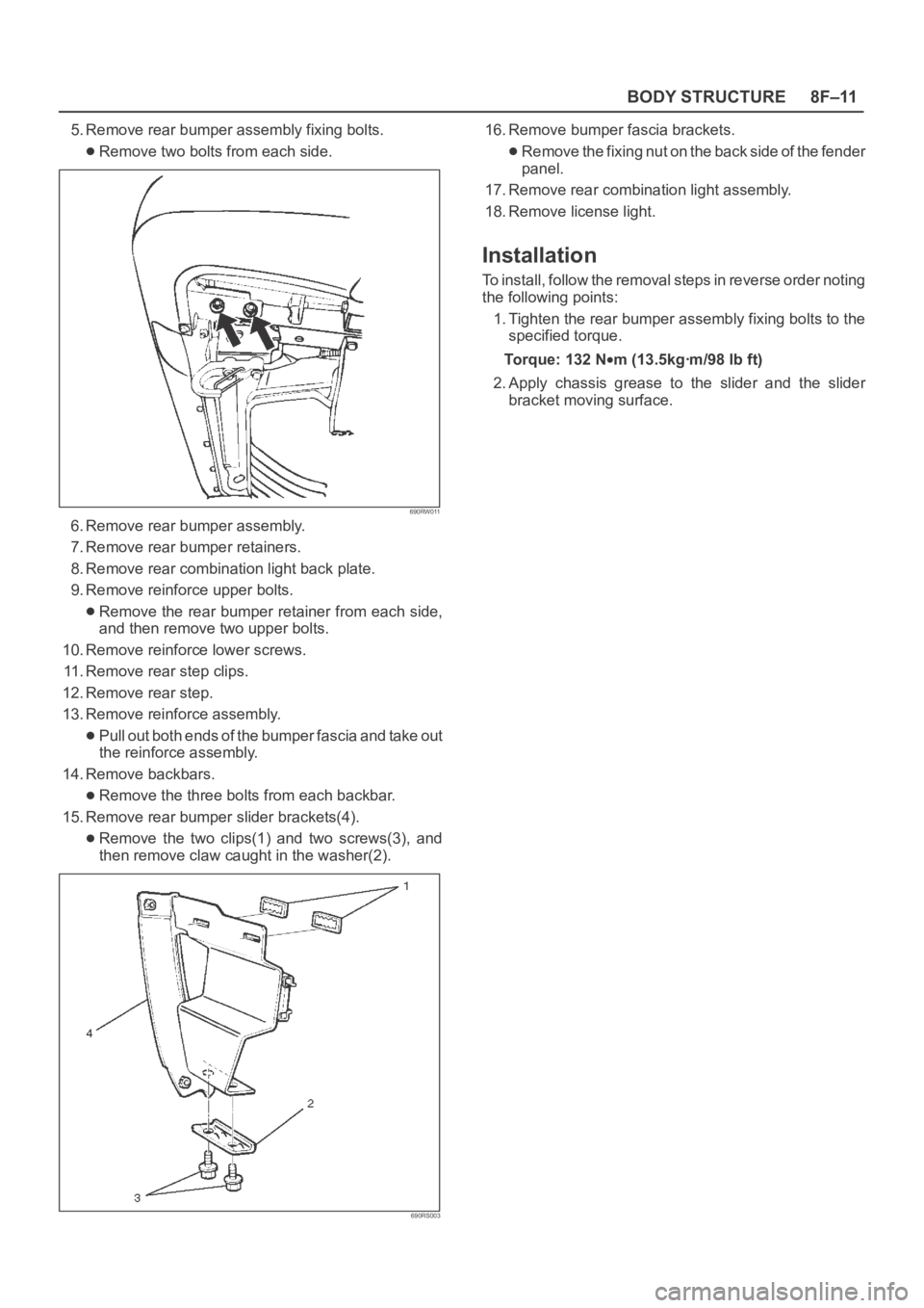
5. Remove rear bumper assembly fixing bolts.
Remove two bolts from each side.
690RW011
6. Remove rear bumper assembly.
7. Remove rear bumper retainers.
8. Remove rear combination light back plate.
9. Remove reinforce upper bolts.
Remove the rear bumper retainer from each side,
and then remove two upper bolts.
10. Remove reinforce lower screws.
11. Remove rear step clips.
12. Remove rear step.
13. Remove reinforce assembly.
Pull out both ends of the bumper fascia and take out
the reinforce assembly.
14. Remove backbars.
Remove the three bolts from each backbar.
15. Remove rear bumper slider brackets(4).
Remove the two clips(1) and two screws(3), and
then remove claw caught in the washer(2).
690RS003
16. Remove bumper fascia brackets.
Remove the fixing nut on the back side of the fender
panel.
17. Remove rear combination light assembly.
18. Remove license light.
Installation
To install, follow the removal steps in reverse order noting
the following points:
1. Tighten the rear bumper assembly fixing bolts to the
specified torque.
To r q u e : 1 3 2 N
m (13.5kgꞏm/98 lb ft)
2. Apply chassis grease to the slider and the slider
bracket moving surface.
Page 3207 of 6000
8F–12BODY STRUCTURE
Parts Location (W/Rear Combination Light)
690RW012
Legend
(1) Back Bar
(2) Rear Combination Light Back Plate
(3) Rear Bumper Retainer
(4) Reinforce Assembly
(5) Rear Bumper Slider Brackets
(6) Rear Combination Light Assembly
(7) Rear Step Clips
(8) Reinforce Upper Bolts(9) Reinforce Lower Screws
(10) Rear Bumper Fascia Bracket Screws
(11) Rear Bumper Assembly
(12) Rear Bumper Side Covers
(13) Rear Bumper Fascia Brackets
(14) Mud Flaps
(15) Clips
(16) Rear Bumper Assembly Fixing Bolts
Removal
1. Disconnect battery ground cable.
2. Remove rear bumper side covers.3. Remove mud flaps.Remove three screws.
4. Remove rear bumper fascia bracket screws.
Page 3208 of 6000

8F–13 BODY STRUCTURE
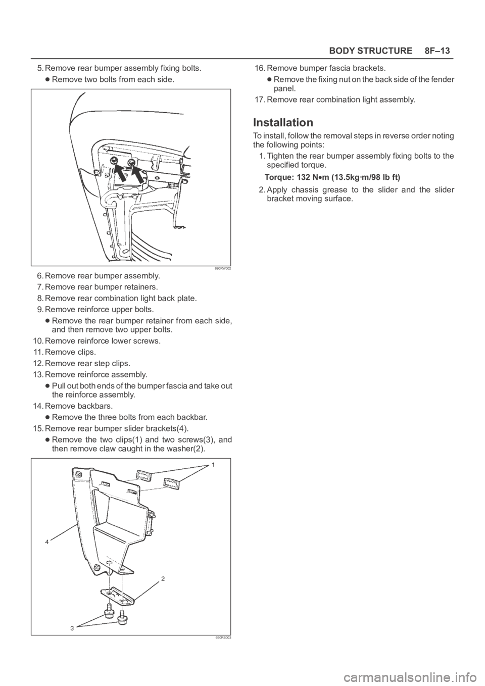
5. Remove rear bumper assembly fixing bolts.
Remove two bolts from each side.
690RW002
6. Remove rear bumper assembly.
7. Remove rear bumper retainers.
8. Remove rear combination light back plate.
9. Remove reinforce upper bolts.
Remove the rear bumper retainer from each side,
and then remove two upper bolts.
10. Remove reinforce lower screws.
11. Remove clips.
12. Remove rear step clips.
13. Remove reinforce assembly.
Pull out both ends of the bumper fascia and take out
the reinforce assembly.
14. Remove backbars.
Remove the three bolts from each backbar.
15. Remove rear bumper slider brackets(4).
Remove the two clips(1) and two screws(3), and
then remove claw caught in the washer(2).
690RS003
16. Remove bumper fascia brackets.
Remove the fixing nut on the back side of the fender
panel.
17. Remove rear combination light assembly.
Installation
To install, follow the removal steps in reverse order noting
the following points:
1. Tighten the rear bumper assembly fixing bolts to the
specified torque.
To r q u e : 1 3 2 N
m (13.5kgꞏm/98 lb ft)
2. Apply chassis grease to the slider and the slider
bracket moving surface.
Page 3215 of 6000
8F–20BODY STRUCTURE
Installation
To install, follow the removal steps in reverse order noting
the following points:
1. Reroute the control cable to its original position, and
check and see if the lock assembly and control lever
work normally.2. Tighten the hood lock assembly fixing bolts to the
specified torque.
Torque : 10 Nm (1.0kgꞏm/87 lb in)
Radiator Grille And Front End Lower Panel
Parts Location
603RW014
Legend
(1) Front End Lower Panel(2) Head light Wiper
(3) Radiator Grille
Removal
1. Open the hood.
2. Support the hood.
3. Remove headlight wiper.
Refer to Wiper/Washer System in this section.
Page 3217 of 6000
8F–22BODY STRUCTURE
Front Fender Panel
Parts Location
605RW008
Legend
(1) Cowl Cover
(2) Front Mud Flap
(3) Antenna Bezel(4) Side Flasher Light
(5) Front Fender Panel
(6) Front Combination Lamp Assembly
(7) Inner Liner
Removal
1. Open the hood.
2. Support the hood.
3. Disconnect the battery ground cable.
4. Remove cowl cover.
Refer to Cowl Cover in this section.
5. Remove front combination lamp assembly.
Disconnect fixing screw and connector.6. Remove front mud flap.
Disconnect three fixing screws and four clips.
7. Remove inner liner.
8. Remove antenna bezel.
Refer to Entertainment in this section.
9. Remove side flasher light.
Refer to Lighting System in this section.
Page 3244 of 6000
8F–49 BODY STRUCTURE
Removal
CAUTION: For precautions on installation or
removal of SRS—air bag system, refer to
Supplemental Restraint System (SRS) — AIR BAG in
Restraint section.
1. Disconnect the battery ground cable.
2. Remove front console assembly.
Remove the 4 fixing screws and disconnect the
switch connectors.
3. Remove lower cluster assembly.
Remove the 3 fixing screws (1) in order to
disconnect the cigarette lighter (3) and the
illumination (2) connectors.
740RS014
4. Remove glove box.
Remove the 2 fixing screws.
740RW104
5. Remove instrument panel passenger lower cover
assembly.
Remove the 7 fixing screws (1) and 1 clip (2).
740RW103
6. Remove passenger knee bolster reinforcement
assembly.
Remove the 4 fixing bolts (2) and 4 nuts (1).
740RS011
Page 3248 of 6000

8F–53 BODY STRUCTURE
Installation
To install, follow the removal steps in the reverse order.
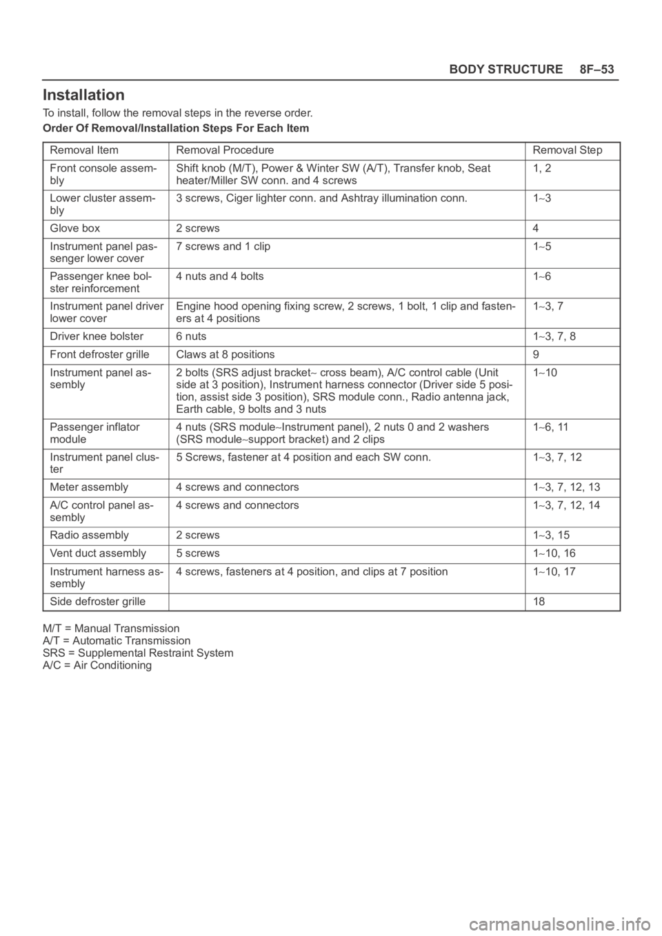
Order Of Removal/Installation Steps For Each Item
Removal Item
Removal ProcedureRemoval Step
Front console assem-
blyShift knob (M/T), Power & Winter SW (A/T), Transfer knob, Seat
heater/Miller SW conn. and 4 screws1, 2
Lower cluster assem-
bly3 screws, Ciger lighter conn. and Ashtray illumination conn.13
Glove box2 screws4
Instrument panel pas-
senger lower cover7 screws and 1 clip15
Passenger knee bol-
ster reinforcement4 nuts and 4 bolts16
Instrument panel driver
lower coverEngine hood opening fixing screw, 2 screws, 1 bolt, 1 clip and fasten-
ers at 4 positions13, 7
Driver knee bolster6 nuts13, 7, 8
Front defroster grilleClaws at 8 positions9
Instrument panel as-
sembly2 bolts (SRS adjust bracket cross beam), A/C control cable (Unit
side at 3 position), Instrument harness connector (Driver side 5 posi-
tion, assist side 3 position), SRS module conn., Radio antenna jack,
Earth cable, 9 bolts and 3 nuts110
Passenger inflator
module4 nuts (SRS moduleInstrument panel), 2 nuts 0 and 2 washers
(SRS module
support bracket) and 2 clips
16, 11
Instrument panel clus-
ter5 Screws, fastener at 4 position and each SW conn.13, 7, 12
Meter assembly4 screws and connectors13, 7, 12, 13
A/C control panel as-
sembly4 screws and connectors13, 7, 12, 14
Radio assembly2 screws13, 15
Vent duct assembly5 screws110, 16
Instrument harness as-
sembly4 screws, fasteners at 4 position, and clips at 7 position110, 17
Side defroster grille18
M/T = Manual Transmission
A/T = Automatic Transmission
SRS = Supplemental Restraint System
A/C = Air Conditioning