1998 OPEL FRONTERA light
[x] Cancel search: lightPage 3184 of 6000
METER AND GAUGE8E–7
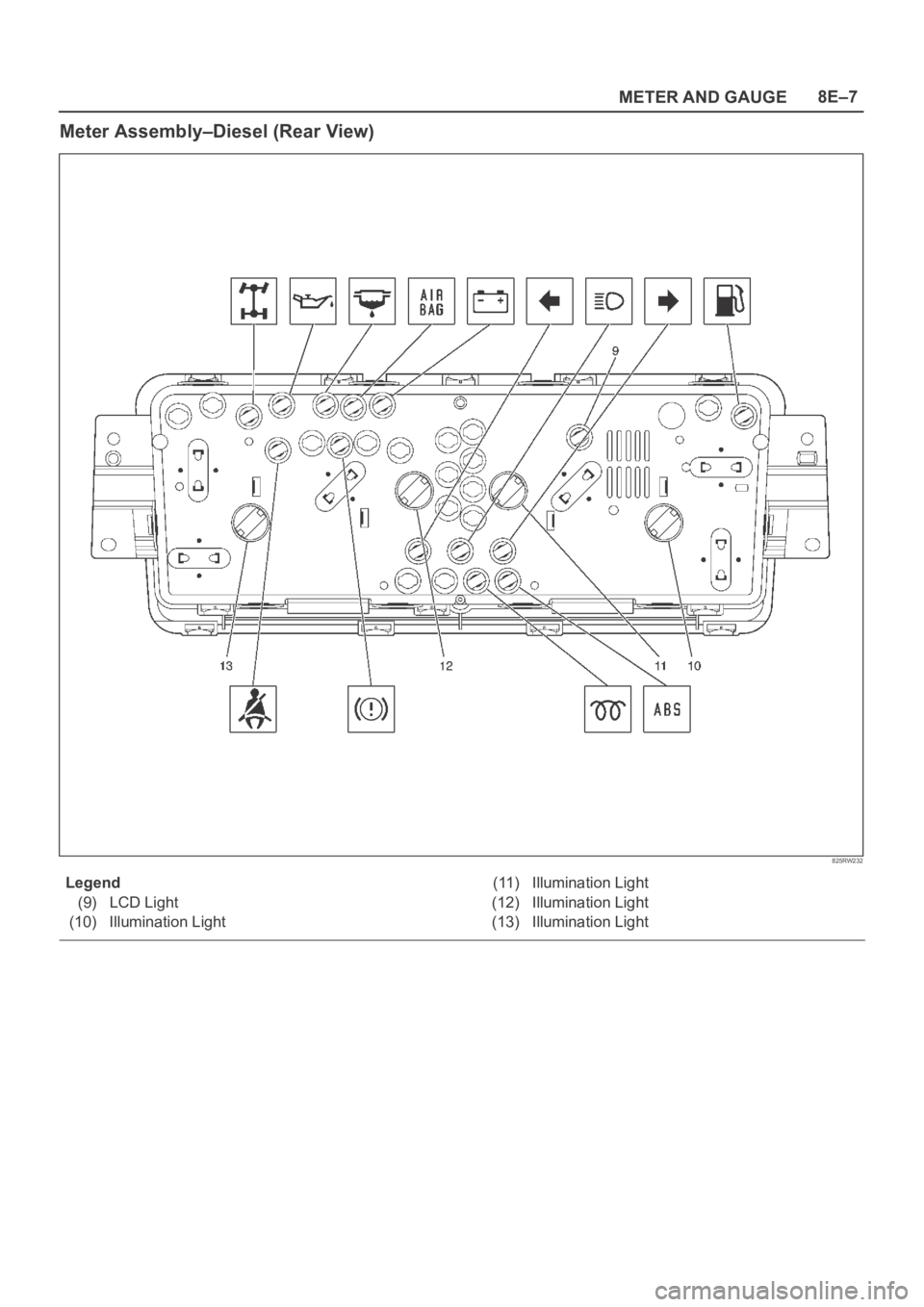
Meter Assembly–Diesel (Rear View)
825RW232
Legend
(9) LCD Light
(10) Illumination Light(11) Illumination Light
(12) Illumination Light
(13) Illumination Light
Page 3186 of 6000
METER AND GAUGE8E–9
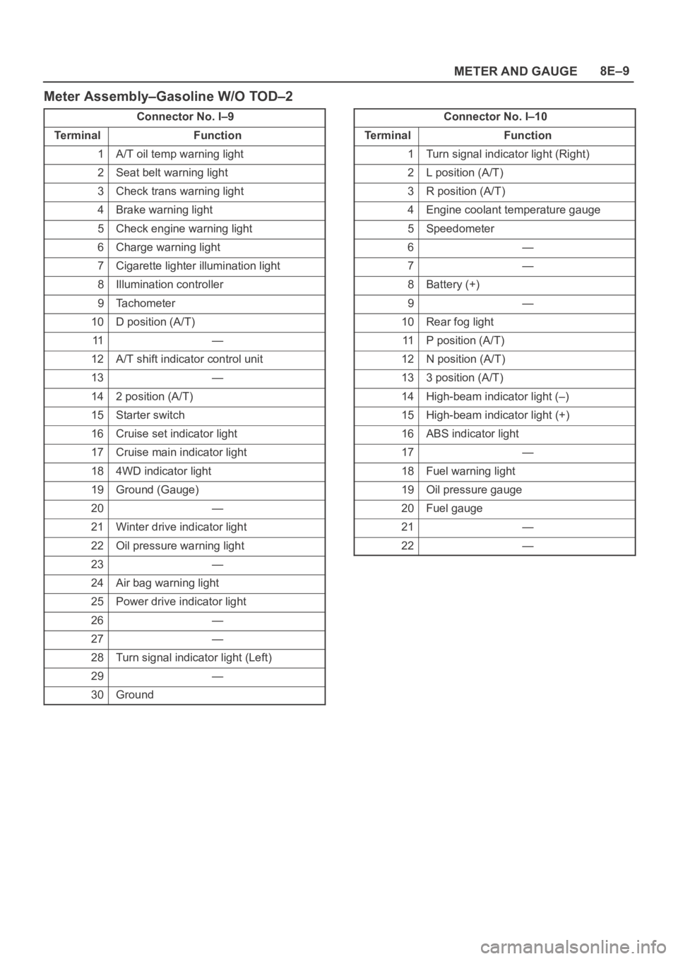
Meter Assembly–Gasoline W/O TOD–2
Connector No. I–9
Te r m i n a lFunction
1A/T oil temp warning light
2Seat belt warning light
3Check trans warning light
4Brake warning light
5Check engine warning light
6Charge warning light
7Cigarette lighter illumination light
8Illumination controller
9Tachometer
10D position (A/T)
11—
12A/T shift indicator control unit
13—
142 position (A/T)
15Starter switch
16Cruise set indicator light
17Cruise main indicator light
184WD indicator light
19Ground (Gauge)
20—
21Winter drive indicator light
22Oil pressure warning light
23—
24Air bag warning light
25Power drive indicator light
26—
27—
28Turn signal indicator light (Left)
29—
30Ground
Connector No. I–10
Te r m i n a lFunction
1Turn signal indicator light (Right)
2L position (A/T)
3R position (A/T)
4Engine coolant temperature gauge
5Speedometer
6—
7—
8Battery (+)
9—
10Rear fog light
11P position (A/T)
12N position (A/T)
133 position (A/T)
14High-beam indicator light (–)
15High-beam indicator light (+)
16ABS indicator light
17—
18Fuel warning light
19Oil pressure gauge
20Fuel gauge
21—
22—
Page 3188 of 6000
METER AND GAUGE8E–11
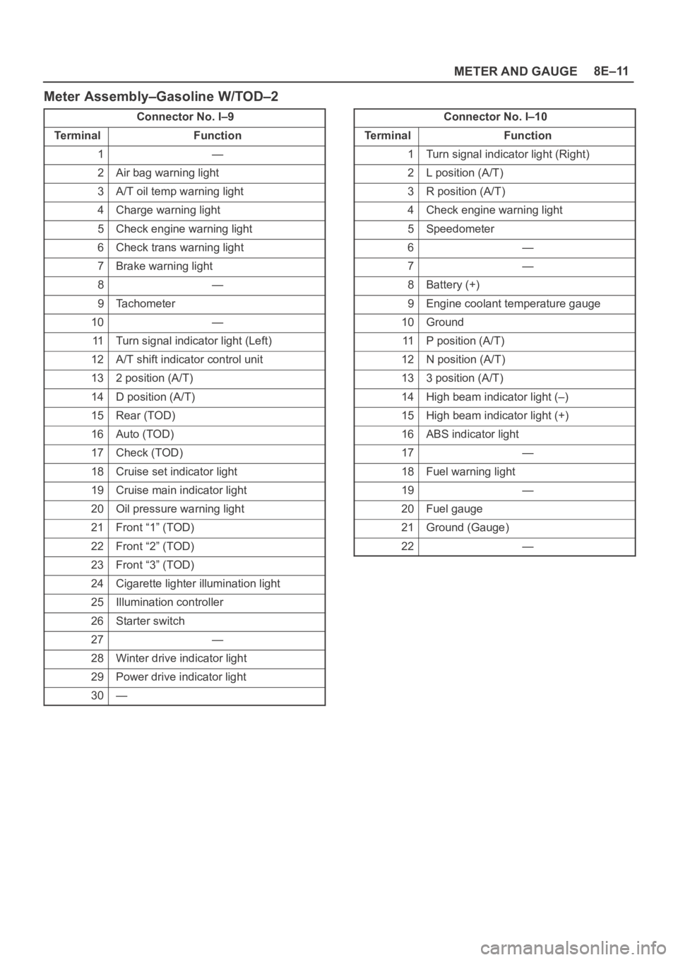
Meter Assembly–Gasoline W/TOD–2
Connector No. I–9
Te r m i n a lFunction
1—
2Air bag warning light
3A/T oil temp warning light
4Charge warning light
5Check engine warning light
6Check trans warning light
7Brake warning light
8—
9Tachometer
10—
11Turn signal indicator light (Left)
12A/T shift indicator control unit
132 position (A/T)
14D position (A/T)
15Rear (TOD)
16Auto (TOD)
17Check (TOD)
18Cruise set indicator light
19Cruise main indicator light
20Oil pressure warning light
21Front “1” (TOD)
22Front “2” (TOD)
23Front “3” (TOD)
24Cigarette lighter illumination light
25Illumination controller
26Starter switch
27—
28Winter drive indicator light
29Power drive indicator light
30—
Connector No. I–10
Te r m i n a lFunction
1Turn signal indicator light (Right)
2L position (A/T)
3R position (A/T)
4Check engine warning light
5Speedometer
6—
7—
8Battery (+)
9Engine coolant temperature gauge
10Ground
11P position (A/T)
12N position (A/T)
133 position (A/T)
14High beam indicator light (–)
15High beam indicator light (+)
16ABS indicator light
17—
18Fuel warning light
19—
20Fuel gauge
21Ground (Gauge)
22—
Page 3190 of 6000
METER AND GAUGE8E–13
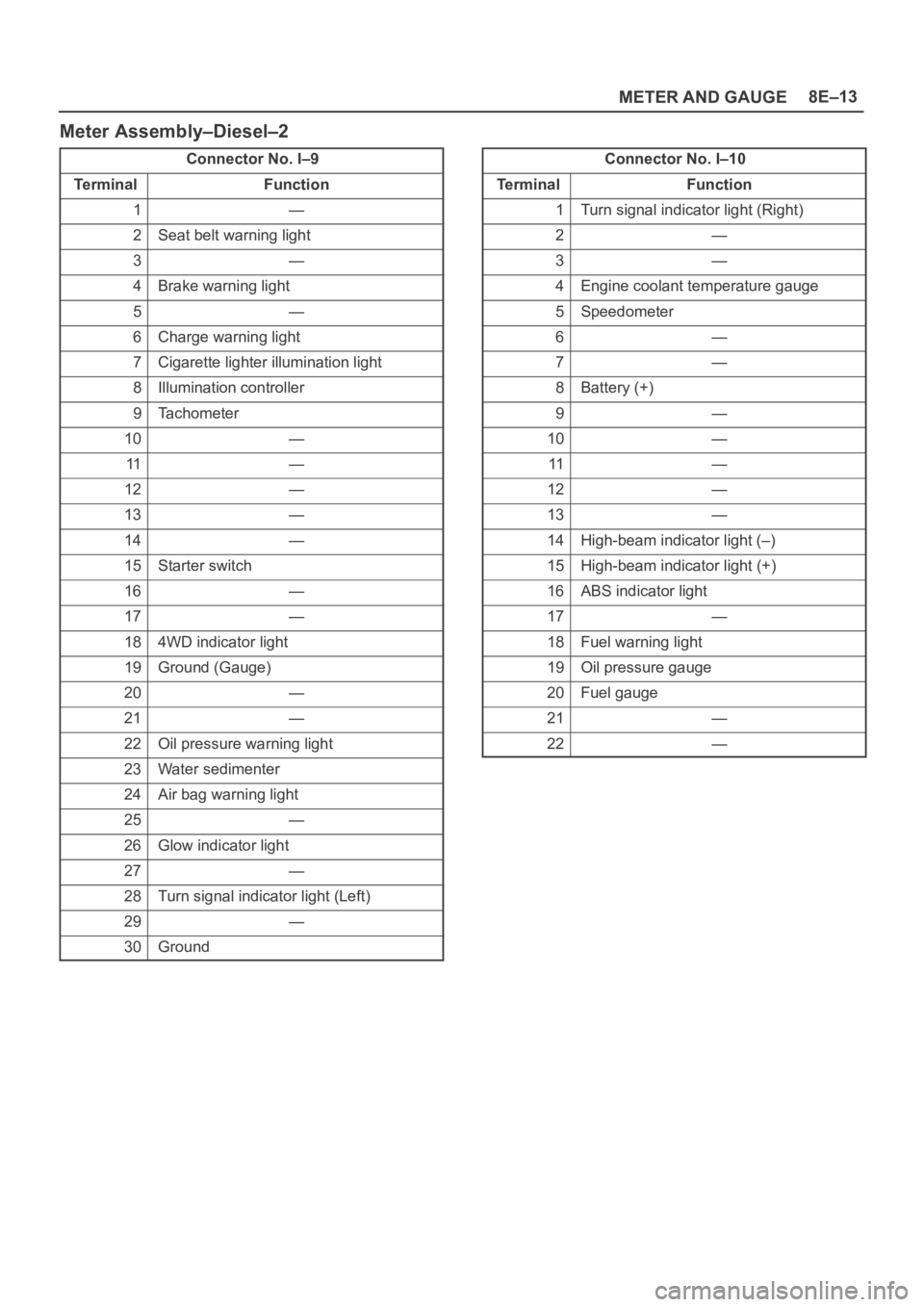
Meter Assembly–Diesel–2
Connector No. I–9
Te r m i n a lFunction
1—
2Seat belt warning light
3—
4Brake warning light
5—
6Charge warning light
7Cigarette lighter illumination light
8Illumination controller
9Tachometer
10—
11—
12—
13—
14—
15Starter switch
16—
17—
184WD indicator light
19Ground (Gauge)
20—
21—
22Oil pressure warning light
23Water sedimenter
24Air bag warning light
25—
26Glow indicator light
27—
28Turn signal indicator light (Left)
29—
30Ground
Connector No. I–10
Te r m i n a lFunction
1Turn signal indicator light (Right)
2—
3—
4Engine coolant temperature gauge
5Speedometer
6—
7—
8Battery (+)
9—
10—
11—
12—
13—
14High-beam indicator light (–)
15High-beam indicator light (+)
16ABS indicator light
17—
18Fuel warning light
19Oil pressure gauge
20Fuel gauge
21—
22—
Page 3191 of 6000
8E–14METER AND GAUGE
Removal
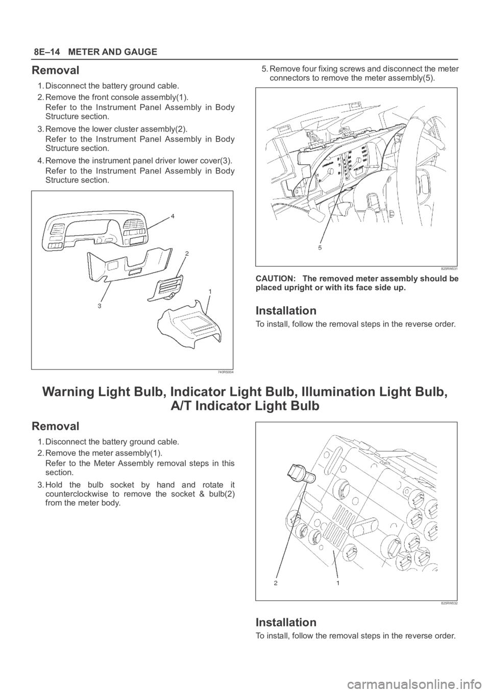
1. Disconnect the battery ground cable.
2. Remove the front console assembly(1).
Refer to the Instrument Panel Assembly in Body
Structure section.
3. Remove the lower cluster assembly(2).
Refer to the Instrument Panel Assembly in Body
Structure section.
4. Remove the instrument panel driver lower cover(3).
Refer to the Instrument Panel Assembly in Body
Structure section.
740RS004
5. Remove four fixing screws and disconnect the meter
connectors to remove the meter assembly(5).
825RW031
CAUTION: The removed meter assembly should be
placed upright or with its face side up.
Installation
To install, follow the removal steps in the reverse order.
Warning Light Bulb, Indicator Light Bulb, Illumination Light Bulb,
A/T Indicator Light Bulb
Removal
1. Disconnect the battery ground cable.
2. Remove the meter assembly(1).
Refer to the Meter Assembly removal steps in this
section.
3. Hold the bulb socket by hand and rotate it
counterclockwise to remove the socket & bulb(2)
from the meter body.
825RW032
Installation
To install, follow the removal steps in the reverse order.
Page 3196 of 6000
8F–1 BODY STRUCTURE
BODY AND ACCESSORIES
BODY STRUCTURE
CONTENTS
Service Precaution 8F–3. . . . . . . . . . . . . . . . . . . . . .
Frame 8F–3. . . . . . . . . . . . . . . . . . . . . . . . . . . . . . . . .
General Description 8F–3. . . . . . . . . . . . . . . . . . . . . .
Frame Dimensions (L W B) 8F–4. . . . . . . . . . . . . . .
Frame Dimensions (S W B) 8F–5. . . . . . . . . . . . . . .
General Description 8F–6. . . . . . . . . . . . . . . . . . . . .
Front Bumper 8F–6. . . . . . . . . . . . . . . . . . . . . . . . . . .
Parts Location 8F–6. . . . . . . . . . . . . . . . . . . . . . . .
Removal 8F–7. . . . . . . . . . . . . . . . . . . . . . . . . . . . .
Installation 8F–7. . . . . . . . . . . . . . . . . . . . . . . . . . . .
Front Bumper Slider Bracket 8F–7. . . . . . . . . . . . . .
Removal 8F–7. . . . . . . . . . . . . . . . . . . . . . . . . . . . .
Installation 8F–7. . . . . . . . . . . . . . . . . . . . . . . . . . . .
Rear Bumper 8F–8. . . . . . . . . . . . . . . . . . . . . . . . . . .
Parts Location 8F–8. . . . . . . . . . . . . . . . . . . . . . . .
Removal 8F–8. . . . . . . . . . . . . . . . . . . . . . . . . . . . .
Installation 8F–9. . . . . . . . . . . . . . . . . . . . . . . . . . . .
Parts Location (W/Rear Combination Light
and License Light) 8F–10. . . . . . . . . . . . . . . . . . . .
Removal 8F–10. . . . . . . . . . . . . . . . . . . . . . . . . . . . .
Installation 8F–11. . . . . . . . . . . . . . . . . . . . . . . . . . . .
Parts Location (W/Rear Combination Light) 8F–12
Removal 8F–12. . . . . . . . . . . . . . . . . . . . . . . . . . . . .
Installation 8F–13. . . . . . . . . . . . . . . . . . . . . . . . . . . .
Rear Bumper Slider 8F–14. . . . . . . . . . . . . . . . . . . . .
Removal 8F–14. . . . . . . . . . . . . . . . . . . . . . . . . . . . .
Installation 8F–14. . . . . . . . . . . . . . . . . . . . . . . . . . . .
General Description 8F–15. . . . . . . . . . . . . . . . . . . . .
Cowl Cover 8F–15. . . . . . . . . . . . . . . . . . . . . . . . . . . . .
Parts Location 8F–15. . . . . . . . . . . . . . . . . . . . . . . .
Removal 8F–15. . . . . . . . . . . . . . . . . . . . . . . . . . . . .
Installation 8F–16. . . . . . . . . . . . . . . . . . . . . . . . . . . .
Engine Hood 8F–16. . . . . . . . . . . . . . . . . . . . . . . . . . .
Removal 8F–16. . . . . . . . . . . . . . . . . . . . . . . . . . . . .
Installation 8F–16. . . . . . . . . . . . . . . . . . . . . . . . . . . .
Air Bulge 8F–17. . . . . . . . . . . . . . . . . . . . . . . . . . . . . . .
Parts Location 8F–17. . . . . . . . . . . . . . . . . . . . . . . .
Removal 8F–17. . . . . . . . . . . . . . . . . . . . . . . . . . . . .
Installation 8F–17. . . . . . . . . . . . . . . . . . . . . . . . . . . .
Engine Hood Hinge 8F–18. . . . . . . . . . . . . . . . . . . . . .
Parts Location 8F–18. . . . . . . . . . . . . . . . . . . . . . . .
Removal 8F–18. . . . . . . . . . . . . . . . . . . . . . . . . . . . .
Installation 8F–18. . . . . . . . . . . . . . . . . . . . . . . . . . . .
Engine Hood Lock 8F–19. . . . . . . . . . . . . . . . . . . . . . . Parts Location 8F–19. . . . . . . . . . . . . . . . . . . . . . . .
Removal 8F–19. . . . . . . . . . . . . . . . . . . . . . . . . . . . .
Installation 8F–20. . . . . . . . . . . . . . . . . . . . . . . . . . . .
Radiator Grille And Front End Lower Panel 8F–20.
Parts Location 8F–20. . . . . . . . . . . . . . . . . . . . . . . .
Removal 8F–20. . . . . . . . . . . . . . . . . . . . . . . . . . . . .
Installation 8F–21. . . . . . . . . . . . . . . . . . . . . . . . . . . .
Front Fender Panel 8F–22. . . . . . . . . . . . . . . . . . . . . .
Parts Location 8F–22. . . . . . . . . . . . . . . . . . . . . . . .
Removal 8F–22. . . . . . . . . . . . . . . . . . . . . . . . . . . . .
Installation 8F–23. . . . . . . . . . . . . . . . . . . . . . . . . . . .
Body Mounting 8F–24. . . . . . . . . . . . . . . . . . . . . . . . . .
Parts Location 8F–24. . . . . . . . . . . . . . . . . . . . . . . .
Removal (No.1 – No. 2) 8F–24. . . . . . . . . . . . . . . .
Removal (No. 3 — No. 6) 8F–25. . . . . . . . . . . . . . .
Installation 8F–26. . . . . . . . . . . . . . . . . . . . . . . . . . . .
General Description 8F–27. . . . . . . . . . . . . . . . . . . . .
Body Dimension 8F–28. . . . . . . . . . . . . . . . . . . . . . . .
Instrument Panel Assembly 8F–48. . . . . . . . . . . . . . .
Parts Location 8F–48. . . . . . . . . . . . . . . . . . . . . . . .
Removal 8F–49. . . . . . . . . . . . . . . . . . . . . . . . . . . . .
Installation 8F–53. . . . . . . . . . . . . . . . . . . . . . . . . . . .
Cross Beam Assembly 8F–54. . . . . . . . . . . . . . . . . . .
Parts Location 8F–54. . . . . . . . . . . . . . . . . . . . . . . .
Removal 8F–54. . . . . . . . . . . . . . . . . . . . . . . . . . . . .
Installation 8F–55. . . . . . . . . . . . . . . . . . . . . . . . . . . .
Front Door Assembly 8F–56. . . . . . . . . . . . . . . . . . . .
Parts Location 8F–56. . . . . . . . . . . . . . . . . . . . . . . .
Removal 8F–56. . . . . . . . . . . . . . . . . . . . . . . . . . . . .
Installation 8F–56. . . . . . . . . . . . . . . . . . . . . . . . . . . .
Rear Door Assembly 8F–57. . . . . . . . . . . . . . . . . . . . .
Parts Location 8F–57. . . . . . . . . . . . . . . . . . . . . . . .
Removal 8F–57. . . . . . . . . . . . . . . . . . . . . . . . . . . . .
Installation 8F–58. . . . . . . . . . . . . . . . . . . . . . . . . . . .
Door Strikers 8F–58. . . . . . . . . . . . . . . . . . . . . . . . . . .
Adjustment 8F–58. . . . . . . . . . . . . . . . . . . . . . . . . . .
Door Check Arm Assembly (Front & Rear) 8F–59. .
Parts Location 8F–59. . . . . . . . . . . . . . . . . . . . . . . .
Removal 8F–59. . . . . . . . . . . . . . . . . . . . . . . . . . . . .
Installation 8F–60. . . . . . . . . . . . . . . . . . . . . . . . . . . .
Front Window Regulator, Glass And Glass
Run 8F–60. . . . . . . . . . . . . . . . . . . . . . . . . . . . . . . . . . .
Parts Location 8F–60. . . . . . . . . . . . . . . . . . . . . . . .
Removal 8F–60. . . . . . . . . . . . . . . . . . . . . . . . . . . . .
Page 3201 of 6000
8F–6BODY STRUCTURE
General Description
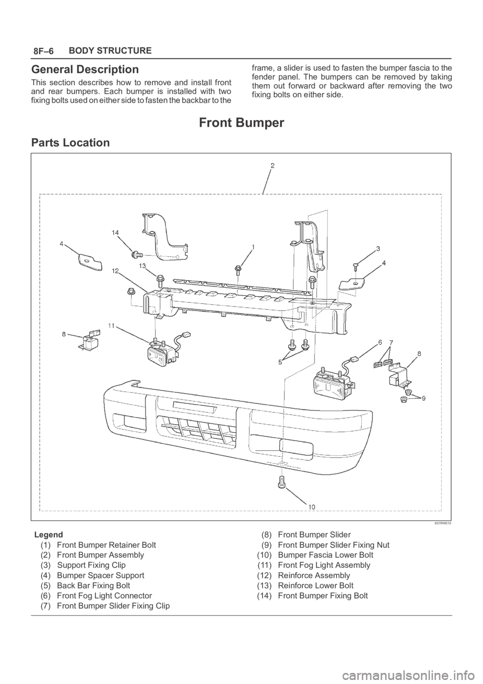
This section describes how to remove and install front
and rear bumpers. Each bumper is installed with two
fixing bolts used on either side to fasten the backbar to theframe, a slider is used to fasten the bumper fascia to the
fender panel. The bumpers can be removed by taking
them out forward or backward after removing the two
fixing bolts on either side.
Front Bumper
Parts Location
601RW015
Legend
(1) Front Bumper Retainer Bolt
(2) Front Bumper Assembly
(3) Support Fixing Clip
(4) Bumper Spacer Support
(5) Back Bar Fixing Bolt
(6) Front Fog Light Connector
(7) Front Bumper Slider Fixing Clip(8) Front Bumper Slider
(9) Front Bumper Slider Fixing Nut
(10) Bumper Fascia Lower Bolt
(11) Front Fog Light Assembly
(12) Reinforce Assembly
(13) Reinforce Lower Bolt
(14) Front Bumper Fixing Bolt
Page 3202 of 6000
8F–7 BODY STRUCTURE
Removal
1. Disconnect battery ground cable.
2. Remove front fog light connector.
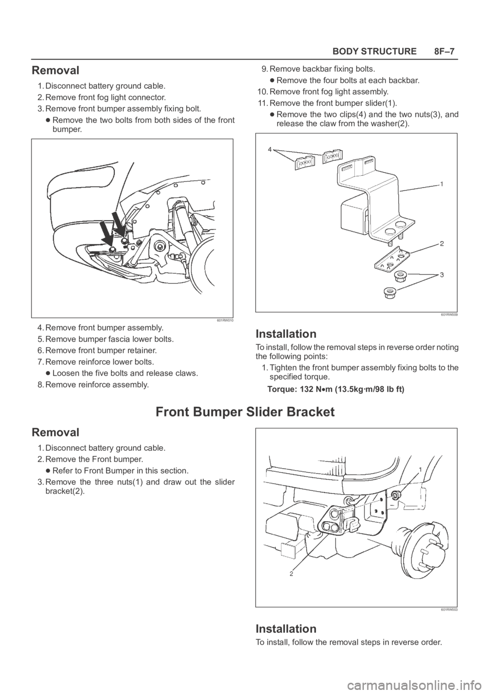
3. Remove front bumper assembly fixing bolt.
Remove the two bolts from both sides of the front
bumper.
601RW010
4. Remove front bumper assembly.
5. Remove bumper fascia lower bolts.
6. Remove front bumper retainer.
7. Remove reinforce lower bolts.
Loosen the five bolts and release claws.
8. Remove reinforce assembly.9. Remove backbar fixing bolts.
Remove the four bolts at each backbar.
10. Remove front fog light assembly.
11. Remove the front bumper slider(1).
Remove the two clips(4) and the two nuts(3), and
release the claw from the washer(2).
601RW009
Installation
To install, follow the removal steps in reverse order noting
the following points:
1. Tighten the front bumper assembly fixing bolts to the
specified torque.
To r q u e : 1 3 2 N
m (13.5kgꞏm/98 lb ft)
Front Bumper Slider Bracket
Removal
1. Disconnect battery ground cable.
2. Remove the Front bumper.
Refer to Front Bumper in this section.
3. Remove the three nuts(1) and draw out the slider
bracket(2).
601RW003
Installation
To install, follow the removal steps in reverse order.