1998 OPEL FRONTERA clutch
[x] Cancel search: clutchPage 4524 of 6000
6A–28
ENGINE MECHANICAL
Crankshaft Pulley
Removal
1. Disconnect battery ground cable.
2. Remove air cleaner assembly.
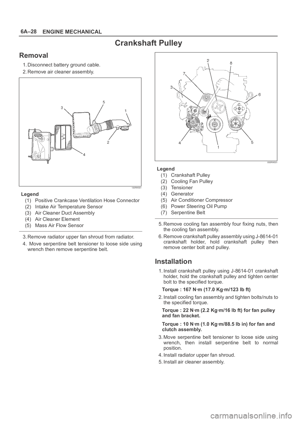
130RW001
Legend
(1) Positive Crankcase Ventilation Hose Connector
(2) Intake Air Temperature Sensor
(3) Air Cleaner Duct Assembly
(4) Air Cleaner Element
(5) Mass Air Flow Sensor
3. Remove radiator upper fan shroud from radiator.
4. Move serpentine belt tensioner to loose side using
wrench then remove serpentine belt.
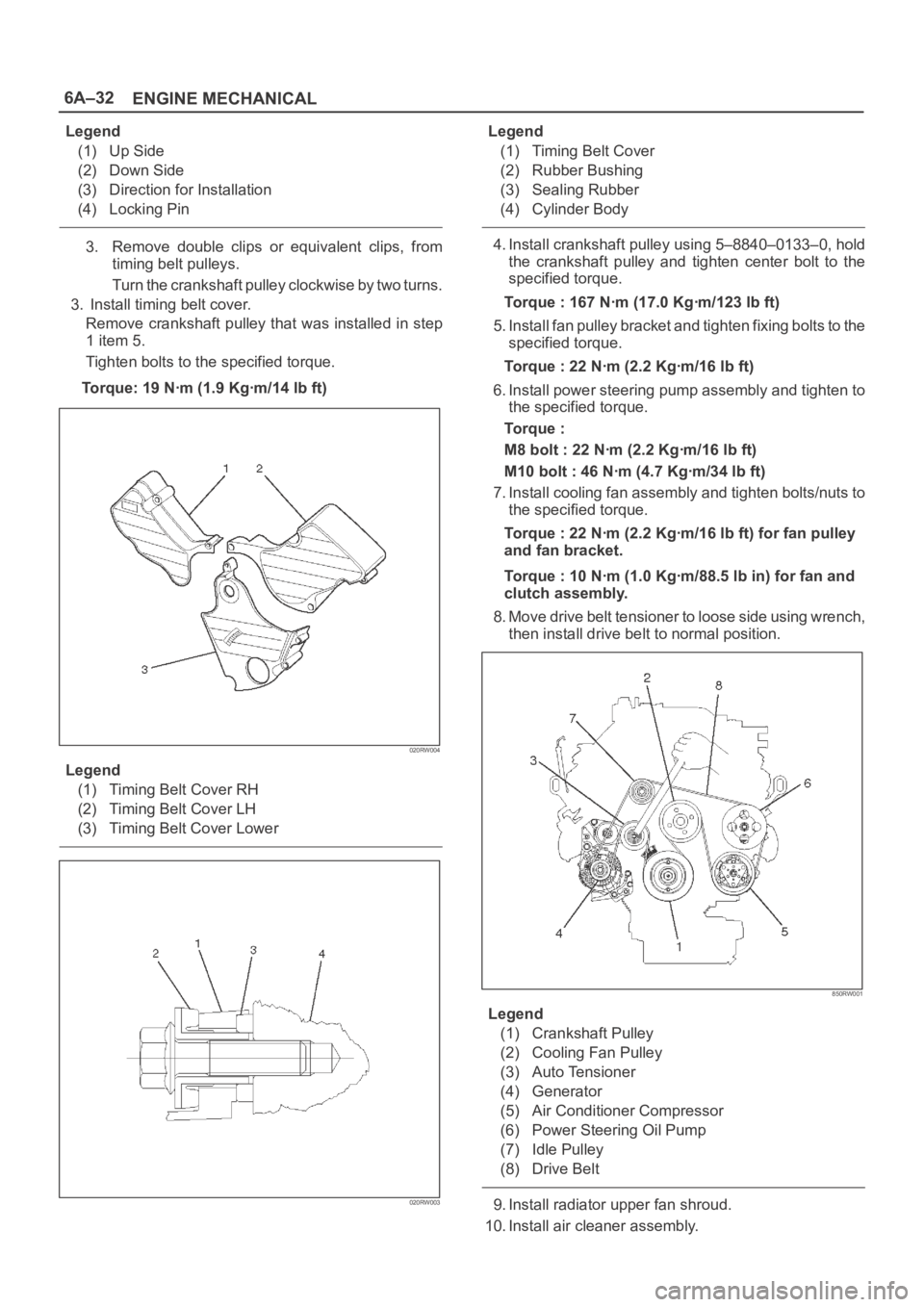
850RW001
Legend
(1) Crankshaft Pulley
(2) Cooling Fan Pulley
(3) Tensioner
(4) Generator
(5) Air Conditioner Compressor
(6) Power Steering Oil Pump
(7) Serpentine Belt
5. Remove cooling fan assembly four fixing nuts, then
the cooling fan assembly.
6. Remove crankshaft pulley assembly using J-8614-01
crankshaft holder, hold crankshaft pulley then
remove center bolt and pulley.
Installation
1. Install crankshaft pulley using J-8614-01 crankshaft
holder, hold the crankshaft pulley and tighten center
bolt to the specified torque.
Torque : 167 Nꞏm (17.0 Kgꞏm/123 lb ft)
2. Install cooling fan assembly and tighten bolts/nuts to
the specified torque.
Torque : 22 Nꞏm (2.2 Kgꞏm/16 lb ft) for fan pulley
and fan bracket.
Torque : 10 Nꞏm (1.0 Kgꞏm/88.5 lb in) for fan and
clutch assembly.
3. Move serpentine belt tensioner to loose side using
wrench, then install serpentine belt to normal
position.
4. Install radiator upper fan shroud.
5. Install air cleaner assembly.
Page 4528 of 6000
6A–32
ENGINE MECHANICAL
Legend
(1) Up Side
(2) Down Side
(3) Direction for Installation
(4) Locking Pin
3. Remove double clips or equivalent clips, from
timing belt pulleys.
Turn the crankshaft pulley clockwise by two turns.
3. Install timing belt cover.
Remove crankshaft pulley that was installed in step
1 item 5.
Tighten bolts to the specified torque.
Torque: 19 Nꞏm (1.9 Kgꞏm/14 lb ft)
020RW004
Legend
(1) Timing Belt Cover RH
(2) Timing Belt Cover LH
(3) Timing Belt Cover Lower
020RW003
Legend
(1) Timing Belt Cover
(2) Rubber Bushing
(3) Sealing Rubber
(4) Cylinder Body
4. Install crankshaft pulley using 5–8840–0133–0, hold
the crankshaft pulley and tighten center bolt to the
specified torque.
Torque : 167 Nꞏm (17.0 Kgꞏm/123 lb ft)
5. Install fan pulley bracket and tighten fixing bolts to the
specified torque.
Torque : 22 Nꞏm (2.2 Kgꞏm/16 lb ft)
6. Install power steering pump assembly and tighten to
the specified torque.
To r q u e :
M8 bolt : 22 Nꞏm (2.2 Kgꞏm/16 lb ft)
M10 bolt : 46 Nꞏm (4.7 Kgꞏm/34 lb ft)
7. Install cooling fan assembly and tighten bolts/nuts to
the specified torque.
Torque : 22 Nꞏm (2.2 Kgꞏm/16 lb ft) for fan pulley
and fan bracket.
Torque : 10 Nꞏm (1.0 Kgꞏm/88.5 lb in) for fan and
clutch assembly.
8. Move drive belt tensioner to loose side using wrench,
then install drive belt to normal position.
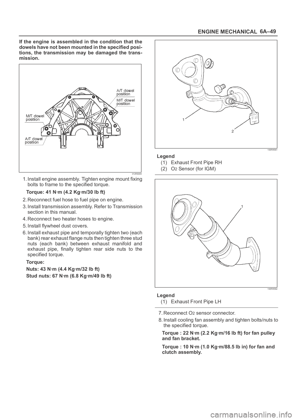
850RW001
Legend
(1) Crankshaft Pulley
(2) Cooling Fan Pulley
(3) Auto Tensioner
(4) Generator
(5) Air Conditioner Compressor
(6) Power Steering Oil Pump
(7) Idle Pulley
(8) Drive Belt
9. Install radiator upper fan shroud.
10. Install air cleaner assembly.
Page 4545 of 6000
6A–49
ENGINE MECHANICAL
If the engine is assembled in the condition that the
dowels have not been mounted in the specified posi-
tions, the transmission may be damaged the trans-
mission.
012RS009
1. Install engine assembly. Tighten engine mount fixing
bolts to frame to the specified torque.
Torque: 41 Nꞏm (4.2 Kgꞏm/30 lb ft)
2. Reconnect fuel hose to fuel pipe on engine.
3. Install transmission assembly. Refer to Transmission
section in this manual.
4. Reconnect two heater hoses to engine.
5. Install flywheel dust covers.
6. Install exhaust pipe and temporally tighten two (each
bank) rear exhaust flange nuts then tighten three stud
nuts (each bank) between exhaust manifold and
exhaust pipe, finally tighten rear side nuts to the
specified torque.
Torque:
Nuts: 43 Nꞏm (4.4 Kgꞏm/32 lb ft)
Stud nuts: 67 Nꞏm (6.8 Kgꞏm/49 lb ft)
150RW061
Legend
(1) Exhaust Front Pipe RH
(2) O
2 Sensor (for IGM)
150RW062
Legend
(1) Exhaust Front Pipe LH
7. Reconnect O2 sensor connector.
8. Install cooling fan assembly and tighten bolts/nuts to
the specified torque.
Torque : 22 Nꞏm (2.2 Kgꞏm/16 lb ft) for fan pulley
and fan bracket.
Torque : 10 Nꞏm (1.0 Kgꞏm/88.5 lb in) for fan and
clutch assembly.
Page 4605 of 6000
6B–12
ENGINE COOLING
Drive Belt and Cooling Fan
Drive Belt and Associated Parts
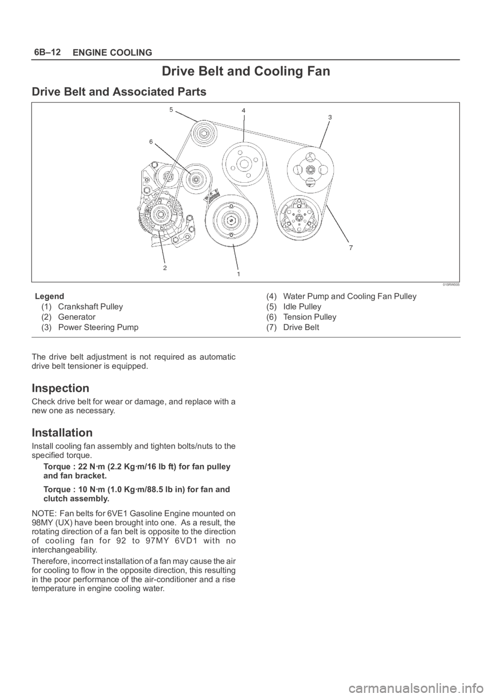
015RW005
Legend
(1) Crankshaft Pulley
(2) Generator
(3) Power Steering Pump(4) Water Pump and Cooling Fan Pulley
(5) Idle Pulley
(6) Tension Pulley
(7) Drive Belt
The drive belt adjustment is not required as automatic
drive belt tensioner is equipped.
Inspection
Check drive belt for wear or damage, and replace with a
new one as necessary.
Installation
Install cooling fan assembly and tighten bolts/nuts to the
specified torque.
Torque : 22 Nꞏm (2.2 Kgꞏm/16 lb ft) for fan pulley
and fan bracket.
Torque : 10 Nꞏm (1.0 Kgꞏm/88.5 lb in) for fan and
clutch assembly.
NOTE: Fan belts for 6VE1 Gasoline Engine mounted on
98MY (UX) have been brought into one. As a result, the
rotating direction of a fan belt is opposite to the direction
o f c o o l i n g f a n f o r 9 2 t o 9 7 M Y 6 V D 1 w i t h n o
interchangeability.
Therefore, incorrect installation of a fan may cause the air
for cooling to flow in the opposite direction, this resulting
in the poor performance of the air-conditioner and a rise
temperature in engine cooling water.
Page 4659 of 6000
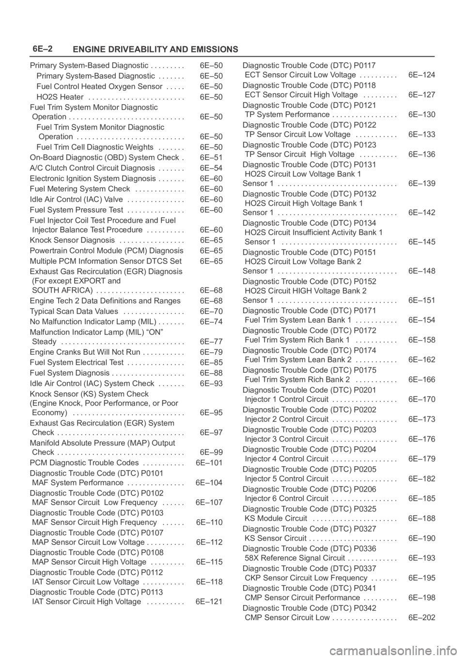
6E–2
ENGINE DRIVEABILITY AND EMISSIONS
Primary System-Based Diagnostic 6E–50. . . . . . . . .
Primary System-Based Diagnostic 6E–50. . . . . . .
Fuel Control Heated Oxygen Sensor 6E–50. . . . .
HO2S Heater 6E–50. . . . . . . . . . . . . . . . . . . . . . . . .
Fuel Trim System Monitor Diagnostic
Operation 6E–50. . . . . . . . . . . . . . . . . . . . . . . . . . . . . .
Fuel Trim System Monitor Diagnostic
Operation 6E–50. . . . . . . . . . . . . . . . . . . . . . . . . . . .
Fuel Trim Cell Diagnostic Weights 6E–50. . . . . . .
On-Board Diagnostic (OBD) System Check 6E–51.
A/C Clutch Control Circuit Diagnosis 6E–54. . . . . . .
Electronic Ignition System Diagnosis 6E–60. . . . . . .
Fuel Metering System Check 6E–60. . . . . . . . . . . . .
Idle Air Control (IAC) Valve 6E–60. . . . . . . . . . . . . . .
Fuel System Pressure Test 6E–60. . . . . . . . . . . . . . .
Fuel Injector Coil Test Procedure and Fuel
Injector Balance Test Procedure 6E–60. . . . . . . . . .
Knock Sensor Diagnosis 6E–65. . . . . . . . . . . . . . . . .
Powertrain Control Module (PCM) Diagnosis 6E–65
Multiple PCM Information Sensor DTCS Set 6E–65
Exhaust Gas Recirculation (EGR) Diagnosis
(For except EXPORT and
SOUTH AFRICA) 6E–68. . . . . . . . . . . . . . . . . . . . . . .
Engine Tech 2 Data Definitions and Ranges 6E–68
Typical Scan Data Values 6E–70. . . . . . . . . . . . . . . .
No Malfunction Indicator Lamp (MIL) 6E–74. . . . . . .
Malfunction Indicator Lamp (MIL) “ON”
Steady 6E–77. . . . . . . . . . . . . . . . . . . . . . . . . . . . . . . .
Engine Cranks But Will Not Run 6E–79. . . . . . . . . . .
Fuel System Electrical Test 6E–85. . . . . . . . . . . . . . .
Fuel System Diagnosis 6E–88. . . . . . . . . . . . . . . . . . .
Idle Air Control (IAC) System Check 6E–93. . . . . . .
Knock Sensor (KS) System Check
(Engine Knock, Poor Performance, or Poor
Economy) 6E–95. . . . . . . . . . . . . . . . . . . . . . . . . . . . .
Exhaust Gas Recirculation (EGR) System
Check 6E–97. . . . . . . . . . . . . . . . . . . . . . . . . . . . . . . . .
Manifold Absolute Pressure (MAP) Output
Check 6E–99. . . . . . . . . . . . . . . . . . . . . . . . . . . . . . . . .
PCM Diagnostic Trouble Codes 6E–101. . . . . . . . . . .
Diagnostic Trouble Code (DTC) P0101
MAF System Performance 6E–104. . . . . . . . . . . . . . .
Diagnostic Trouble Code (DTC) P0102
MAF Sensor Circuit Low Frequency 6E–107. . . . . .
Diagnostic Trouble Code (DTC) P0103
MAF Sensor Circuit High Frequency 6E–110. . . . . .
Diagnostic Trouble Code (DTC) P0107
MAP Sensor Circuit Low Voltage 6E–112. . . . . . . . . .
Diagnostic Trouble Code (DTC) P0108
MAP Sensor Circuit High Voltage 6E–115. . . . . . . . .
Diagnostic Trouble Code (DTC) P0112
IAT Sensor Circuit Low Voltage 6E–118. . . . . . . . . . .
Diagnostic Trouble Code (DTC) P0113
IAT Sensor Circuit High Voltage 6E–121. . . . . . . . . . Diagnostic Trouble Code (DTC) P0117
ECT Sensor Circuit Low Voltage 6E–124. . . . . . . . . .
Diagnostic Trouble Code (DTC) P0118
ECT Sensor Circuit High Voltage 6E–127. . . . . . . . .
Diagnostic Trouble Code (DTC) P0121
TP System Performance 6E–130. . . . . . . . . . . . . . . . .
Diagnostic Trouble Code (DTC) P0122
TP Sensor Circuit Low Voltage 6E–133. . . . . . . . . . .
Diagnostic Trouble Code (DTC) P0123
TP Sensor Circuit High Voltage 6E–136. . . . . . . . . .
Diagnostic Trouble Code (DTC) P0131
HO2S Circuit Low Voltage Bank 1
Sensor 1 6E–139. . . . . . . . . . . . . . . . . . . . . . . . . . . . . . .
Diagnostic Trouble Code (DTC) P0132
HO2S Circuit High Voltage Bank 1
Sensor 1 6E–142. . . . . . . . . . . . . . . . . . . . . . . . . . . . . . .
Diagnostic Trouble Code (DTC) P0134
HO2S Circuit Insufficient Activity Bank 1
Sensor 1 6E–145. . . . . . . . . . . . . . . . . . . . . . . . . . . . . .
Diagnostic Trouble Code (DTC) P0151
HO2S Circuit Low Voltage Bank 2
Sensor 1 6E–148. . . . . . . . . . . . . . . . . . . . . . . . . . . . . . .
Diagnostic Trouble Code (DTC) P0152
HO2S Circuit HIGH Voltage Bank 2
Sensor 1 6E–151. . . . . . . . . . . . . . . . . . . . . . . . . . . . . . .
Diagnostic Trouble Code (DTC) P0171
Fuel Trim System Lean Bank 1 6E–154. . . . . . . . . . .
Diagnostic Trouble Code (DTC) P0172
Fuel Trim System Rich Bank 1 6E–158. . . . . . . . . . .
Diagnostic Trouble Code (DTC) P0174
Fuel Trim System Lean Bank 2 6E–162. . . . . . . . . . .
Diagnostic Trouble Code (DTC) P0175
Fuel Trim System Rich Bank 2 6E–166. . . . . . . . . . .
Diagnostic Trouble Code (DTC) P0201
Injector 1 Control Circuit 6E–170. . . . . . . . . . . . . . . . .
Diagnostic Trouble Code (DTC) P0202
Injector 2 Control Circuit 6E–173. . . . . . . . . . . . . . . . .
Diagnostic Trouble Code (DTC) P0203
Injector 3 Control Circuit 6E–176. . . . . . . . . . . . . . . . .
Diagnostic Trouble Code (DTC) P0204
Injector 4 Control Circuit 6E–179. . . . . . . . . . . . . . . . .
Diagnostic Trouble Code (DTC) P0205
Injector 5 Control Circuit 6E–182. . . . . . . . . . . . . . . . .
Diagnostic Trouble Code (DTC) P0206
Injector 6 Control Circuit 6E–185. . . . . . . . . . . . . . . . .
Diagnostic Trouble Code (DTC) P0325
KS Module Circuit 6E–188. . . . . . . . . . . . . . . . . . . . . .
Diagnostic Trouble Code (DTC) P0327
KS Sensor Circuit 6E–190. . . . . . . . . . . . . . . . . . . . . . .
Diagnostic Trouble Code (DTC) P0336
58X Reference Signal Circuit 6E–193. . . . . . . . . . . . .
Diagnostic Trouble Code (DTC) P0337
CKP Sensor Circuit Low Frequency 6E–195. . . . . . .
Diagnostic Trouble Code (DTC) P0341
CMP Sensor Circuit Performance 6E–198. . . . . . . . .
Diagnostic Trouble Code (DTC) P0342
CMP Sensor Circuit Low 6E–202. . . . . . . . . . . . . . . . .
Page 4661 of 6000
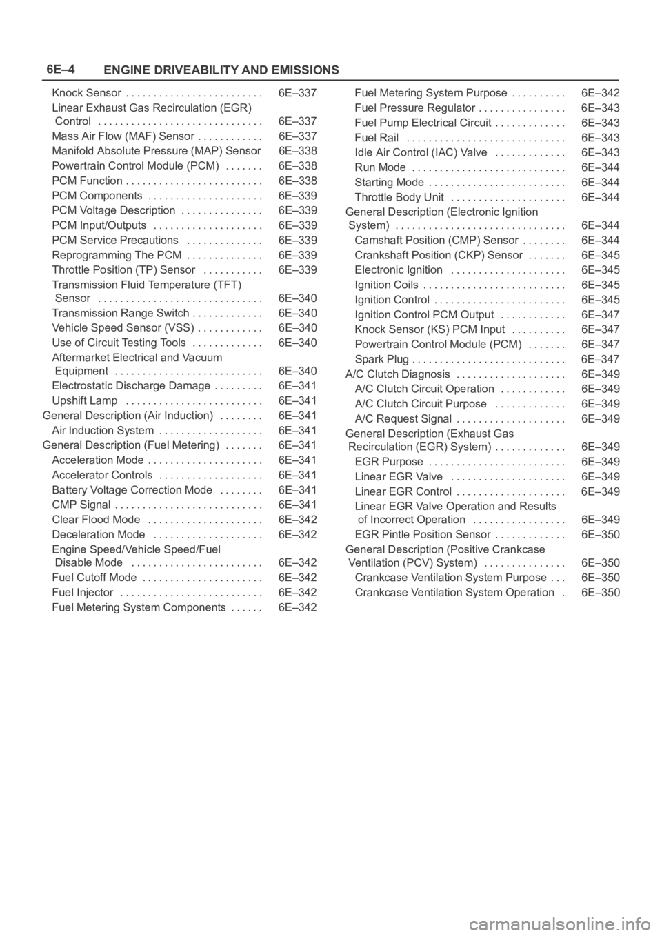
6E–4
ENGINE DRIVEABILITY AND EMISSIONS
Knock Sensor 6E–337. . . . . . . . . . . . . . . . . . . . . . . . .
Linear Exhaust Gas Recirculation (EGR)
Control 6E–337. . . . . . . . . . . . . . . . . . . . . . . . . . . . . .
Mass Air Flow (MAF) Sensor 6E–337. . . . . . . . . . . .
Manifold Absolute Pressure (MAP) Sensor 6E–338
Powertrain Control Module (PCM) 6E–338. . . . . . .
PCM Function 6E–338. . . . . . . . . . . . . . . . . . . . . . . . .
PCM Components 6E–339. . . . . . . . . . . . . . . . . . . . .
PCM Voltage Description 6E–339. . . . . . . . . . . . . . .
PCM Input/Outputs 6E–339. . . . . . . . . . . . . . . . . . . .
PCM Service Precautions 6E–339. . . . . . . . . . . . . .
Reprogramming The PCM 6E–339. . . . . . . . . . . . . .
Throttle Position (TP) Sensor 6E–339. . . . . . . . . . .
Transmission Fluid Temperature (TFT)
Sensor 6E–340. . . . . . . . . . . . . . . . . . . . . . . . . . . . . .
Transmission Range Switch 6E–340. . . . . . . . . . . . .
Vehicle Speed Sensor (VSS) 6E–340. . . . . . . . . . . .
Use of Circuit Testing Tools 6E–340. . . . . . . . . . . . .
Aftermarket Electrical and Vacuum
Equipment 6E–340. . . . . . . . . . . . . . . . . . . . . . . . . . .
Electrostatic Discharge Damage 6E–341. . . . . . . . .
Upshift Lamp 6E–341. . . . . . . . . . . . . . . . . . . . . . . . .
General Description (Air Induction) 6E–341. . . . . . . .
Air Induction System 6E–341. . . . . . . . . . . . . . . . . . .
General Description (Fuel Metering) 6E–341. . . . . . .
Acceleration Mode 6E–341. . . . . . . . . . . . . . . . . . . . .
Accelerator Controls 6E–341. . . . . . . . . . . . . . . . . . .
Battery Voltage Correction Mode 6E–341. . . . . . . .
CMP Signal 6E–341. . . . . . . . . . . . . . . . . . . . . . . . . . .
Clear Flood Mode 6E–342. . . . . . . . . . . . . . . . . . . . .
Deceleration Mode 6E–342. . . . . . . . . . . . . . . . . . . .
Engine Speed/Vehicle Speed/Fuel
Disable Mode 6E–342. . . . . . . . . . . . . . . . . . . . . . . .
Fuel Cutoff Mode 6E–342. . . . . . . . . . . . . . . . . . . . . .
Fuel Injector 6E–342. . . . . . . . . . . . . . . . . . . . . . . . . .
Fuel Metering System Components 6E–342. . . . . . Fuel Metering System Purpose 6E–342. . . . . . . . . .
Fuel Pressure Regulator 6E–343. . . . . . . . . . . . . . . .
Fuel Pump Electrical Circuit 6E–343. . . . . . . . . . . . .
Fuel Rail 6E–343. . . . . . . . . . . . . . . . . . . . . . . . . . . . .
Idle Air Control (IAC) Valve 6E–343. . . . . . . . . . . . .
Run Mode 6E–344. . . . . . . . . . . . . . . . . . . . . . . . . . . .
Starting Mode 6E–344. . . . . . . . . . . . . . . . . . . . . . . . .
Throttle Body Unit 6E–344. . . . . . . . . . . . . . . . . . . . .
General Description (Electronic Ignition
System) 6E–344. . . . . . . . . . . . . . . . . . . . . . . . . . . . . . .
Camshaft Position (CMP) Sensor 6E–344. . . . . . . .
Crankshaft Position (CKP) Sensor 6E–345. . . . . . .
Electronic Ignition 6E–345. . . . . . . . . . . . . . . . . . . . .
Ignition Coils 6E–345. . . . . . . . . . . . . . . . . . . . . . . . . .
Ignition Control 6E–345. . . . . . . . . . . . . . . . . . . . . . . .
Ignition Control PCM Output 6E–347. . . . . . . . . . . .
Knock Sensor (KS) PCM Input 6E–347
. . . . . . . . . .
Powertrain Control Module (PCM) 6E–347. . . . . . .
Spark Plug 6E–347. . . . . . . . . . . . . . . . . . . . . . . . . . . .
A/C Clutch Diagnosis 6E–349. . . . . . . . . . . . . . . . . . . .
A/C Clutch Circuit Operation 6E–349. . . . . . . . . . . .
A/C Clutch Circuit Purpose 6E–349. . . . . . . . . . . . .
A/C Request Signal 6E–349. . . . . . . . . . . . . . . . . . . .
General Description (Exhaust Gas
Recirculation (EGR) System) 6E–349. . . . . . . . . . . . .
EGR Purpose 6E–349. . . . . . . . . . . . . . . . . . . . . . . . .
Linear EGR Valve 6E–349. . . . . . . . . . . . . . . . . . . . .
Linear EGR Control 6E–349. . . . . . . . . . . . . . . . . . . .
Linear EGR Valve Operation and Results
of Incorrect Operation 6E–349. . . . . . . . . . . . . . . . .
EGR Pintle Position Sensor 6E–350. . . . . . . . . . . . .
General Description (Positive Crankcase
Ventilation (PCV) System) 6E–350. . . . . . . . . . . . . . .
Crankcase Ventilation System Purpose 6E–350. . .
Crankcase Ventilation System Operation 6E–350.
Page 4676 of 6000
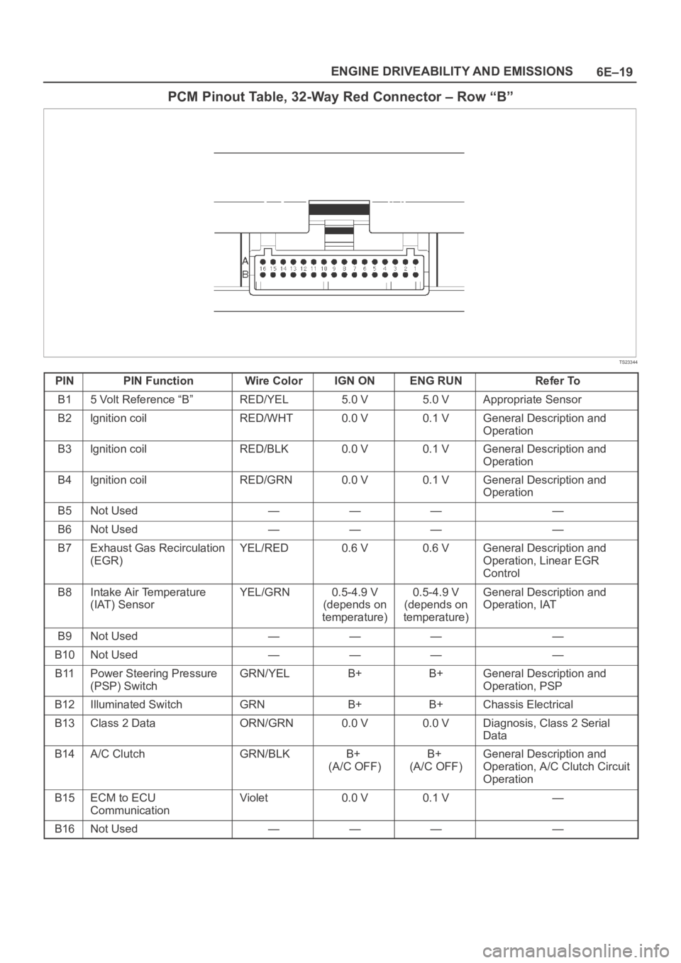
6E–19 ENGINE DRIVEABILITY AND EMISSIONS
PCM Pinout Table, 32-Way Red Connector – Row “B”
TS23344
PINPIN FunctionWire ColorIGN ONENG RUNRefer To
B15 Volt Reference “B”RED/YEL5.0 V5.0 VAppropriate Sensor
B2lgnition coilRED/WHT0.0 V0.1 VGeneral Description and
Operation
B3lgnition coilRED/BLK0.0 V0.1 VGeneral Description and
Operation
B4lgnition coilRED/GRN0.0 V0.1 VGeneral Description and
Operation
B5Not Used————
B6Not Used————
B7Exhaust Gas Recirculation
(EGR)YEL/RED0.6 V0.6 VGeneral Description and
Operation, Linear EGR
Control
B8Intake Air Temperature
(IAT) SensorYEL/GRN0.5-4.9 V
(depends on
temperature)0.5-4.9 V
(depends on
temperature)General Description and
Operation, IAT
B9Not Used————
B10Not Used————
B11Power Steering Pressure
(PSP) SwitchGRN/YELB+B+General Description and
Operation, PSP
B12Illuminated SwitchGRNB+B+Chassis Electrical
B13Class 2 DataORN/GRN0.0 V0.0 VDiagnosis, Class 2 Serial
Data
B14A/C ClutchGRN/BLKB+
(A/C OFF)B+
(A/C OFF)General Description and
Operation, A/C Clutch Circuit
Operation
B15ECM to ECU
CommunicationViolet0.0 V0.1 V—
B16Not Used————
Page 4679 of 6000
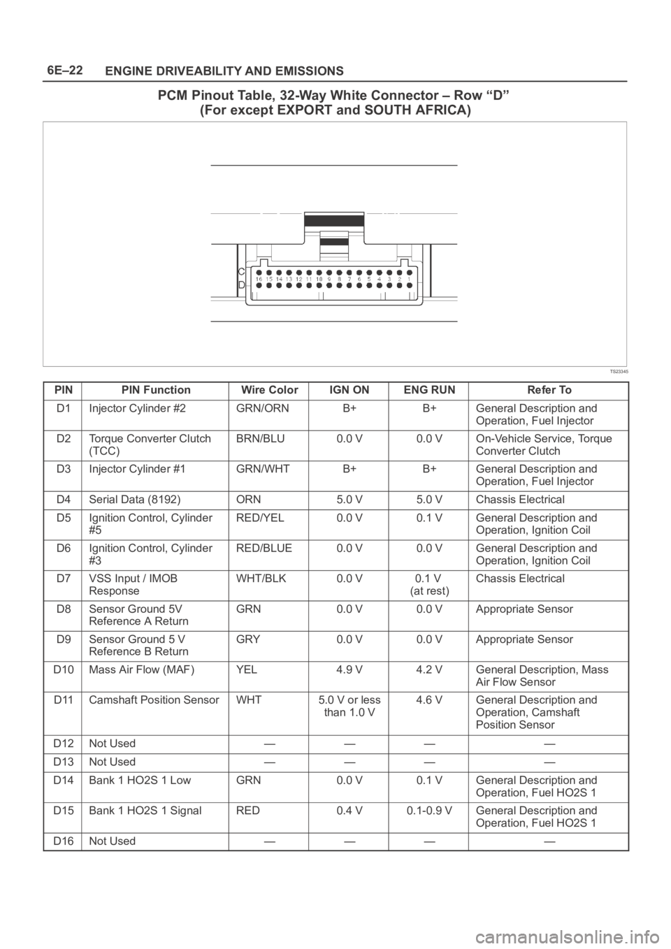
6E–22
ENGINE DRIVEABILITY AND EMISSIONS
PCM Pinout Table, 32-Way White Connector – Row “D”
(For except EXPORT and SOUTH AFRICA)
TS23345
PINPIN FunctionWire ColorIGN ONENG RUNRefer To
D1Injector Cylinder #2GRN/ORNB+B+General Description and
Operation, Fuel Injector
D2Torque Converter Clutch
(TCC)BRN/BLU0.0 V0.0 VOn-Vehicle Service, Torque
Converter Clutch
D3Injector Cylinder #1GRN/WHTB+B+General Description and
Operation, Fuel Injector
D4Serial Data (8192)ORN5.0 V5.0 VChassis Electrical
D5Ignition Control, Cylinder
#5RED/YEL0.0 V0.1 VGeneral Description and
Operation, Ignition Coil
D6Ignition Control, Cylinder
#3RED/BLUE0.0 V0.0 VGeneral Description and
Operation, Ignition Coil
D7VSS Input / IMOB
ResponseWHT/BLK0.0 V0.1 V
(at rest)Chassis Electrical
D8Sensor Ground 5V
Reference A ReturnGRN0.0 V0.0 VAppropriate Sensor
D9Sensor Ground 5 V
Reference B ReturnGRY0.0 V0.0 VAppropriate Sensor
D10Mass Air Flow (MAF)YEL4.9 V4.2 VGeneral Description, Mass
Air Flow Sensor
D11Camshaft Position SensorWHT5.0 V or less
than 1.0 V4.6 VGeneral Description and
Operation, Camshaft
Position Sensor
D12Not Used————
D13Not Used————
D14Bank 1 HO2S 1 LowGRN0.0 V0.1 VGeneral Description and
Operation, Fuel HO2S 1
D15Bank 1 HO2S 1 SignalRED0.4 V0.1-0.9 VGeneral Description and
Operation, Fuel HO2S 1
D16Not Used————