Page 4296 of 6000
TRANSFER CASE (STANDARD TYPE)
4D1–35
Limit : 3.0 mm (0.118 in)
226RS037
2WD–4WD 3–Cone Synchronizer (Shift On
The Fly model)
1. Use a thickness gauge to measure the clearance
between the block ring and the dog teeth.
2. If the measured value exceeds the specified limit, the
2WD–4WD synchronizer assembly must be
replaced.
Block ring and insert clearance
Standard : 1.5 mm (0.059 in)
Limit : 0.8 mm (0.031 in)
226RW142
Clutch Hub and Insert Clearance
1. Use a thickness gauge to measure the clearance
between the clutch hub and the insert.
2. If the measured value exceeds the specified limit, the
clutch hub and the insert must be replaced.
Clutch hub and insert clearance
Standard : 0.01–0.19 mm (0.0004–0.0075 in)
Limit : 0.3 mm (0.012 in)
226RS038
Detent Springs
1. Inspect the springs for distortion, cracks or wear.
Replace if these conditions are present.
Detent Spring Free Length
1. Use a vernier caliper to measure the detent spring
free length.
Page 4300 of 6000

TRANSFER CASE (STANDARD TYPE)
4D1–39
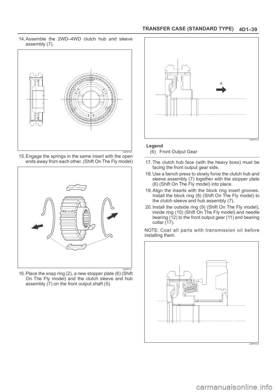
14. Assemble the 2WD–4WD clutch hub and sleeve
assembly (7).
226RW140
15. Engage the springs in the same insert with the open
ends away from each other. (Shift On The Fly model)
226RW141
16. Place the snap ring (2), a new stopper plate (6) (Shift
On The Fly model) and the clutch sleeve and hub
assembly (7) on the front output shaft (5).
226RW135
Legend
(6) Front Output Gear
17. The clutch hub face (with the heavy boss) must be
facing the front output gear side.
18. Use a bench press to slowly force the clutch hub and
sleeve assembly (7) together with the stopper plate
(6) (Shift On The Fly model) into place.
19. Align the inserts with the block ring insert grooves.
Install the block ring (8) (Shift On The Fly model) to
the clutch sleeve and hub assembly (7).
20. Install the outside ring (9) (Shift On The Fly model),
inside ring (10) (Shift On The Fly model) and needle
bearing (12) to the front output gear (11) and bearing
collar (17).
NOTE: Coat all parts with transmission oil before
installing them.
226RW139
Page 4302 of 6000

TRANSFER CASE (STANDARD TYPE)
4D1–41
27. Use a pair of snap ring pliers to install the snap ring
(19) to the output shaft (5).
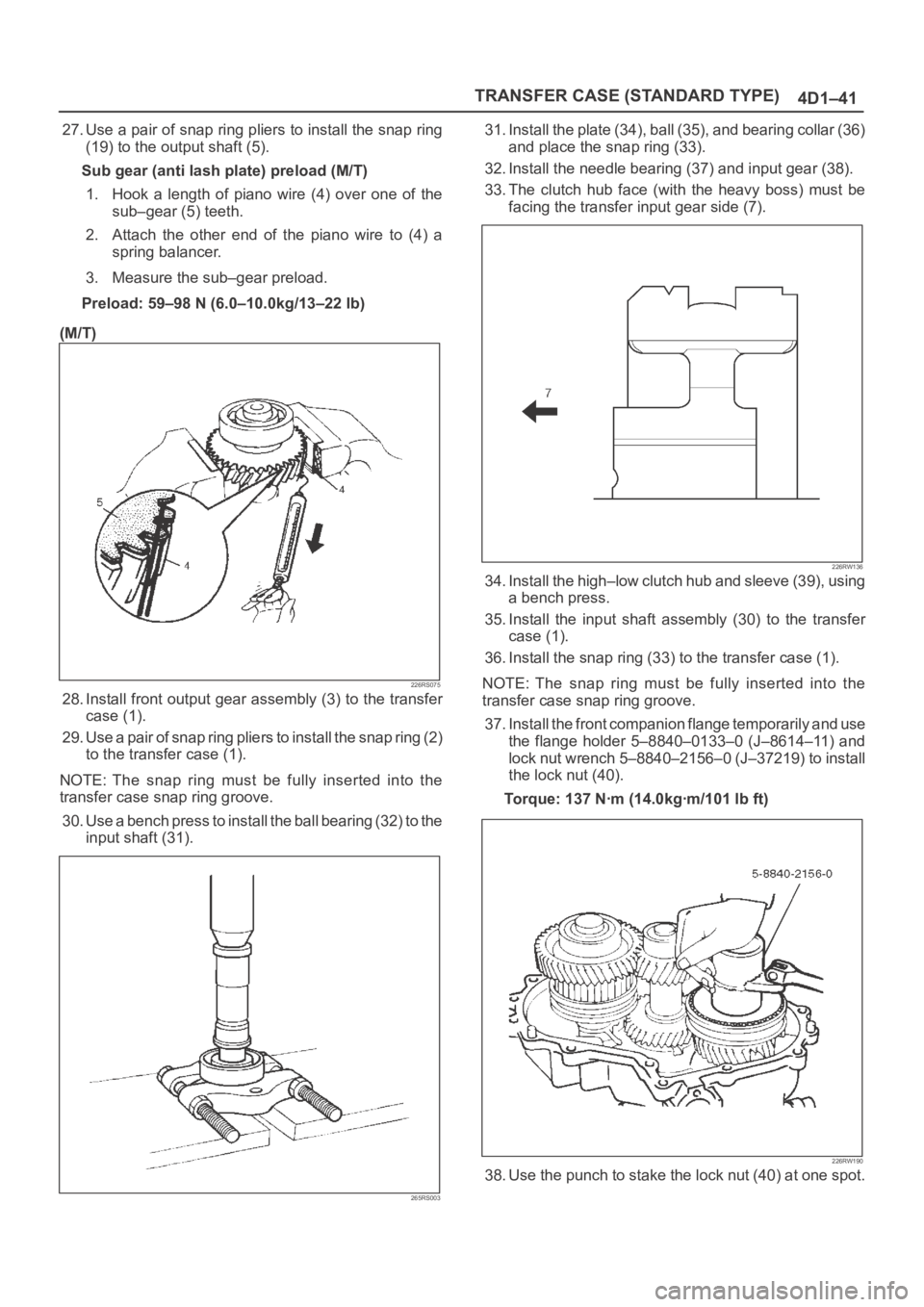
Sub gear (anti lash plate) preload (M/T)
1. Hook a length of piano wire (4) over one of the
sub–gear (5) teeth.
2. Attach the other end of the piano wire to (4) a
spring balancer.
3. Measure the sub–gear preload.
Preload: 59–98 N (6.0–10.0kg/13–22 lb)
(M/T)
226RS075
28. Install front output gear assembly (3) to the transfer
case (1).
29. Use a pair of snap ring pliers to install the snap ring (2)
to the transfer case (1).
NOTE: The snap ring must be fully inserted into the
transfer case snap ring groove.
30. Use a bench press to install the ball bearing (32) to the
input shaft (31).
265RS003
31. Install the plate (34), ball (35), and bearing collar (36)
and place the snap ring (33).
32. Install the needle bearing (37) and input gear (38).
33. The clutch hub face (with the heavy boss) must be
facing the transfer input gear side (7).
226RW136
34. Install the high–low clutch hub and sleeve (39), using
a bench press.
35. Install the input shaft assembly (30) to the transfer
case (1).
36. Install the snap ring (33) to the transfer case (1).
NOTE: The snap ring must be fully inserted into the
transfer case snap ring groove.
37. Install the front companion flange temporarily and use
the flange holder 5–8840–0133–0 (J–8614–11) and
lock nut wrench 5–8840–2156–0 (J–37219) to install
the lock nut (40).
Torque: 137 Nꞏm (14.0kgꞏm/101 lb ft)
226RW190
38. Use the punch to stake the lock nut (40) at one spot.
Page 4308 of 6000

4D2–1 TRANSFER CASE (TOD)
DRIVELINE/AXLE
TRANSFER CASE (TOD)
CONTENTS
Service Precaution 4D2–1. . . . . . . . . . . . . . . . . . . . . .
Transfer Case Assembly 4D2–2. . . . . . . . . . . . . . . . .
Removal 4D2–2. . . . . . . . . . . . . . . . . . . . . . . . . . . . .
Installation 4D2–3. . . . . . . . . . . . . . . . . . . . . . . . . . . .
Transfer Rear Oil Seal 4D2–5. . . . . . . . . . . . . . . . . . .
Transfer Rear Oil Seal and Associated
Parts 4D2–5. . . . . . . . . . . . . . . . . . . . . . . . . . . . . . . .
Removal 4D2–5. . . . . . . . . . . . . . . . . . . . . . . . . . . . .
Installation 4D2–5. . . . . . . . . . . . . . . . . . . . . . . . . . . .
TOD ECU 4D2–7. . . . . . . . . . . . . . . . . . . . . . . . . . . . . .
Removal 4D2–7. . . . . . . . . . . . . . . . . . . . . . . . . . . . .
Installation 4D2–7. . . . . . . . . . . . . . . . . . . . . . . . . . . .
Unit Repair 4D2–8. . . . . . . . . . . . . . . . . . . . . . . . . . . . .
Inspection 4D2–8. . . . . . . . . . . . . . . . . . . . . . . . . . . .
Transfer Case 4D2–9. . . . . . . . . . . . . . . . . . . . . . . . . .
Disassembled View 4D2–9. . . . . . . . . . . . . . . . . . . .
Disassembly 4D2–9. . . . . . . . . . . . . . . . . . . . . . . . . .
Reassembly 4D2–10. . . . . . . . . . . . . . . . . . . . . . . . . .
Transfer Cover Assembly 4D2–12. . . . . . . . . . . . . . . .
Disassembled View 4D2–12. . . . . . . . . . . . . . . . . . . .
Disassembly 4D2–12. . . . . . . . . . . . . . . . . . . . . . . . . .
Reassembly 4D2–14. . . . . . . . . . . . . . . . . . . . . . . . . .
Transfer Case Assembly Clutch Pack and
Clutch Cam 4D2–16. . . . . . . . . . . . . . . . . . . . . . . . . . . .
Disassembled View 4D2–16. . . . . . . . . . . . . . . . . . . . Disassembly 4D2–16. . . . . . . . . . . . . . . . . . . . . . . . . .
Sprocket and Mechanical Lock 4D2–18. . . . . . . . . . . .
Disassembled View 4D2–18. . . . . . . . . . . . . . . . . . . .
Disassembly 4D2–18. . . . . . . . . . . . . . . . . . . . . . . . . .
Output Shafts and Shift Control Shaft 4D2–20. . . . . .
Disassembled View 4D2–20. . . . . . . . . . . . . . . . . . . .
Disassembly 4D2–21. . . . . . . . . . . . . . . . . . . . . . . . . .
Transfer Case 4D2–23. . . . . . . . . . . . . . . . . . . . . . . . . .
Disassembled View 4D2–23. . . . . . . . . . . . . . . . . . . .
Disassembly 4D2–24. . . . . . . . . . . . . . . . . . . . . . . . . .
Inspection and Repair 4D2–26. . . . . . . . . . . . . . . . . .
Transfer Case 4D2–30. . . . . . . . . . . . . . . . . . . . . . . . . .
Disassembled View 4D2–30. . . . . . . . . . . . . . . . . . . .
Reassembly 4D2–30. . . . . . . . . . . . . . . . . . . . . . . . . .
Output Shafts and Shift Control Shaft 4D2–34. . . . . .
Disassembled View 4D2–34. . . . . . . . . . . . . . . . . . . .
Reassembly 4D2–34. . . . . . . . . . . . . . . . . . . . . . . . . .
Sprocket and Mechanical Lock 4D2–37. . . . . . . . . . . .
Disassembled View 4D2–37. . . . . . . . . . . . . . . . . . . .
Reassembly 4D2–37. . . . . . . . . . . . . . . . . . . . . . . . . .
Clutch Pack and Clutch Cam 4D2–39. . . . . . . . . . . . .
Disassembled View 4D2–39. . . . . . . . . . . . . . . . . . . .
Reassembly 4D2–39. . . . . . . . . . . . . . . . . . . . . . . . . .
Main Data and Specifications 4D2–41. . . . . . . . . . . . .
Special Tools 4D2–43. . . . . . . . . . . . . . . . . . . . . . . . . . .
Service Precaution
WARNING: IF SO EQUIPPED WITH A
SUPPLEMENTAL RESTRAINT SYSTEM (SRS),
REFER TO THE SRS COMPONENT AND WIRING
LOCATION VIEW IN ORDER TO DETERMINE
WHETHER YOU ARE PERFORMING SERVICE ON OR
NEAR THE SRS COMPONENTS OR THE SRS
WIRING. WHEN YOU ARE PERFORMING SERVICE
ON OR NEAR THE SRS COMPONENTS OR THE SRS
WIRING, REFER TO THE SRS SERVICE
INFORMATION. FAILURE TO FOLLOW WARNINGS
COULD RESULT IN POSSIBLE AIR BAG
DEPLOYMENT, PERSONAL INJURY, OR
OTHERWISE UNNEEDED SRS SYSTEM REPAIRS.CAUTION: Always use the correct fastener in the
proper location. When you replace a fastener, use
ONLY the exact part number for that application.
ISUZU will call out those fasteners that require a
replacement after removal. ISUZU will also call out
the fasteners that require thread lockers or thread
sealant. UNLESS OTHERWISE SPECIFIED, do not
use supplemental coatings (Paints, greases, or other
corrosion inhibitors) on threaded fasteners or
fastener joint interfaces. Generally, such coatings
adversely affect the fastener torque and the joint
clamping force, and may damage the fastener. When
you install fasteners, use the correct tightening
sequence and specifications. Following these
instructions can help you avoid damage to parts and
systems.
Page 4323 of 6000
4D2–16
TRANSFER CASE (TOD)
Transfer Case Assembly Clutch Pack and Clutch Cam
Disassembled View
266RW006
Legend
(1) Clutch Pack Assembly
(2) Insulator Washer
(3) Armature Plate
(4) Snap Ring(5) Wave Spring
(6) Cam Pulley
(7) Cam Ball
(8) Cam and Coil Housing
(9) Thrust Bearing
Disassembly
1. Remove the thrust bearing.
2. Remove the cam and coil housing.
NOTE: When the cam and coil housing is removed, the
cam balls may be detached together with the housing. Be
careful not to lose the ball.
3. Remove the cam ball.
266RW013
Page 4324 of 6000
4D2–17 TRANSFER CASE (TOD)
4. Remove the cam pulley.
5. Remove the wave spring.
6. Using snap ring pliers, remove the snap ring.
NOTE: Be careful not to damage the snap ring.
266RW009
7. Remove the armature plate.
8. Remove the insulator washer.
9. Remove the clutch pack assembly as a package.
266RW017
Page 4335 of 6000

4D2–28
TRANSFER CASE (TOD)
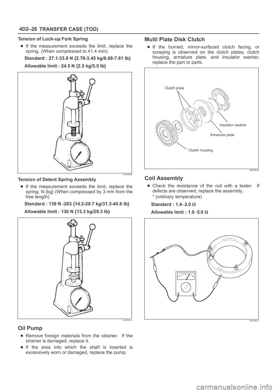
Tension of Lock-up Fork Spring
If the measurement exceeds the limit, replace the
spring. (When compressed to 41.4 mm)
Standard : 27.1-33.8 N {2.76-3.45 kg/6.08-7.61 Ib}
Allowable limit : 24.5 N {2.5 kg/5.5 Ib}
014RW048
Tension of Detent Spring Assembly
If the measurement exceeds the limit, replace the
spring. N {kg} (When compressed by 3 mm from the
free length)
Standard : 139 N -203 {14.2-20.7 kg/31.3-45.6 Ib}
Allowable limit : 130 N {13.3 kg/29.3 Ib}
261RW041
Oil Pump
Remove foreign materials from the strainer. If the
strainer is damaged, replace it.
If the area into which the shaft is inserted is
excessively worn or damaged, replace the pump.
Multi Plate Disk Clutch
If the burned, mirror-surfaced clutch facing, or
scraping is observed on the clutch plates, clutch
housing, armature plate, and insulator washer,
replace the part or parts.
266RW003
Coil Assembly
Check the resistance of the coil with a tester. If
defects are observed, replace the assembly.
* (ordinary temperature)
Standard : 1.4
2.0
Allowable limit : 1.05.0
261RW031
Page 4346 of 6000
4D2–39 TRANSFER CASE (TOD)
Clutch Pack and Clutch Cam
Disassembled View
266RW006
Legend
(1) Clutch Pack Assembly
(2) Insulator Washer
(3) Armature Plate
(4) Snap Ring(5) Wave Spring
(6) Cam Pulley
(7) Cam Ball
(8) Cam and Coil Housing
(9) Thrust Bearing
Reassembly
1. Mount the clutch pack assembly to which the multi
plate disk clutch is already installed to the output
shaft.
NOTE: Mount the clutch pack assembly while adjusting
the phase of both the clutch housing and drive sprocket.
2. Install the insulator washer.
3. Install the armature plate.