Page 3704 of 6000
FULL AUTO display
INTAKE indication
(LED)
(switching between
fresh and interior air)
MODE indication
(LED) (Blow port)
AC display (LED)
FAN indication (LED)
FAN KNOB
AUTO SET
REC FRESH SWITCH
TEMP LEVER
(temperature control)
MODE SWITCH
(blow port selection)
AC SWITCH
IN CAR SENSOR
AMBIENT SENSOR
SUN SENSOR
DUCT SENSOR
MIX ACTUATOR
POTENTIOMETER
MODE ACTUATOR
POTENTIOMETER
AIR MIX DOOR
MODE DOOR
INTAKE ACTUATOR
RECINTAKE DOOR
FAN MOTORPOWER
TRANSISTOR
AUTOMATIC HEATER/AIR CONDITIONER CONTROL UNIT (with the built-in micro-computer)
MAX HI RELAY
PRESSURE
SWITCHAIR CONDITIONER
THERMO RELAY
COMPRESSOR
SWITCH MAGNET
CLUTCH
PCM
PRESSURE
SWITCHAIR CONDITIONER
THERMO RELAYMAGNET
CLUTCH
(4JX1engine)
MIX FRESH
F01RY00009
Page 3747 of 6000
I-32
C-1C-3I-33
E-3E-19B-19C-25
A 2
B-361
H-14
C-19
25A
BLOWER
MOTOR
C-20
10A
A/C FL-1
80A
MAIN
Heater
Relay
1B-3610
H-13
0.3
B 0.85
W/G0.85
W/R
3.0
W
3.0
L/R
0.5
BR
1.25
B
B-19
BODY-LH3
B-36
4B-36
BATT.(+)
Blower
MotorIntake
Actuator STARTER
RELAY(1)
0.5
LG 0.5
BR0.5
BR
0.5
G/W
0.5
P/G0.5
P/G0.5
G/O
0.5
G/O
PCM
(C3-E15)
31 13
COMP-F/B 70.5
BR
0.5
BR/Y 0.3
G/B0.5
G/B0.5
BR/Y 0.5
BR
Triple
Pressure
Switch
0.5
BR
A
A/C
Thermo Relay
Auto A/C Control Unit
3X-5
16
H-1617H-16
14
I-3218I-33
1X-5
13H-24
12
H-41
2 1
C-25
C-25
4X-5X-5 2
X-57
H-16
A/C
Compressor
Relay
Magnetic
clutch
1X-7
3X-74X-72
X-7
PCM
(C-1-B14)
E-39
1
H-67
H-41
5
H-41
Engine
Coolant
Temperature
Sensor
ENGINE COOLANT
TEMPERATURE GAUGE
0.5
Y/B
0.5
Y/B
0.5
Y/B
E-1911
1
H-61
H-24
I-334
B-36X-5X-7
H-14H-16
H-24
H-13
H-6H-41
6H-41
D08RY00182
Page 3750 of 6000
C-25
0.5 BR
C-25
X-5X-5
X-5X-5
2 1
4 3
0.5 P/G FL-1 MAIN
80A
C-20
10A A/C
0.5 G/W 0.5 G/O
C-25E-27H-16
Pressure
switch
Relay:
Air conditioning
thermostat
Automatic heater/air conditioner
control unitRelay:
Air conditioning
0.5 BR
1
2
I-3214
Fan ON
I-32X-5
E-271
Magnet
clutch
B-36
B-36
H-1616
D08RY00183
Page 3768 of 6000
7. Install drive plate bolt by using drive plate holder
J-7624 (1) to prevent the drive plate from rotating.
Tighten the drive plate bolt to the specified torque.
Torque: 13 Nꞏm (113 lb in)
After tightening the drive plate bolt, check to be
sure the pulley rotates smoothly.
Check to be sure that the clutch clearance is
between 0.3-0.6 mm (0.01-0.02 in.)
If necessary, install adjusting shim(s).
Adjusting shims are available in the following
thickness.
Thickness
0.1 mm (0.0039 in.)
0.3 mm (0.0118 in.)
0.5 mm (0.0197 in.)
1
901RX055
871RX014
Page 3776 of 6000
19. Install shim(s).
20. Install drive plate.
Install the drive plate to the compressor drive
shaft together with the original shim(s)(1) press
the drive plate by hand.
21. Install drive plate bolt by using drive plate holder
J-7624 (1) to prevent the drive plate from rotating.
Tighten the bolt to the specified torque.
Torque: 15Nꞏm (11 lbꞏin)
NOTE
After tightening the bolt, check to be sure the
pulley rotates smoothly.
Check to be sure that the clutch clearance is
between 0.3–0.6 mm (0.01–0.02 in.)
If necessary, install adjusting shim(s).
Adjusting shims are available in the following
thickness.
Thickness
0.1 mm (0.0039 in.)
0.3 mm (0.0118 in.)
0.5 mm (0.0197 in.)
1
871RY00009
871RY00007
1
901RY00010
Page 3777 of 6000

HD6 TYPE COMPRESSOR
Metric Thread Size Information
Compressor to mounting bracket bolts (Front)
M10
1.5 – 6H
Compressor to mounting bracket bolts (Rear)
M8
1.25 – 6H
Suction-discharge port screw
M10
1.5 – 6HCompressor shaft
M9
1.25 – 6H
Internal hub-clutch drive assembly
M22
1.5 – 6H
COMPRESSOR CLUTCH PLATE AND HUB
ASSEMBLY
Removal
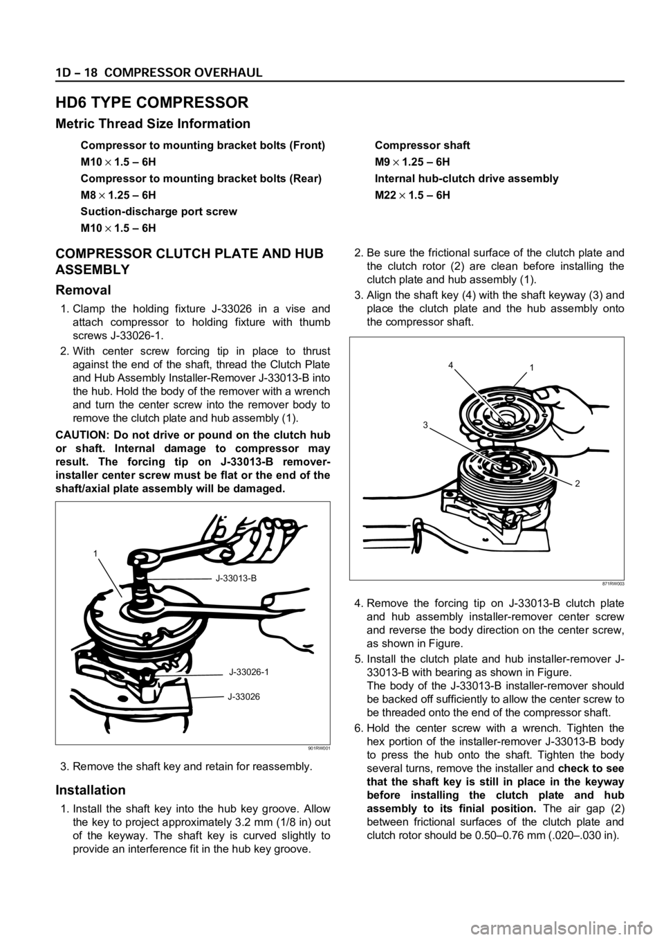
1. Clamp the holding fixture J-33026 in a vise and
attach compressor to holding fixture with thumb
screws J-33026-1.
2. With center screw forcing tip in place to thrust
against the end of the shaft, thread the Clutch Plate
and Hub Assembly Installer-Remover J-33013-B into
the hub. Hold the body of the remover with a wrench
and turn the center screw into the remover body to
remove the clutch plate and hub assembly (1).
CAUTION: Do not drive or pound on the clutch hub
or shaft. Internal damage to compressor may
result. The forcing tip on J-33013-B remover-
installer center screw must be flat or the end of the
shaft/axial plate assembly will be damaged.
3. Remove the shaft key and retain for reassembly.
Installation
1. Install the shaft key into the hub key groove. Allow
the key to project approximately 3.2 mm (1/8 in) out
of the keyway. The shaft key is curved slightly to
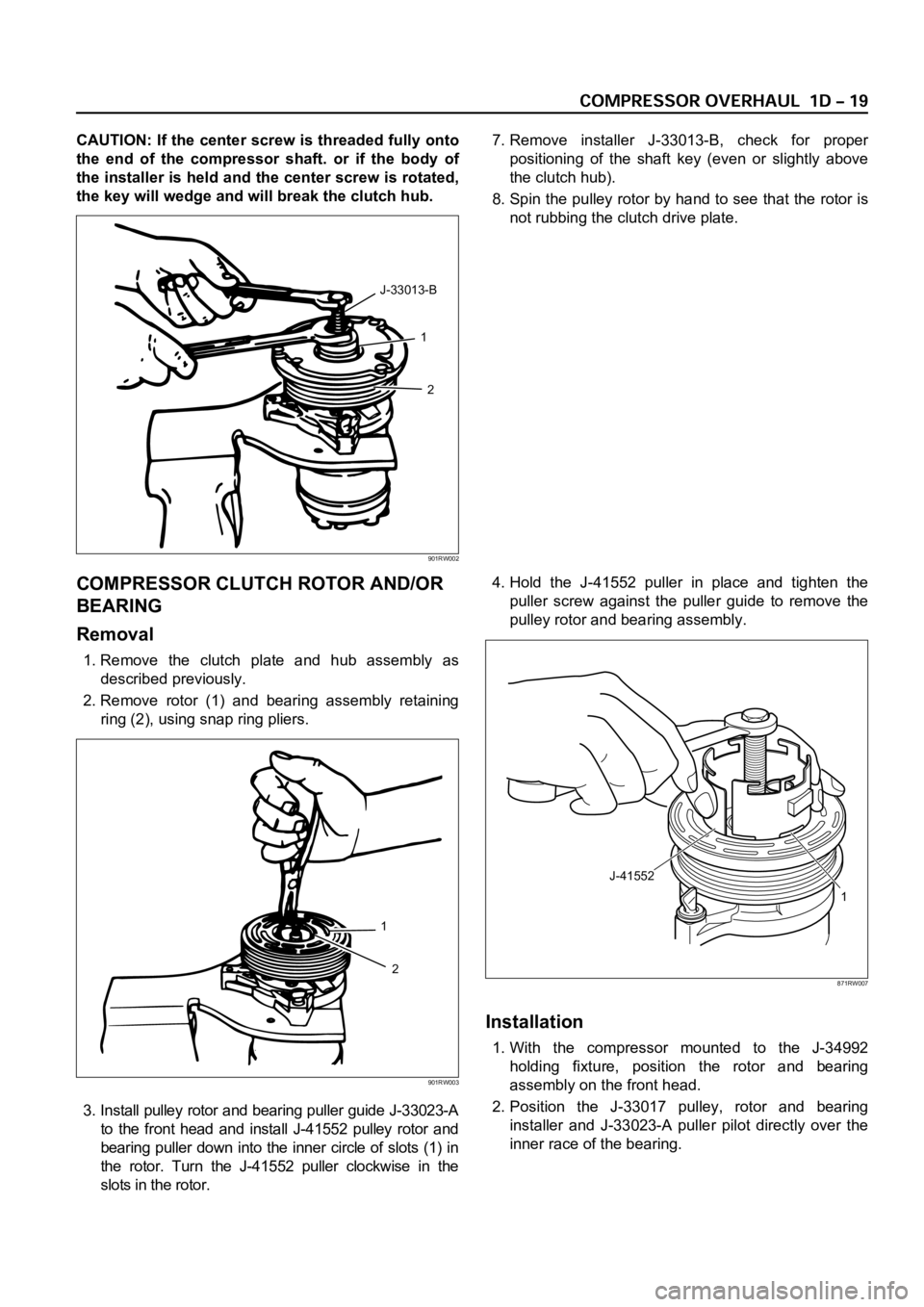
provide an interference fit in the hub key groove.2. Be sure the frictional surface of the clutch plate and
the clutch rotor (2) are clean before installing the
clutch plate and hub assembly (1).
3. Align the shaft key (4) with the shaft keyway (3) and
place the clutch plate and the hub assembly onto
the compressor shaft.
4. Remove the forcing tip on J-33013-B clutch plate
and hub assembly installer-remover center screw
and reverse the body direction on the center screw,
as shown in Figure.
5. Install the clutch plate and hub installer-remover J-
33013-B with bearing as shown in Figure.
The body of the J-33013-B installer-remover should
be backed off sufficiently to allow the center screw to
be threaded onto the end of the compressor shaft.
6. Hold the center screw with a wrench. Tighten the
hex portion of the installer-remover J-33013-B body
to press the hub onto the shaft. Tighten the body
several turns, remove the installer and check to see
that the shaft key is still in place in the keyway
before installing the clutch plate and hub
assembly to its finial position.The air gap (2)
between frictional surfaces of the clutch plate and
clutch rotor should be 0.50–0.76 mm (.020–.030 in).
1
J-33013-B
J-33026-1
J-33026
901RW001
4
31
2
871RW003
Page 3778 of 6000

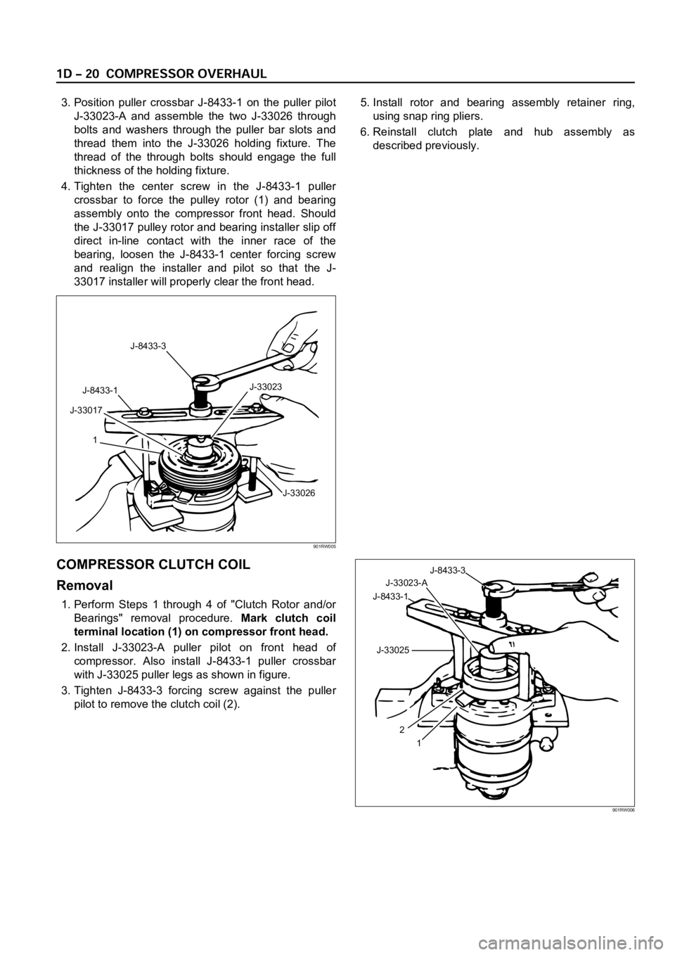
CAUTION: If the center screw is threaded fully onto
the end of the compressor shaft. or if the body of
the installer is held and the center screw is rotated,
the key will wedge and will break the clutch hub.7. Remove installer J-33013-B, check for proper
positioning of the shaft key (even or slightly above
the clutch hub).
8. Spin the pulley rotor by hand to see that the rotor is
not rubbing the clutch drive plate.
COMPRESSOR CLUTCH ROTOR AND/OR
BEARING
Removal
1. Remove the clutch plate and hub assembly as
described previously.
2. Remove rotor (1) and bearing assembly retaining
ring (2), using snap ring pliers.
3. Install pulley rotor and bearing puller guide J-33023-A
to the front head and install J-41552 pulley rotor and
bearing puller down into the inner circle of slots (1) in
the rotor. Turn the J-41552 puller clockwise in the
slots in the rotor.4. Hold the J-41552 puller in place and tighten the
puller screw against the puller guide to remove the
pulley rotor and bearing assembly.
Installation
1. With the compressor mounted to the J-34992
holding fixture, position the rotor and bearing
assembly on the front head.
2. Position the J-33017 pulley, rotor and bearing
installer and J-33023-A puller pilot directly over the
inner race of the bearing.
1
2 J-33013-B
901RW002
1
2
901RW003
J-41552
1
871RW007
Page 3779 of 6000

3. Position puller crossbar J-8433-1 on the puller pilot
J-33023-A and assemble the two J-33026 through
bolts and washers through the puller bar slots and
thread them into the J-33026 holding fixture. The
thread of the through bolts should engage the full
thickness of the holding fixture.
4. Tighten the center screw in the J-8433-1 puller
crossbar to force the pulley rotor (1) and bearing
assembly onto the compressor front head. Should
the J-33017 pulley rotor and bearing installer slip off
direct in-line contact with the inner race of the
bearing, loosen the J-8433-1 center forcing screw
and realign the installer and pilot so that the J-
33017 installer will properly clear the front head.5. Install rotor and bearing assembly retainer ring,
using snap ring pliers.
6. Reinstall clutch plate and hub assembly as
described previously.
COMPRESSOR CLUTCH COIL
Removal
1. Perform Steps 1 through 4 of "Clutch Rotor and/or
Bearings" removal procedure. Mark clutch coil
terminal location (1) on compressor front head.
2. Install J-33023-A puller pilot on front head of
compressor. Also install J-8433-1 puller crossbar
with J-33025 puller legs as shown in figure.
3. Tighten J-8433-3 forcing screw against the puller
pilot to remove the clutch coil (2).
J-8433-3
J-33023
J-33026 J-8433-1
J-33017
1
901RW005
J-33023-AJ-8433-3
J-8433-1
J-33025
1 2
901RW006