Page 2659 of 6000
3.0
W
3.0
L/R 3.0
L/B
0.5
O/G
AUDIO CIGARETTE
LIGHTERBLOWER
MOTORMAGNETIC
CLUTCHPOWER
WINDOW
RELAY
(2)STOPLIGHT AUDIO
(14)
DOME LIGHT FRT DOOR LOCK &
POWER WINDOW SW RR DEFOGGER C-11 10A
AUDIO
(ACC)
MIRROR
0.5
BRC-20 10A
AIR CON
0.85
G/WC-14 15A
STOP
A/T CONT
1.25
R/WC-15 20A
AUDIO (B)
3.0
L/OC-17 25A
RR
DEFOG
FUSE BOX
1.25
O/BC-12 20A
CIGAR
3.0
LC-19 25A
BLOWER
3.0
B/L 3.0
W5.0
W 5.0
W
5.0
W
C/B-2 30A
P/W,P/S,
S/R
0.5
R/WC-16 10A
CLOCK (B)
ROOM
1.25
LG/WC-18 20A
DOOR
LOCK
HEATER &
A/C RELAY
B-36
2
B-364
D08RWB21
Page 2866 of 6000
5
I-6
11
12
H-26
0.5
L/W0.5
L/W0.5
L/W0.5
R/B
0.85
R/B
0.75
R/B
0.5
L/B
0.5
L/B
0.5
L/B
0.5
L/B(A/T)
0.5
L/B 0.5
LG0.5
BR/Y0.5
GR/G
0.5
B
2.0
B 3.0
B/Y
0.85
L/W
0.5
L/W
0.5
P/B0.3
R/G 0.85
L/W0.5
L/W
0.85
G/R
0.5
P/B C-4 15A
ELEC.IGN.C-3 10A
TURN,BACK
CRUISE
MAIN
SWCLUTCH
SW
(M/T)MODE
SW COMBINATION
SW
CRUISE CONTROL UNIT
STARTER SW
(IG1)
BODY-LH 20
H-25
4
I-6
1
B-9
TAIL RELAY
(4)
ILLUMINATION
CONTROLLER(3)
PCM
(F2)
2
I-6
1
B-16 6
I-6
B-529
B-5212
10
B-52
11
B-52
13
B-52
4
B-93
B-910
B-912
B-9
B-1
2
B-16
16
B-9 B-9
M-25H-53H-7
12B-93 3 7H-88M-256H-1117
SET
RESUME
CANCEL
D08RW661
Page 2869 of 6000
5
I-6
11
6
H-48
0.5
L/W0.5
L/W0.5
L/W0.85
R/B
0.85
R/B
0.75
R/B
0.5
L/B
0.5
L/B
0.5
L/B
0.5
L/B(A/T)
0.5
L/B 0.5
LG0.5
BR/Y0.5
GR/G
0.5
B
2.0
B 3.0
B/Y
0.5
L/W
0.5
L/W
0.5
P/B0.3
R/G 0.85
L/W 0.85
L/W
0.85
G/R
0.5
P/B C-4 10A
ELEC.IGN.C-3 10A
TURN,BACK
CRUISE
MAIN
SWCLUTCH
SW
(M/T)MODE
SW COMBINATION
SW
CRUISE CONTROL UNIT
STARTER SW
(IG1)
BODY-RH 5
H-25
4
I-6
1
B-9
TAIL RELAY
(4)
ILLUMINATION
CONTROLLER(3)
PCM
(F2)
2
I-6
1
B-16 6
I-6
B-529
B-5212
10
B-52
11
B-52
13
B-52
4
B-93
B-910
B-912
B-9
B-2
2
B-16
16
B-9 B-9
M-25H-53H-8
12B-92 3 7H-88M-256H-114
SET
RESUME
CANCEL
D08RW957
Page 2872 of 6000

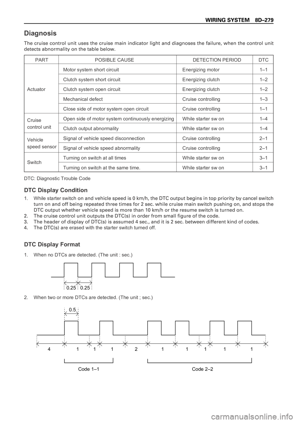
Diagnosis
PART POSIBLE CAUSE DETECTION PERIOD DTC
Motor system short circuit Energizing motor 1–1
Clutch system short circuit Energizing clutch 1–2
Actuator Clutch system open circuit Energizing clutch 1–2
Mechanical defect Cruise controlling 1–3
Close side of motor system open circuit Cruise controlling 1–1
CruiseOpen side of motor system continuously energizing While starter sw on 1–4
control unit
Clutch output abnormality While starter sw on 1–4
VehicleSignal of vehicle speed disconnection Cruise controlling 2–1
speed sensor
Signal of vehicle speed abnormality Cruise controlling 2–1
SwitchTurning on switch at all times While starter sw on 3–1
Turning on switch at the same time. While starter sw on 3–1
DTC: Diagnostic Trouble Code
DTC Display Condition
1. While starter swi
erased with the starter switch turned off.
DTC Display Format
1. When no DTCs are detected. (The unit : sec.)
2. When two or more DTCs are detected. (The unit ; sec.)
0.25 0.25
Code 1–1 Code 2–2 410.5
11 1 1 1 1 12
Page 2874 of 6000

DTC 1–2 Clutch System Open or Short Circuit
STEP ACTION VALUE(S) YES NO
1. Turn the starter switch off.
2. Disconnect the actuator connector C–37.
3. Measure resistance between actuator side connector
terminal 3 and 4.
Is the resistance within range specified in the value(s)
column?
1. Disconnect the brake switch connector B–13.
2. Check continuity between switch side connector terminal 2
and 3.
Is there continuity between terminals?
1. Reconnect the brake switch connector B–13.
2. Check continuity between harness side connector B–9
terminal 6 and connector C–37 terminal 3, connector C–37
terminal 4 and connector B–9 terminal 8.
Is there continuity between terminals?
Is there continuity between harness side connector C–37
terminal 3 and the ground, connector C–37 terminal 4 and
the ground, connector B–9 terminal 6 and the ground?
Are the results same as specified in the value(s) column?34.7 – 42.4
–
–
No continuityGo to
step 2
Go to
step 3
Go to
step 4
Replace
the control
unitReplace
the
actuator
Adjust the
switch or
replace it
Repair
open
circuit
Repair
short
circuit 1
2
3
4
Page 2998 of 6000

WIRING SYSTEM 8D–405
TERMINAL
CONNECTIONCHECK
OPERATIONCIRCUIT
NO. ITEM CONDITION
1 FRT door switch–LH, RH ContinuityOpen door Continuity
Close door No continuity
2 RR door switch–LH, RH ContinuityOpen door Continuity
Close door No continuity
3— — – –
4 Door lock key switch–LH, RH Continuity Lock with key Continuity
5 FRT door lock switch–LH, RH Continuity Lock Continuity
6 Tailgate switch ContinuityOpen tailgate Continuity
Close tailgate No continuity
8 Anti–theft horn Voltage – Approx. 12V
10 Battery Voltage – Approx. 12V
11 Door switch ContinuityUnlock with locking knob Continuity
Lock with locking knob No continuity
12 Engine hood switch ContinuityOpen engine hood Continuity
Close engine hood No continuity
13 Detect switch ContinuityUnlock with key Continuity
Lock with key No continuity
14 Door lock key switch Continuity Unlock Continuity
15 FRT door lock switch–LH, RH Continuity Unlock Continuity
16 Tamper switch Continuity – No continuity
17 Ground Continuity – Continuity
18 Starter switch Voltage Starter switch “ACC” Approx. 12V
19 Indicator light Voltage – Approx. 12V
20 Dome light Voltage Dome light “DOOR” position Approx. 12V
21 Anti-theft relay Voltage – Approx. 12V
22 Starter relay VoltageMode switch “P” or “N” Approx. 12V
Clutch pedal depressed Approx. 12V
Check the anti–theft & keyless entry control unit harness side connector B–20 by using a circuit tester.
Page 3133 of 6000
D08RW611
FRT AXLE
SW T.O.D. CONTROL UNIT
3C-16
FENDER-LH
M-22 0.5
L/Y
0.5 G 0.5
G/W 0.5
G/R 0.5
G/Y 0.5
LB
0.5
G/R 0.5
G
0.5 G 0.5
G
0.5
G/W 0.5
G/R 0.5
G/R 0.5
G/Y 0.5
LB
0.5
L/Y
0.5
L/Y
0.5
BR/R
0.5 P
0.5 Y
0.5 Y
0.5 B 0.5
B
0.5
B
0.85 B 0.5
L/Y
2
M-22 5
H-10
1 22
B-68
5
H-12 10
H-10
2
M-23 1
M-23 3
H-10
B-67
5
H-7 2
FRT SPEED
SENSOR
(TRANSFER) RR SPEED
SENSOR
(TRANSFER) CLUTCH
SOLENOID
(TRANSFER)
M-24 1
M-24
2A-3 3
H-49
B-67
7
6A-3 14
H-49
B-68
12
10A-3 13
H-49
2H-49 7H-49
B-67
10
5A-3
9A-3 1A-3
12
H-49
B-68
11
8A-3
H-49
B-67 4
4
VSV;
FRT AXLE(C) VSV;
FRT AXLE(D)
Page 3361 of 6000

8H–22SECURITY AND LOCKS
Anti-theft System
General Description
The circuit consists of the starter switch, anti-theft &
keyless entry control unit, anti-theft horn, front door and
tailgate key switch (detect and tamper switch), door lock
(& power window) switch, door lock actuator for each
door, engine hood switch, clutch start switch (M/T),
ANTI-THEFT indicator light and mode switch (A/T).
The system operates as follows: After locking the starter
switch and removing the starter key (this sets the alarm),
if the door is unlocked in any way other than with the
proper key, the headlights start flashing, the horn sounds,
and the starter circuit is disabled. (However, the engine
hood and all the doors must be locked and closed.)
Once the system has been placed in the warning or alarm
condition, it can be released only when the starter switch
is shifted from “OFF” to “ACC” by the starter key, or when
the lock of the front door or the tailgate is released (to
activate the detect switch) by the starter key.
Anti-theft & Keyless Entry Control
Unit Removal
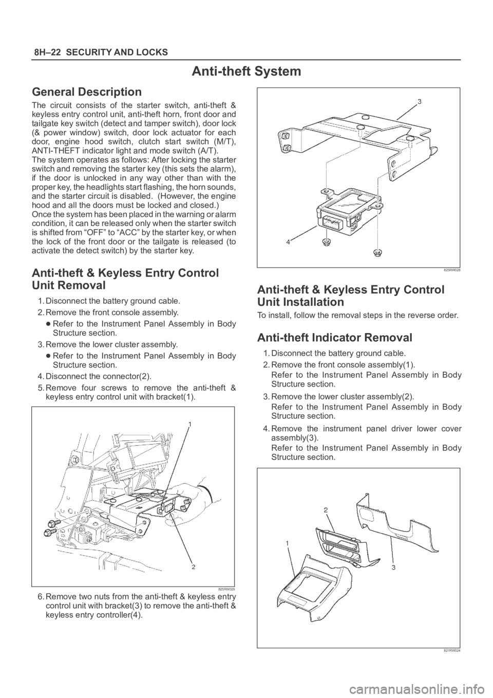
1. Disconnect the battery ground cable.
2. Remove the front console assembly.
Refer to the Instrument Panel Assembly in Body
Structure section.
3. Remove the lower cluster assembly.
Refer to the Instrument Panel Assembly in Body
Structure section.
4. Disconnect the connector(2).
5. Remove four screws to remove the anti-theft &
keyless entry control unit with bracket(1).
825RW029
6. Remove two nuts from the anti-theft & keyless entry
control unit with bracket(3) to remove the anti-theft &
keyless entry controller(4).
825RW028
Anti-theft & Keyless Entry Control
Unit Installation
To install, follow the removal steps in the reverse order.
Anti-theft Indicator Removal
1. Disconnect the battery ground cable.
2. Remove the front console assembly(1).
Refer to the Instrument Panel Assembly in Body
Structure section.
3. Remove the lower cluster assembly(2).
Refer to the Instrument Panel Assembly in Body
Structure section.
4. Remove the instrument panel driver lower cover
assembly(3).
Refer to the Instrument Panel Assembly in Body
Structure section.
821RW024