1998 OPEL FRONTERA clutch
[x] Cancel search: clutchPage 4728 of 6000
6E–71 ENGINE DRIVEABILITY AND EMISSIONS
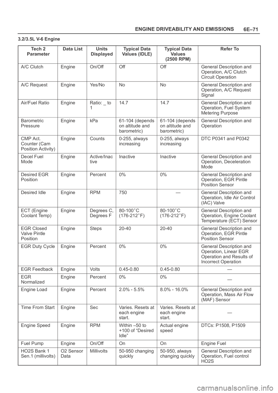
3.2/3.5L V-6 Engine
Te c h 2
Parameter
Data ListUnits
DisplayedTypical Data
Values (IDLE)Typical Data
Va l u e s
(2500 RPM)Refer To
A/C ClutchEngineOn/OffOffOffGeneral Description and
Operation, A/C Clutch
Circuit Operation
A/C RequestEngineYe s / N oNoNoGeneral Description and
Operation, A/C Request
Signal
Air/Fuel RatioEngineRatio: _ to
114.714.7General Description and
Operation, Fuel System
Metering Purpose
Barometric
PressureEnginekPa61-104 (depends
on altitude and
barometric)61-104 (depends
on altitude and
barometric)General Description and
Operation
CMP Act.
Counter (Cam
Position Activity)EngineCounts0-255, always
increasing0-255, always
increasingDTC P0341 and P0342
Decel Fuel
ModeEngineActive/Inac
tiveInactiveInactiveGeneral Description and
Operation, Deceleration
Mode
Desired EGR
PositionEnginePercent0%0%General Description and
Operation, EGR Pintle
Position Sensor
Desired IdleEngineRPM750—General Description and
Operation, Idle Air Control
(IAC) Valve
ECT (Engine
Coolant Temp)EngineDegrees C,
Degrees F80-100C
(176-212
F)
80-100C
(176-212
F)
General Description and
Operation, Engine Coolant
Temperature (ECT) Sensor
EGR Closed
Valve Pintle
PositionEngineSteps20-4020-40General Description and
Operation, EGR Pintle
Position Sensor
EGR Duty CycleEnginePercent0%0%General Description and
Operation, Linear EGR
Operation and Results of
Incorrect Operation
EGR FeedbackEngineVo l t s0.45-0.800.45-0.80—
EGR
NormalizedEnginePercent0%0%—
Engine LoadEnginePercent2.0% - 5.5%8.0% - 16.0%General Description and
Operation, Mass Air Flow
(MAF) Sensor
Time From StartEngineSecVaries. Resets at
each engine
start.Varies. Resets at
each engine
start.
—
Engine SpeedEngineRPMWithin –50 to
+100 of “Desired
Idle”Actual engine
speedDTCs: P1508, P1509
Fuel PumpEngineOn/OffOnOnEngine Fuel
HO2S Bank 1
Sen.1 (millivolts)O2 Sensor
DataMillivolts50-950 changing
quickly50-950, always
changing quicklyGeneral Description and
Operation, Fuel control
HO2S
Page 4916 of 6000
6E–259 ENGINE DRIVEABILITY AND EMISSIONS
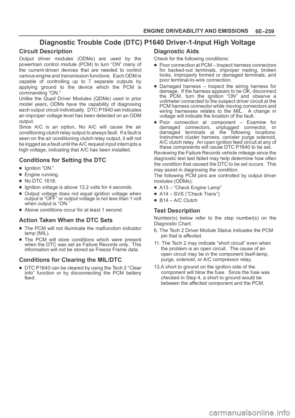
Diagnostic Trouble Code (DTC) P1640 Driver-1-Input High Voltage
Circuit Description
Output driver modules (ODMs) are used by the
powertrain control module (PCM) to turn “ON” many of
the current-driven devices that are needed to control
various engine and transmission functions. Each ODM is
capable of controlling up to 7 separate outputs by
applying ground to the device which the PCM is
commanding “ON.”
Unlike the Quad Driver Modules (QDMs) used in prior
model years, ODMs have the capability of diagnosing
each output circuit individually. DTC P1640 set indicates
an improper voltage level has been detected on an ODM
output.
Since A/C is an option, No A/C will cause the air
conditioning clutch relay output to always fault. If a fault is
seen on the air conditioning clutch relay output, it will not
be logged as a fault until the A/C request input interrupts a
high voltage, indicating that A/C has been installed.
Conditions for Setting the DTC
Ignition “ON.”
Engine running.
No DTC 1618.
Ignition voltage is above 13.2 volts for 4 seconds.
Output voltage does not equal ignition voltage when
output is “OFF” or output voltage is not less than 1 volt
when output is “ON.”
Above conditions occur for at least 1 second.
Action Taken When the DTC Sets
The PCM will not illuminate the malfunction indicator
lamp (MIL).
The PCM will store conditions which were present
when the DTC was set as Failure Records only. This
information will not be stored as Freeze Frame data.
Conditions for Clearing the MIL/DTC
DTC P1640 can be cleared by using the Tech 2 “Clear
Info” function or by disconnecting the PCM battery
feed.
Diagnostic Aids
Check for the following conditions:
Poor connection at PCM – Inspect harness connectors
for backed-out terminals, improper mating, broken
locks, improperly formed or damaged terminals, and
poor terminal-to-wire connection.
Damaged harness – Inspect the wiring harness for
damage, If the harness appears to be OK, disconnect
the PCM, turn the ignition “ON” and observe a
voltmeter connected to the suspect driver circuit at the
PCM harness connector while moving connectors and
wiring harnesses relates to the MIL. A change in
voltage will indicate the location of the fault.
Poor connection at component – Examine for
damaged connectors, unplugged connector, or
damaged terminals at the following locations:
Instrument cluster harness, canister purge solenoid,
A/C clutch relay. An open ignition feed circuit at any of
these components will cause DTC P1640 to be set.
Reviewing the Failure Records vehicle mileage since the
diagnostic test last failed may help determine how often
the condition that caused the DTC to be set occurs. This
may assist in diagnosing the condition.
The following PCM pins are controlled by output driver
modules (ODMs):
A13 – “Check Engine Lamp”
A14 – SVS (”Check Trans”)
B14 – A/C Clutch
Test Description
Number(s) below refer to the step number(s) on the
Diagnostic Chart.
6. The Tech 2 Driver Module Status indicates the PCM
pin that is affected.
11. The Tech 2 may indicate “short circuit” even when
the problem is an open circuit. The cause of an
open circuit may be in the component itself-lamp,
purge, solenoid, or A/C compressor relay.
13.A short to ground on the ignition side of the
component will blow the fuse. Since the fuse was
checked in Step 4, a short to ground would be
between the affected component and the PCM.
Page 4919 of 6000
6E–262
ENGINE DRIVEABILITY AND EMISSIONS
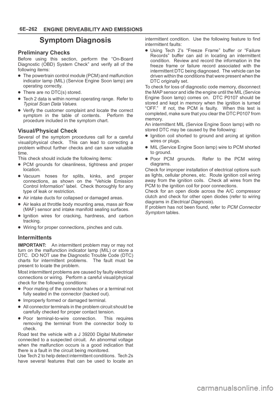
Symptom Diagnosis
Preliminary Checks
Before using this section, perform the “On-Board
Diagnostic (OBD) System Check” and verify all of the
following items:
The powertrain control module (PCM) and malfunction
indicator lamp (MIL) (Service Engine Soon lamp) are
operating correctly.
There are no DTC(s) stored.
Tech 2 data is within normal operating range. Refer to
Typical Scan Data Values.
Verify the customer complaint and locate the correct
symptom in the table of contents. Perform the
procedure included in the symptom chart.
Visual/Physical Check
Several of the symptom procedures call for a careful
visual/physical check. This can lead to correcting a
problem without further checks and can save valuable
time.
This check should include the following items:
PCM grounds for cleanliness, tightness and proper
location.
Vacuum hoses for splits, kinks, and proper
connections, as shown on the “Vehicle Emission
Control Information” label. Check thoroughly for any
type of leak or restriction.
Air intake ducts for collapsed or damaged areas.
Air leaks at throttle body mounting area, mass air flow
(MAF) sensor and intake manifold sealing surfaces.
Ignition wires for cracking, hardness, and carbon
tracking.
Wiring for proper connections, pinches and cuts.
Intermittents
IMPORTANT:An intermittent problem may or may not
turn on the malfunction indicator lamp (MIL) or store a
DTC. DO NOT use the Diagnostic Trouble Code (DTC)
charts for intermittent problems. The fault must be
present to locate the problem.
Most intermittent problems are caused by faulty electrical
connections or wiring. Perform a careful visual/physical
check for the following conditions:
Poor mating of the connector halves or a terminal not
fully seated in the connector (backed out).
Improperly formed or damaged terminal.
All connector terminals in the problem circuit should be
carefully checked for proper contact tension.
Poor terminal-to-wire connection. This requires
removing the terminal from the connector body to
check.
Road test the vehicle with a J 39200 Digital Multimeter
connected to a suspected circuit. An abnormal voltage
when the malfunction occurs is a good indication that
there is a fault in the circuit being monitored.
Use Tech 2 to help detect intermittent conditions. Tech 2s
have several features that can be used to locate anintermittent condition. Use the following feature to find
intermittent faults:
Using Tech 2’s “Freeze Frame” buffer or “Failure
Records” buffer can aid in locating an intermittent
condition. Review and record the information in the
freeze frame or failure record associated with the
intermittent DTC being diagnosed. The vehicle can be
driven within the conditions that were present when the
DTC originally set.
To check for loss of diagnostic code memory, disconnect
the MAP sensor and idle the engine until the MIL (Service
Engine Soon lamp) comes on. DTC P0107 should be
stored and kept in memory when the ignition is turned
“OFF.” If not, the PCM is faulty. When this test is
completed, make sure that you clear the DTC P0107 from
memory.
An intermittent MIL (Service Engine Soon lamp) with no
stored DTC may be caused by the following:
Ignition coil shorted to ground and arcing at ignition
wires or plugs.
MIL (Service Engine Soon lamp) wire to PCM shorted
to ground.
Poor PCM grounds. Refer to the PCM wiring
diagrams.
Check for improper installation of electrical options such
as lights, cellular phones, etc. Route ignition coil wiring
away from the ignition coils. Check all wires from the
PCM to the ignition coil for poor connections.
Check for an open diode across the A/C compressor
clutch and check for other open diodes (refer to wiring
diagrams in
Electrical Diagnosis).
If problem has not been found, refer to
PCM Connector
Symptom
tables.
Page 4922 of 6000
6E–265 ENGINE DRIVEABILITY AND EMISSIONS
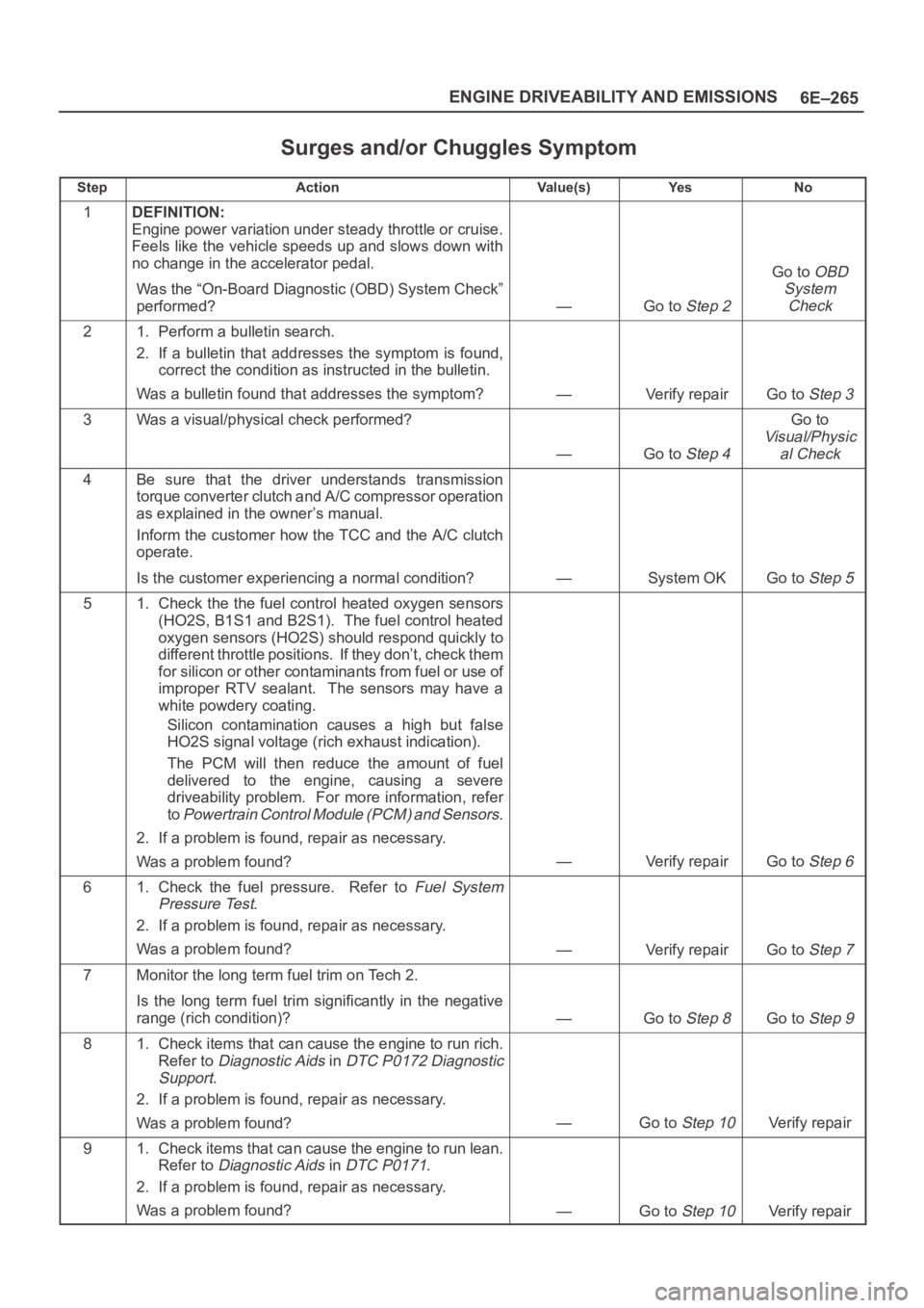
Surges and/or Chuggles Symptom
StepActionVa l u e ( s )Ye sNo
1DEFINITION:
Engine power variation under steady throttle or cruise.
Feels like the vehicle speeds up and slows down with
no change in the accelerator pedal.
Was the “On-Board Diagnostic (OBD) System Check”
performed?
—Go to Step 2
Go to OBD
System
Check
21. Perform a bulletin search.
2. If a bulletin that addresses the symptom is found,
correct the condition as instructed in the bulletin.
Was a bulletin found that addresses the symptom?
—Verify repairGo to Step 3
3Was a visual/physical check performed?
—Go to Step 4
Go to
Visual/Physic
al Check
4Be sure that the driver understands transmission
torque converter clutch and A/C compressor operation
as explained in the owner’s manual.
Inform the customer how the TCC and the A/C clutch
operate.
Is the customer experiencing a normal condition?
—System OKGo to Step 5
51. Check the the fuel control heated oxygen sensors
(HO2S, B1S1 and B2S1). The fuel control heated
oxygen sensors (HO2S) should respond quickly to
different throttle positions. If they don’t, check them
for silicon or other contaminants from fuel or use of
improper RTV sealant. The sensors may have a
white powdery coating.
Silicon contamination causes a high but false
HO2S signal voltage (rich exhaust indication).
The PCM will then reduce the amount of fuel
delivered to the engine, causing a severe
driveability problem. For more information, refer
to
Powertrain Control Module (PCM) and Sensors.
2. If a problem is found, repair as necessary.
Was a problem found?
—Verify repairGo to Step 6
61. Check the fuel pressure. Refer to Fuel System
Pressure Test
.
2. If a problem is found, repair as necessary.
Was a problem found?
—Verify repairGo to Step 7
7Monitor the long term fuel trim on Tech 2.
Is the long term fuel trim significantly in the negative
range (rich condition)?
—Go to Step 8Go to Step 9
81. Check items that can cause the engine to run rich.
Refer to
Diagnostic Aids in DTC P0172 Diagnostic
Support
.
2. If a problem is found, repair as necessary.
Was a problem found?
—Go to Step 10Verify repair
91. Check items that can cause the engine to run lean.
Refer to
Diagnostic Aids in DTC P0171.
2. If a problem is found, repair as necessary.
Was a problem found?
—Go to Step 10Verify repair
Page 4926 of 6000
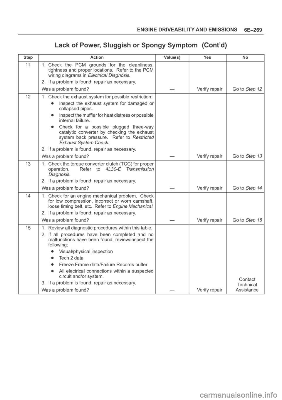
6E–269 ENGINE DRIVEABILITY AND EMISSIONS
Lack of Power, Sluggish or Spongy Symptom
StepNo Ye s Va l u e ( s ) Action
111. Check the PCM grounds for the cleanliness,
tightness and proper locations. Refer to the PCM
wiring diagrams in
Electrical Diagnosis.
2. If a problem is found, repair as necessary.
Was a problem found?
—Verify repairGo to Step 12
121. Check the exhaust system for possible restriction:
Inspect the exhaust system for damaged or
collapsed pipes.
Inspect the muffler for heat distress or possible
internal failure.
Check for a possible plugged three-way
catalytic converter by checking the exhaust
system back pressure. Refer to
Restricted
Exhaust System Check
.
2. If a problem is found, repair as necessary.
Was a problem found?
—Verify repairGo to Step 13
131. Check the torque converter clutch (TCC) for proper
operation. Refer to
4L30-E Transmission
Diagnosis
.
2. If a problem is found, repair as necessary.
Was a problem found?
—Verify repairGo to Step 14
141. Check for an engine mechanical problem. Check
for low compression, incorrect or worn camshaft,
loose timing belt, etc. Refer to
Engine Mechanical.
2. If a problem is found, repair as necessary.
Was a problem found?
—Verify repairGo to Step 15
151. Review all diagnostic procedures within this table.
2. If all procedures have been completed and no
malfunctions have been found, review/inspect the
following:
Visual/physical inspection
Te c h 2 d a t a
Freeze Frame data/Failure Records buffer
All electrical connections within a suspected
circuit and/or system.
3. If a problem is found, repair as necessary.
Was a problem found?
—Verify repair
Contact
Te c h n i c a l
Assistance
Page 4946 of 6000
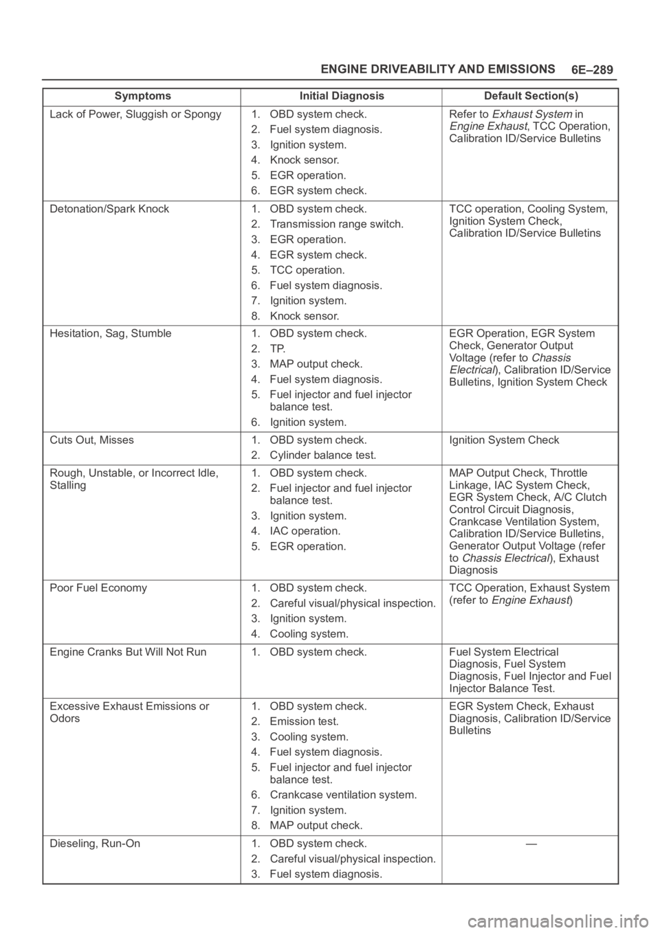
6E–289 ENGINE DRIVEABILITY AND EMISSIONS
Symptoms Default Section(s)Initial Diagnosis
Lack of Power, Sluggish or Spongy1. OBD system check.
2. Fuel system diagnosis.
3. Ignition system.
4. Knock sensor.
5. EGR operation.
6. EGR system check.Refer to Exhaust System in
Engine Exhaust, TCC Operation,
Calibration ID/Service Bulletins
Detonation/Spark Knock1. OBD system check.
2. Transmission range switch.
3. EGR operation.
4. EGR system check.
5. TCC operation.
6. Fuel system diagnosis.
7. Ignition system.
8. Knock sensor.TCC operation, Cooling System,
Ignition System Check,
Calibration ID/Service Bulletins
Hesitation, Sag, Stumble1. OBD system check.
2. TP.
3. MAP output check.
4. Fuel system diagnosis.
5. Fuel injector and fuel injector
balance test.
6. Ignition system.EGR Operation, EGR System
Check, Generator Output
Voltage (refer to
Chassis
Electrical
), Calibration ID/Service
Bulletins, Ignition System Check
Cuts Out, Misses1. OBD system check.
2. Cylinder balance test.Ignition System Check
Rough, Unstable, or Incorrect Idle,
Stalling1. OBD system check.
2. Fuel injector and fuel injector
balance test.
3. Ignition system.
4. IAC operation.
5. EGR operation.MAP Output Check, Throttle
Linkage, IAC System Check,
EGR System Check, A/C Clutch
Control Circuit Diagnosis,
Crankcase Ventilation System,
Calibration ID/Service Bulletins,
Generator Output Voltage (refer
to
Chassis Electrical), Exhaust
Diagnosis
Poor Fuel Economy1. OBD system check.
2. Careful visual/physical inspection.
3. Ignition system.
4. Cooling system.TCC Operation, Exhaust System
(refer to
Engine Exhaust)
Engine Cranks But Will Not Run1. OBD system check.Fuel System Electrical
Diagnosis, Fuel System
Diagnosis, Fuel Injector and Fuel
Injector Balance Test.
Excessive Exhaust Emissions or
Odors1. OBD system check.
2. Emission test.
3. Cooling system.
4. Fuel system diagnosis.
5. Fuel injector and fuel injector
balance test.
6. Crankcase ventilation system.
7. Ignition system.
8. MAP output check.EGR System Check, Exhaust
Diagnosis, Calibration ID/Service
Bulletins
Dieseling, Run-On1. OBD system check.
2. Careful visual/physical inspection.
3. Fuel system diagnosis.—
Page 4992 of 6000
6E–335 ENGINE DRIVEABILITY AND EMISSIONS
General Description
General Description (PCM and
Sensors)
58X Reference PCM Input
The powertrain control module (PCM) uses this signal
from the crankshaft position (CKP) sensor to calculate
engine RPM and crankshaft position at all engine speeds.
The PCM also uses the pulses on this circuit to initiate
injector pulses. If the PCM receives no pulses on this
circuit, DTC P0337 will set. The engine will not start and
run without using the 58X reference signal.
A/C Request Signal
This signal tells the PCM when the A/C mode is selected
at the A/C control head. The PCM uses this to adjust the
idle speed before turning “ON” the A/C clutch. The A/C
compressor will be inoperative if this signal is not
available to the PCM.
Refer to
A/C Clutch Circuit Diagnosis for A/C wiring
diagrams and diagnosis for the A/C electrical system.
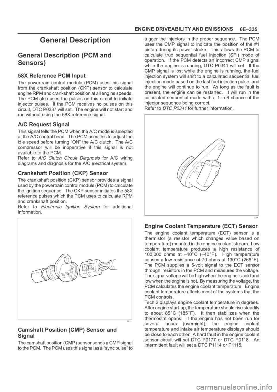
Crankshaft Position (CKP) Sensor
The crankshaft position (CKP) sensor provides a signal
used by the powertrain control module (PCM) to calculate
the ignition sequence. The CKP sensor initiates the 58X
reference pulses which the PCM uses to calculate RPM
and crankshaft position.
Refer to
Electronic Ignition System for additional
information.
0013
Camshaft Position (CMP) Sensor and
Signal
The camshaft position (CMP) sensor sends a CMP signal
t o t h e P C M . T h e P C M u s e s t h i s s i g n a l a s a “ s y n c p u l s e ” t otrigger the injectors in the proper sequence. The PCM
uses the CMP signal to indicate the position of the #1
piston during its power stroke. This allows the PCM to
calculate true sequential fuel injection (SFI) mode of
operation. If the PCM detects an incorrect CMP signal
while the engine is running, DTC P0341 will set. If the
CMP signal is lost while the engine is running, the fuel
injection system will shift to a calculated sequential fuel
injection mode based on the last fuel injection pulse, and
the engine will continue to run. As long as the fault is
present, the engine can be restarted. It will run in the
calculated sequential mode with a 1-in-6 chance of the
injector sequence being correct.
Refer to
DTC P0341 for further information.
0014
Engine Coolant Temperature (ECT) Sensor
The engine coolant temperature (ECT) sensor is a
thermistor (a resistor which changes value based on
temperature) mounted in the engine coolant stream. Low
coolant temperature produces a high resistance of
100,000 ohms at –40
C (–40F). High temperature
causes a low resistance of 70 ohms at 130
C (266F).
The PCM supplies a 5-volt signal to the ECT sensor
through resistors in the PCM and measures the voltage.
The signal voltage will be high when the engine is cold and
low when the engine is hot. By measuring the voltage, the
PCM calculates the engine coolant temperature. Engine
coolant temperature affects most of the systems that the
PCM controls.
Tech 2 displays engine coolant temperature in degrees.
After engine start-up, the temperature should rise steadily
to about 85
C (185F). It then stabilizes when the
thermostat opens. If the engine has not been run for
several hours (overnight), the engine coolant
temperature and intake air temperature displays should
be close to each other. A hard fault in the engine coolant
sensor circuit will set DTC P0177 or DTC P0118. An
intermittent fault will set a DTC P1114 or P1115.
Page 4996 of 6000
6E–339 ENGINE DRIVEABILITY AND EMISSIONS
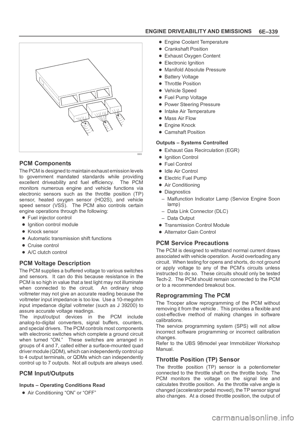
0005
PCM Components
The PCM is designed to maintain exhaust emission levels
to government mandated standards while providing
excellent driveability and fuel efficiency. The PCM
monitors numerous engine and vehicle functions via
electronic sensors such as the throttle position (TP)
sensor, heated oxygen sensor (HO2S), and vehicle
speed sensor (VSS). The PCM also controls certain
engine operations through the following:
Fuel injector control
Ignition control module
Knock sensor
Automatic transmission shift functions
Cruise control
A/C clutch control
PCM Voltage Description
The PCM supplies a buffered voltage to various switches
and sensors. It can do this because resistance in the
PCM is so high in value that a test light may not illuminate
when connected to the circuit. An ordinary shop
voltmeter may not give an accurate reading because the
voltmeter input impedance is too low. Use a 10-megohm
input impedance digital voltmeter (such as J 39200) to
assure accurate voltage readings.
The input/output devices in the PCM include
analog-to-digital converters, signal buffers, counters,
and special drivers. The PCM controls most components
with electronic switches which complete a ground circuit
when turned “ON.” These switches are arranged in
groups of 4 and 7, called either a surface-mounted quad
driver module (QDM), which can independently control up
to 4 output terminals, or QDMs which can independently
control up to 7 outputs. Not all outputs are always used.
PCM Input/Outputs
Inputs – Operating Conditions Read
Air Conditioning “ON” or “OFF”
Engine Coolant Temperature
Crankshaft Position
Exhaust Oxygen Content
Electronic Ignition
Manifold Absolute Pressure
Battery Voltage
Throttle Position
Vehicle Speed
Fuel Pump Voltage
Power Steering Pressure
Intake Air Temperature
Mass Air Flow
Engine Knock
Camshaft Position
Outputs – Systems Controlled
Exhaust Gas Recirculation (EGR)
Ignition Control
Fuel Control
Idle Air Control
Electric Fuel Pump
Air Conditioning
Diagnostics
– Malfunction Indicator Lamp (Service Engine Soon
lamp)
– Data Link Connector (DLC)
– Data Output
Transmission Control Module
Alternator Gain Control
PCM Service Precautions
The PCM is designed to withstand normal current draws
associated with vehicle operation. Avoid overloading any
circuit. When testing for opens and shorts, do not ground
or apply voltage to any of the PCM’s circuits unless
instructed to do so. These circuits should only be tested
Tech-2. The PCM should remain connected to the PCM
or to a recommended breakout box.
Reprogramming The PCM
The Trooper allow reprogramming of the PCM without
removing it from the vehicle . This provides a flexible and
cost-effective method of making changes in software
calibrations.
The service programming system (SPS) will not allow
incorrect software programming or incorrect calibration
changes.
Refer to the UBS 98model year Immobilizer Workshop
Manual.
Throttle Position (TP) Sensor
The throttle position (TP) sensor is a potentiometer
connected to the throttle shaft on the throttle body. The
PCM monitors the voltage on the signal line and
calculates throttle position. As the throttle valve angle is
changed (accelerator pedal moved), the TP sensor signal
also changes. At a closed throttle position, the output of