1998 OPEL FRONTERA clutch
[x] Cancel search: clutchPage 5690 of 6000
7A–1 AUTOMATIC TRANSMISSION (4L30–E)
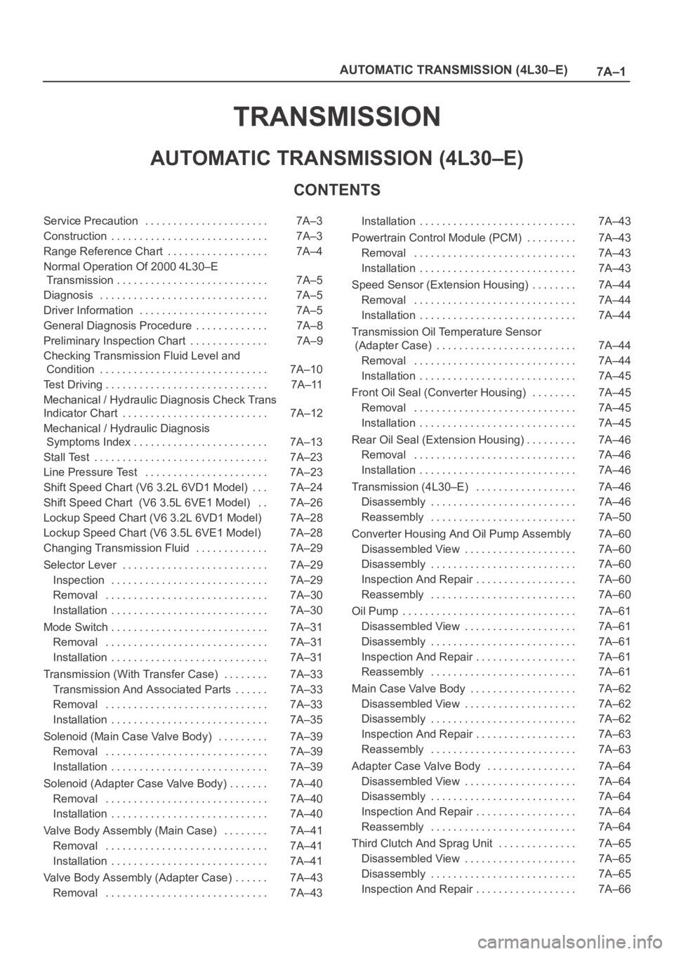
TRANSMISSION
AUTOMATIC TRANSMISSION (4L30–E)
CONTENTS
Service Precaution 7A–3. . . . . . . . . . . . . . . . . . . . . .
Construction 7A–3. . . . . . . . . . . . . . . . . . . . . . . . . . . .
Range Reference Chart 7A–4. . . . . . . . . . . . . . . . . .
Normal Operation Of 2000 4L30–E
Transmission 7A–5. . . . . . . . . . . . . . . . . . . . . . . . . . .
Diagnosis 7A–5. . . . . . . . . . . . . . . . . . . . . . . . . . . . . .
Driver Information 7A–5. . . . . . . . . . . . . . . . . . . . . . .
General Diagnosis Procedure 7A–8. . . . . . . . . . . . .
Preliminary Inspection Chart 7A–9. . . . . . . . . . . . . .
Checking Transmission Fluid Level and
Condition 7A–10. . . . . . . . . . . . . . . . . . . . . . . . . . . . . .
Test Driving 7A–11. . . . . . . . . . . . . . . . . . . . . . . . . . . . .
Mechanical / Hydraulic Diagnosis Check Trans
Indicator Chart 7A–12. . . . . . . . . . . . . . . . . . . . . . . . . .
Mechanical / Hydraulic Diagnosis
Symptoms Index 7A–13. . . . . . . . . . . . . . . . . . . . . . . .
Stall Test 7A–23. . . . . . . . . . . . . . . . . . . . . . . . . . . . . . .
Line Pressure Test 7A–23. . . . . . . . . . . . . . . . . . . . . .
Shift Speed Chart (V6 3.2L 6VD1 Model) 7A–24. . .
Shift Speed Chart (V6 3.5L 6VE1 Model) 7A–26. .
Lockup Speed Chart (V6 3.2L 6VD1 Model) 7A–28
Lockup Speed Chart (V6 3.5L 6VE1 Model) 7A–28
Changing Transmission Fluid 7A–29. . . . . . . . . . . . .
Selector Lever 7A–29. . . . . . . . . . . . . . . . . . . . . . . . . .
Inspection 7A–29. . . . . . . . . . . . . . . . . . . . . . . . . . . .
Removal 7A–30. . . . . . . . . . . . . . . . . . . . . . . . . . . . .
Installation 7A–30. . . . . . . . . . . . . . . . . . . . . . . . . . . .
Mode Switch 7A–31. . . . . . . . . . . . . . . . . . . . . . . . . . . .
Removal 7A–31. . . . . . . . . . . . . . . . . . . . . . . . . . . . .
Installation 7A–31. . . . . . . . . . . . . . . . . . . . . . . . . . . .
Transmission (With Transfer Case) 7A–33. . . . . . . .
Transmission And Associated Parts 7A–33. . . . . .
Removal 7A–33. . . . . . . . . . . . . . . . . . . . . . . . . . . . .
Installation 7A–35. . . . . . . . . . . . . . . . . . . . . . . . . . . .
Solenoid (Main Case Valve Body) 7A–39. . . . . . . . .
Removal 7A–39. . . . . . . . . . . . . . . . . . . . . . . . . . . . .
Installation 7A–39. . . . . . . . . . . . . . . . . . . . . . . . . . . .
Solenoid (Adapter Case Valve Body) 7A–40. . . . . . .
Removal 7A–40. . . . . . . . . . . . . . . . . . . . . . . . . . . . .
Installation 7A–40. . . . . . . . . . . . . . . . . . . . . . . . . . . .
Valve Body Assembly (Main Case) 7A–41. . . . . . . .
Removal 7A–41. . . . . . . . . . . . . . . . . . . . . . . . . . . . .
Installation 7A–41. . . . . . . . . . . . . . . . . . . . . . . . . . . .
Valve Body Assembly (Adapter Case) 7A–43. . . . . .
Removal 7A–43. . . . . . . . . . . . . . . . . . . . . . . . . . . . . Installation 7A–43. . . . . . . . . . . . . . . . . . . . . . . . . . . .
Powertrain Control Module (PCM) 7A–43. . . . . . . . .
Removal 7A–43. . . . . . . . . . . . . . . . . . . . . . . . . . . . .
Installation 7A–43. . . . . . . . . . . . . . . . . . . . . . . . . . . .
Speed Sensor (Extension Housing) 7A–44. . . . . . . .
Removal 7A–44. . . . . . . . . . . . . . . . . . . . . . . . . . . . .
Installation 7A–44. . . . . . . . . . . . . . . . . . . . . . . . . . . .
Transmission Oil Temperature Sensor
(Adapter Case) 7A–44. . . . . . . . . . . . . . . . . . . . . . . . .
Removal 7A–44. . . . . . . . . . . . . . . . . . . . . . . . . . . . .
Installation 7A–45. . . . . . . . . . . . . . . . . . . . . . . . . . . .
Front Oil Seal (Converter Housing) 7A–45. . . . . . . .
Removal 7A–45. . . . . . . . . . . . . . . . . . . . . . . . . . . . .
Installation 7A–45. . . . . . . . . . . . . . . . . . . . . . . . . . . .
Rear Oil Seal (Extension Housing) 7A–46. . . . . . . . .
Removal 7A–46. . . . . . . . . . . . . . . . . . . . . . . . . . . . .
Installation 7A–46. . . . . . . . . . . . . . . . . . . . . . . . . . . .
Transmission (4L30–E) 7A–46. . . . . . . . . . . . . . . . . .
Disassembly 7A–46. . . . . . . . . . . . . . . . . . . . . . . . . .
Reassembly 7A–50. . . . . . . . . . . . . . . . . . . . . . . . . .
Converter Housing And Oil Pump Assembly 7A–60
Disassembled View 7A–60. . . . . . . . . . . . . . . . . . . .
Disassembly 7A–60. . . . . . . . . . . . . . . . . . . . . . . . . .
Inspection And Repair 7A–60. . . . . . . . . . . . . . . . . .
Reassembly 7A–60. . . . . . . . . . . . . . . . . . . . . . . . . .
Oil Pump 7A–61. . . . . . . . . . . . . . . . . . . . . . . . . . . . . . .
Disassembled View 7A–61. . . . . . . . . . . . . . . . . . . .
Disassembly 7A–61. . . . . . . . . . . . . . . . . . . . . . . . . .
Inspection And Repair 7A–61. . . . . . . . . . . . . . . . . .
Reassembly 7A–61. . . . . . . . . . . . . . . . . . . . . . . . . .
Main Case Valve Body 7A–62. . . . . . . . . . . . . . . . . . .
Disassembled View 7A–62. . . . . . . . . . . . . . . . . . . .
Disassembly 7A–62. . . . . . . . . . . . . . . . . . . . . . . . . .
Inspection And Repair 7A–63. . . . . . . . . . . . . . . . . .
Reassembly 7A–63. . . . . . . . . . . . . . . . . . . . . . . . . .
Adapter Case Valve Body 7A–64. . . . . . . . . . . . . . . .
Disassembled View 7A–64. . . . . . . . . . . . . . . . . . . .
Disassembly 7A–64. . . . . . . . . . . . . . . . . . . . . . . . . .
Inspection And Repair 7A–64. . . . . . . . . . . . . . . . . .
Reassembly 7A–64. . . . . . . . . . . . . . . . . . . . . . . . . .
Third Clutch And Sprag Unit 7A–65. . . . . . . . . . . . . .
Disassembled View 7A–65. . . . . . . . . . . . . . . . . . . .
Disassembly 7A–65. . . . . . . . . . . . . . . . . . . . . . . . . .
Inspection And Repair 7A–66. . . . . . . . . . . . . . . . . .
Page 5691 of 6000
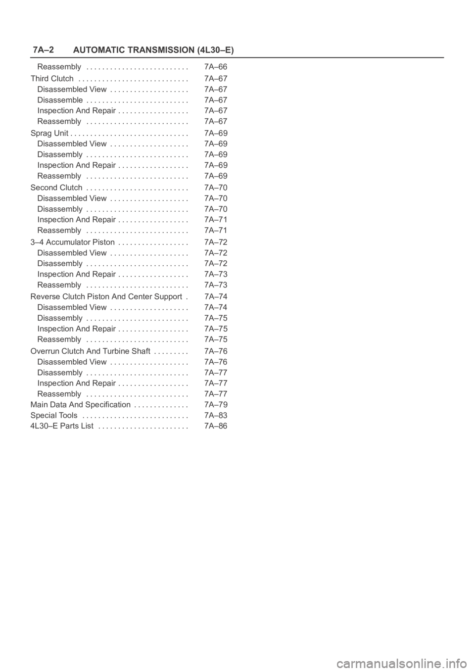
7A–2
AUTOMATIC TRANSMISSION (4L30–E)
Reassembly 7A–66. . . . . . . . . . . . . . . . . . . . . . . . . .
Third Clutch 7A–67. . . . . . . . . . . . . . . . . . . . . . . . . . . .
Disassembled View 7A–67. . . . . . . . . . . . . . . . . . . .
Disassemble 7A–67. . . . . . . . . . . . . . . . . . . . . . . . . .
Inspection And Repair 7A–67. . . . . . . . . . . . . . . . . .
Reassembly 7A–67. . . . . . . . . . . . . . . . . . . . . . . . . .
Sprag Unit 7A–69. . . . . . . . . . . . . . . . . . . . . . . . . . . . . .
Disassembled View 7A–69. . . . . . . . . . . . . . . . . . . .
Disassembly 7A–69. . . . . . . . . . . . . . . . . . . . . . . . . .
Inspection And Repair 7A–69. . . . . . . . . . . . . . . . . .
Reassembly 7A–69. . . . . . . . . . . . . . . . . . . . . . . . . .
Second Clutch 7A–70. . . . . . . . . . . . . . . . . . . . . . . . . .
Disassembled View 7A–70. . . . . . . . . . . . . . . . . . . .
Disassembly 7A–70. . . . . . . . . . . . . . . . . . . . . . . . . .
Inspection And Repair 7A–71. . . . . . . . . . . . . . . . . .
Reassembly 7A–71. . . . . . . . . . . . . . . . . . . . . . . . . .
3–4 Accumulator Piston 7A–72. . . . . . . . . . . . . . . . . .
Disassembled View 7A–72. . . . . . . . . . . . . . . . . . . .
Disassembly 7A–72. . . . . . . . . . . . . . . . . . . . . . . . . .
Inspection And Repair 7A–73. . . . . . . . . . . . . . . . . .
Reassembly 7A–73. . . . . . . . . . . . . . . . . . . . . . . . . .
Reverse Clutch Piston And Center Support 7A–74.
Disassembled View 7A–74. . . . . . . . . . . . . . . . . . . .
Disassembly 7A–75. . . . . . . . . . . . . . . . . . . . . . . . . .
Inspection And Repair 7A–75. . . . . . . . . . . . . . . . . .
Reassembly 7A–75. . . . . . . . . . . . . . . . . . . . . . . . . .
Overrun Clutch And Turbine Shaft 7A–76. . . . . . . . .
Disassembled View 7A–76. . . . . . . . . . . . . . . . . . . .
Disassembly 7A–77. . . . . . . . . . . . . . . . . . . . . . . . . .
Inspection And Repair 7A–77. . . . . . . . . . . . . . . . . .
Reassembly 7A–77. . . . . . . . . . . . . . . . . . . . . . . . . .
Main Data And Specification 7A–79. . . . . . . . . . . . . .
Special Tools 7A–83. . . . . . . . . . . . . . . . . . . . . . . . . . .
4L30–E Parts List 7A–86. . . . . . . . . . . . . . . . . . . . . . .
Page 5692 of 6000
7A–3 AUTOMATIC TRANSMISSION (4L30–E)
Service Precaution
WARNING: IF SO EQUIPPED WITH A
SUPPLEMENTAL RESTRAINT SYSTEM (SRS),
REFER TO THE SRS COMPONENT AND WIRING
LOCATION VIEW IN ORDER TO DETERMINE
WHETHER YOU ARE PERFORMING SERVICE ON OR
NEAR THE SRS COMPONENTS OR THE SRS
WIRING. WHEN YOU ARE PERFORMING SERVICE
ON OR NEAR THE SRS COMPONENTS OR THE SRS
WIRING, REFER TO THE SRS SERVICE
INFORMATION. FAILURE TO FOLLOW WARNINGS
COULD RESULT IN POSSIBLE AIR BAG
DEPLOYMENT, PERSONAL INJURY, OR
OTHERWISE UNNEEDED SRS SYSTEM REPAIRS.CAUTION: Always use the correct fastener in the
proper location. When you replace a fastener, use
ONLY the exact part number for that application.
ISUZU will call out those fasteners that require a
replacement after removal. ISUZU will also call out
the fasteners that require thread lockers or thread
sealant. UNLESS OTHERWISE SPECIFIED, do not
use supplemental coatings (Paints, greases, or other
corrosion inhibitors) on threaded fasteners or
fastener joint interfaces. Generally, such coatings
adversely affect the fastener torque and the joint
clamping force, and may damage the fastener. When
you install fasteners, use the correct tightening
sequence and specifications. Following these
instructions can help you avoid damage to parts and
systems.
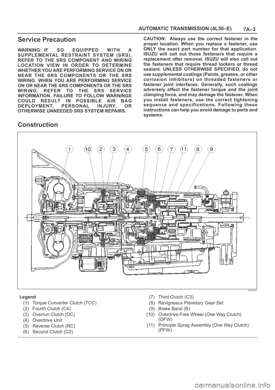
Construction
A07RS001
Legend
(1) Torque Converter Clutch (TCC)
(2) Fourth Clutch (C4)
(3) Overrun Clutch (OC)
(4) Overdrive Unit
(5) Reverse Clutch (RC)
(6) Second Clutch (C2)(7) Third Clutch (C3)
(8) Ravigneaux Planetary Gear Set
(9) Brake Band (B)
(10) Overdrive Free Wheel (One Way Clutch)
(OFW)
(11) Principle Sprag Assembly (One Way Clutch)
(PFW)
Page 5694 of 6000
7A–5 AUTOMATIC TRANSMISSION (4L30–E)
Normal Operation Of 2000 4L30–E
Tr a n s m i s s i o n
Torque Converter Clutch (TCC)
Application Conditions:
The TCC is normally applied in 2nd, 3rd and 4th gears
only when all of the following conditions exist:
— The engine coolant temperature is above 70
C
(158
F).
— The brake pedal is released.
— The shift pattern requests TCC apply.
Moreover, TCC is always applied in 2nd, 3rd and 4th
gears when the transmission oil temperature is above
135
C (275F).
This mode should be canceled at 125
C (257F).
ATF Warning Lamp
The ATF warning lamp will be constantly on (not flashing)
if the transmission oil temperature is above 145
C
(293
F).
The ATF warning lamp goes off again when the
transmission oil temperature is below 125
C (257F).
Special Shift Pattern When The Engine Is
Cold:
A special shift pattern is activated when the engine
coolant temperature is below 70
C (158F). (3–4 shifts,
for example, are delayed for small throttle openings and
will occur a few MPH higher.)
Diagnosis
Introduction
The systematic troubleshooting information covered by
this Section offers a practical and systematic approach to
diagnosing 4L30–E transmission, using information that
can be obtained from road tests, electrical diagnosis, oil
pressure checks or noise evaluation.
The key to correcting a complaint is to make use of all of
the available symptoms and logically letting them direct
you to the cause.
When dealing with automatic transmission complaints, it
is best to gather as many symptoms as possible before
making the decision to remove the transmission from the
vehicle.
Frequently, the correction of the complaint does not
require removal of the transmission from the vehicle.
Driver Information
To analyze the problem fill out a complete description of
the owner’s complaint.
Please draw a circle around the right information and
complete the following form. (The next page is an
example of a completed form). You can draw a circle
around many numbers if you are not sure.
Page 5702 of 6000
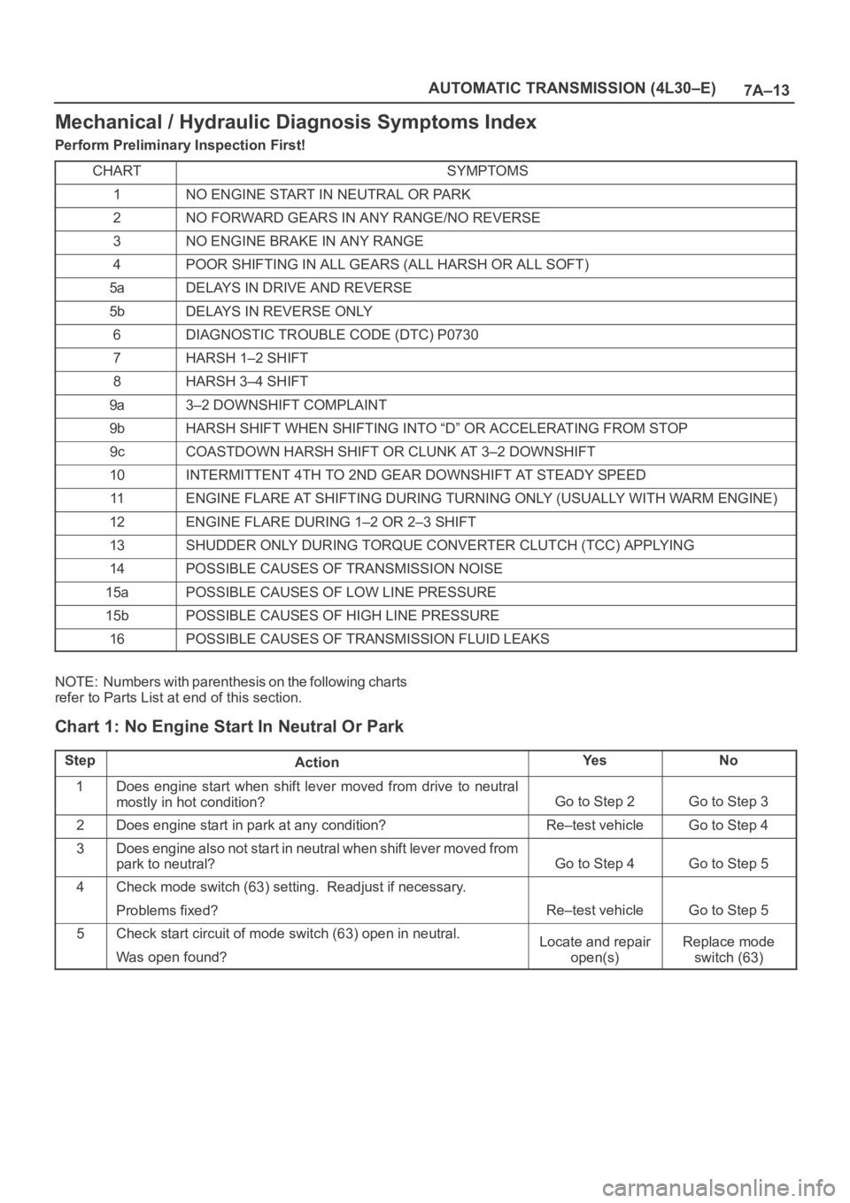
7A–13 AUTOMATIC TRANSMISSION (4L30–E)
Mechanical / Hydraulic Diagnosis Symptoms Index
Perform Preliminary Inspection First!
CHART
SYMPTOMS
1NO ENGINE START IN NEUTRAL OR PARK
2NO FORWARD GEARS IN ANY RANGE/NO REVERSE
3NO ENGINE BRAKE IN ANY RANGE
4POOR SHIFTING IN ALL GEARS (ALL HARSH OR ALL SOFT)
5aDELAYS IN DRIVE AND REVERSE
5bDELAYS IN REVERSE ONLY
6DIAGNOSTIC TROUBLE CODE (DTC) P0730
7HARSH 1–2 SHIFT
8HARSH 3–4 SHIFT
9a3–2 DOWNSHIFT COMPLAINT
9bHARSH SHIFT WHEN SHIFTING INTO “D” OR ACCELERATING FROM STOP
9cCOASTDOWN HARSH SHIFT OR CLUNK AT 3–2 DOWNSHIFT
10INTERMITTENT 4TH TO 2ND GEAR DOWNSHIFT AT STEADY SPEED
11ENGINE FLARE AT SHIFTING DURING TURNING ONLY (USUALLY WITH WARM ENGINE)
12ENGINE FLARE DURING 1–2 OR 2–3 SHIFT
13SHUDDER ONLY DURING TORQUE CONVERTER CLUTCH (TCC) APPLYING
14POSSIBLE CAUSES OF TRANSMISSION NOISE
15aPOSSIBLE CAUSES OF LOW LINE PRESSURE
15bPOSSIBLE CAUSES OF HIGH LINE PRESSURE
16POSSIBLE CAUSES OF TRANSMISSION FLUID LEAKS
NOTE: Numbers with parenthesis on the following charts
refer to Parts List at end of this section.
Chart 1: No Engine Start In Neutral Or Park
StepActionYe sNo
1Does engine start when shift lever moved from drive to neutral
mostly in hot condition?
Go to Step 2Go to Step 3
2Does engine start in park at any condition?Re–test vehicleGo to Step 4
3Does engine also not start in neutral when shift lever moved from
park to neutral?
Go to Step 4Go to Step 5
4Check mode switch (63) setting. Readjust if necessary.
Problems fixed?
Re–test vehicleGo to Step 5
5Check start circuit of mode switch (63) open in neutral.
Was open found?Locate and repair
open(s)Replace mode
switch (63)
Page 5703 of 6000
7A–14
AUTOMATIC TRANSMISSION (4L30–E)
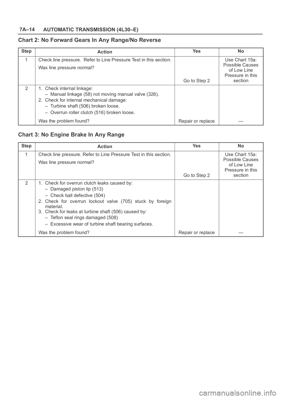
Chart 2: No Forward Gears In Any Range/No Reverse
StepActionYe sNo
1Check line pressure. Refer to Line Pressure Test in this section.
Was line pressure normal?
Go to Step 2
Use Chart 15a:
Possible Causes
of Low Line
Pressure in this
section
21. Check internal linkage:
– Manual linkage (58) not moving manual valve (326).
2. Check for internal mechanical damage:
– Turbine shaft (506) broken loose.
– Overrun roller clutch (516) broken loose.
Was the problem found?
Repair or replace—
Chart 3: No Engine Brake In Any Range
StepActionYe sNo
1Check line pressure. Refer to Line Pressure Test in this section.
Was line pressure normal?
Go to Step 2
Use Chart 15a:
Possible Causes
of Low Line
Pressure in this
section
21. Check for overrun clutch leaks caused by:
– Damaged piston lip (513)
– Check ball defective (504)
2. Check for overrun lockout valve (705) stuck by foreign
material.
3. Check for leaks at turbine shaft (506) caused by:
– Teflon seal rings damaged (508)
– Excessive wear of turbine shaft bearing surfaces.
Was the problem found?
Repair or replace—
Page 5704 of 6000
7A–15 AUTOMATIC TRANSMISSION (4L30–E)
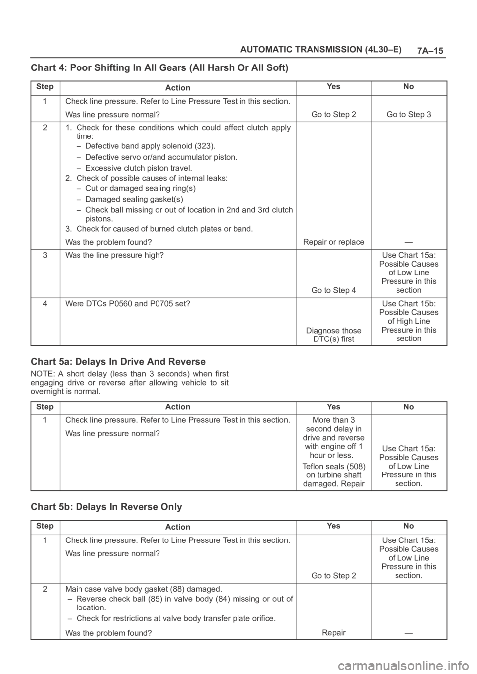
Chart 4: Poor Shifting In All Gears (All Harsh Or All Soft)
StepActionYe sNo
1Check line pressure. Refer to Line Pressure Test in this section.
Was line pressure normal?
Go to Step 2Go to Step 3
21. Check for these conditions which could affect clutch apply
time:
– Defective band apply solenoid (323).
– Defective servo or/and accumulator piston.
– Excessive clutch piston travel.
2. Check of possible causes of internal leaks:
– Cut or damaged sealing ring(s)
– Damaged sealing gasket(s)
– Check ball missing or out of location in 2nd and 3rd clutch
pistons.
3. Check for caused of burned clutch plates or band.
Was the problem found?
Repair or replace—
3Was the line pressure high?
Go to Step 4
Use Chart 15a:
Possible Causes
of Low Line
Pressure in this
section
4Were DTCs P0560 and P0705 set?
Diagnose those
DTC(s) first
Use Chart 15b:
Possible Causes
of High Line
Pressure in this
section
Chart 5a: Delays In Drive And Reverse
NOTE: A short delay (less than 3 seconds) when first
engaging drive or reverse after allowing vehicle to sit
overnight is normal.
Step
ActionYe sNo
1Check line pressure. Refer to Line Pressure Test in this section.
Was line pressure normal?More than 3
second delay in
drive and reverse
with engine off 1
hour or less.
Teflon seals (508)
on turbine shaft
damaged. Repair
Use Chart 15a:
Possible Causes
of Low Line
Pressure in this
section.
Chart 5b: Delays In Reverse Only
StepActionYe sNo
1Check line pressure. Refer to Line Pressure Test in this section.
Was line pressure normal?
Go to Step 2
Use Chart 15a:
Possible Causes
of Low Line
Pressure in this
section.
2Main case valve body gasket (88) damaged.
– Reverse check ball (85) in valve body (84) missing or out of
location.
– Check for restrictions at valve body transfer plate orifice.
Was the problem found?
Repair—
Page 5705 of 6000
7A–16
AUTOMATIC TRANSMISSION (4L30–E)
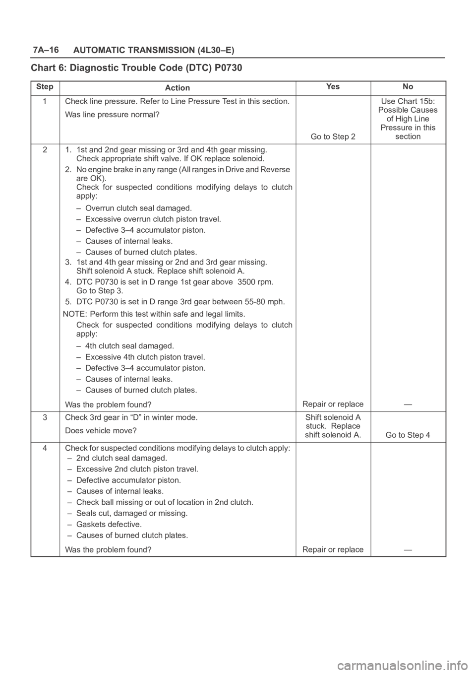
Chart 6: Diagnostic Trouble Code (DTC) P0730
StepActionYe sNo
1Check line pressure. Refer to Line Pressure Test in this section.
Was line pressure normal?
Go to Step 2
Use Chart 15b:
Possible Causes
of High Line
Pressure in this
section
21. 1st and 2nd gear missing or 3rd and 4th gear missing.
Check appropriate shift valve. If OK replace solenoid.
2. No engine brake in any range (All ranges in Drive and Reverse
are OK).
Check for suspected conditions modifying delays to clutch
apply:
– Overrun clutch seal damaged.
– Excessive overrun clutch piston travel.
– Defective 3–4 accumulator piston.
– Causes of internal leaks.
– Causes of burned clutch plates.
3. 1st and 4th gear missing or 2nd and 3rd gear missing.
Shift solenoid A stuck. Replace shift solenoid A.
4. DTC P0730 is set in D range 1st gear above 3500 rpm.
Go to Step 3.
5. DTC P0730 is set in D range 3rd gear between 55-80 mph.
NOTE: Perform this test within safe and legal limits.
Check for suspected conditions modifying delays to clutch
apply:
– 4th clutch seal damaged.
– Excessive 4th clutch piston travel.
– Defective 3–4 accumulator piston.
– Causes of internal leaks.
– Causes of burned clutch plates.
Was the problem found?
Repair or replace—
3Check 3rd gear in “D” in winter mode.
Does vehicle move?Shift solenoid A
stuck. Replace
shift solenoid A.
Go to Step 4
4Check for suspected conditions modifying delays to clutch apply:
– 2nd clutch seal damaged.
– Excessive 2nd clutch piston travel.
– Defective accumulator piston.
– Causes of internal leaks.
– Check ball missing or out of location in 2nd clutch.
– Seals cut, damaged or missing.
– Gaskets defective.
– Causes of burned clutch plates.
Was the problem found?
Repair or replace—