1998 OPEL FRONTERA clutch
[x] Cancel search: clutchPage 5006 of 6000
6E–349 ENGINE DRIVEABILITY AND EMISSIONS
Damage during re-gapping can happen if the gapping
tool is pushed against the center electrode or the
insulator around it, causing the insulator to crack.
When re-gapping a spark plug, make the adjustment
by bending only the ground side terminal, keeping the
tool clear of other parts.
”Heat shock” breakage in the lower insulator tip
generally occurs during several engine operating
conditions (high speeds or heavy loading) and may be
caused by over-advanced timing or low grade fuels.
Heat shock refers to a rapid increase in the tip
temperature that causes the insulator material to
crack.
Spark plugs with less than the recommended amount of
service can sometimes be cleaned and re-gapped , then
returned to service. However, if there is any doubt about
the serviceability of a spark plug, replace it. Spark plugs
with cracked or broken insulators should always be
replaced.
A/C Clutch Diagnosis
A/C Clutch Circuit Operation
A 12-volt signal is supplied to the A/C request input of the
PCM when the A/C is selected through the A/C control
switch.
The A/C compressor clutch relay is controlled through the
PCM. This allows the PCM to modify the idle air control
position prior to the A/C clutch engagement for better idle
quality. If the engine operating conditions are within their
specified calibrated acceptable ranges, the PCM will
enable the A/C compressor relay. This is done by
providing a ground path for the A/C relay coil within the
PCM. When the A/C compressor relay is enabled,
battery voltage is supplied to the compressor clutch coil.
The PCM will enable the A/C compressor clutch
whenever the engine is running and the A/C has been
requested. The PCM will not enable the A/C compressor
clutch if any of the following conditions are met:
The throttle is greater than 90%.
The engine speed is greater than 6315 RPM.
The ECT is greater than 119C (246F).
The IAT is less than 5C (41F).
The throttle is more than 80% open.
A/C Clutch Circuit Purpose
The A/C compressor operation is controlled by the
powertrain control module (PCM) for the following
reasons:
It improvises idle quality during compressor clutch
engagement.
It improvises wide open throttle (WOT) performance.
It provides A/C compressor protection from operation
with incorrect refrigerant pressures.
The A/C electrical system consists of the following
components:
The A/C control head.
The A/C refrigerant pressure switches.
The A/C compressor clutch.
The A/C compressor clutch relay.
The PCM.
A/C Request Signal
This signal tells the PCM when the A/C mode is selected
at the A/C control head. The PCM uses this to adjust the
idle speed before turning on the A/C clutch. The A/C
compressor will be inoperative if this signal is not
available to the PCM.
Refer to
A/C Clutch Circuit Diagnosis for A/C wiring
diagrams and diagnosis for A/C electrical system.
General Description (Exhaust Gas
Recirculation (EGR) System)
EGR Purpose
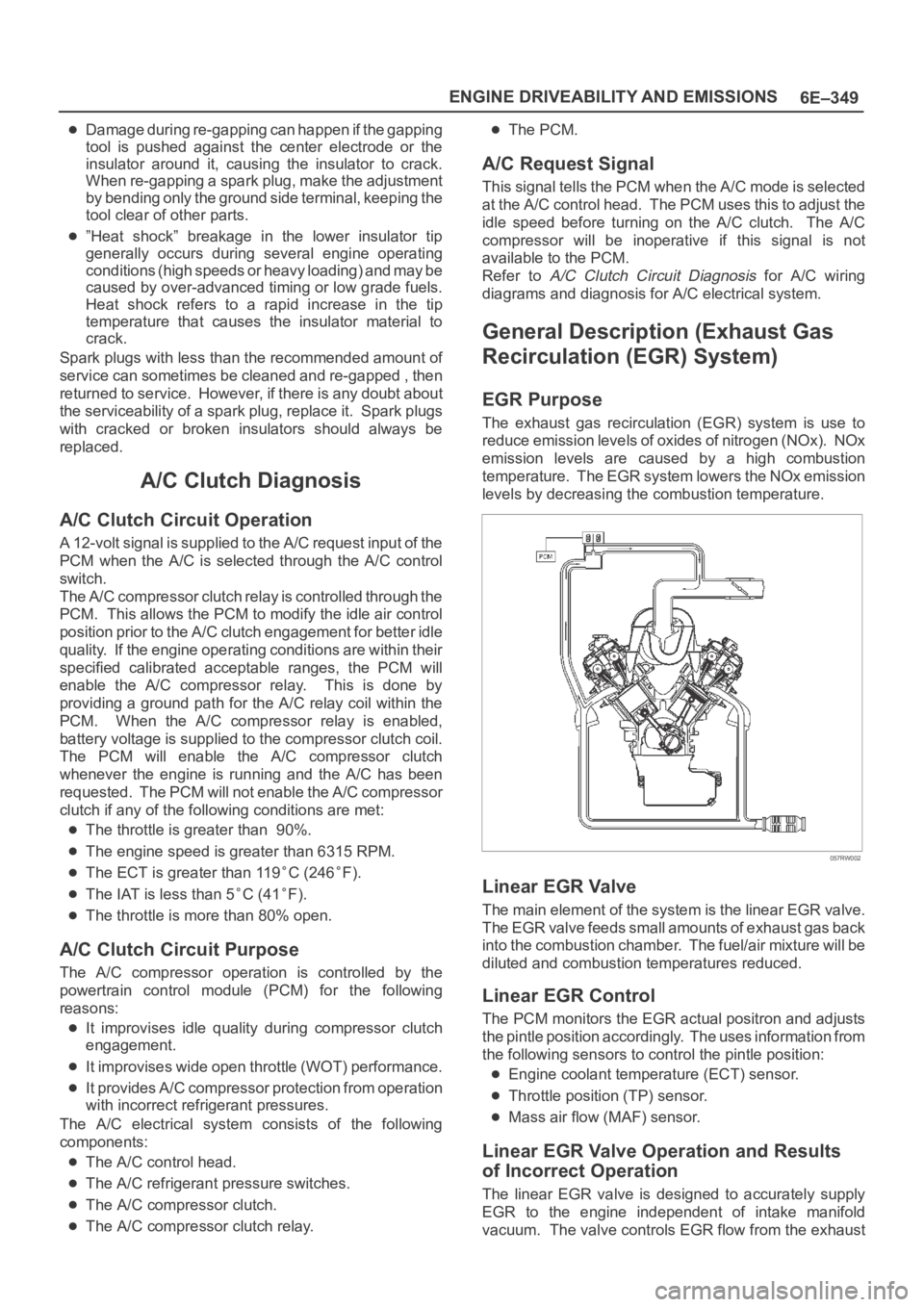
The exhaust gas recirculation (EGR) system is use to
reduce emission levels of oxides of nitrogen (NOx). NOx
emission levels are caused by a high combustion
temperature. The EGR system lowers the NOx emission
levels by decreasing the combustion temperature.
057RW002
Linear EGR Valve
The main element of the system is the linear EGR valve.
The EGR valve feeds small amounts of exhaust gas back
into the combustion chamber. The fuel/air mixture will be
diluted and combustion temperatures reduced.
Linear EGR Control
The PCM monitors the EGR actual positron and adjusts
the pintle position accordingly. The uses information from
the following sensors to control the pintle position:
Engine coolant temperature (ECT) sensor.
Throttle position (TP) sensor.
Mass air flow (MAF) sensor.
Linear EGR Valve Operation and Results
of Incorrect Operation
The linear EGR valve is designed to accurately supply
EGR to the engine independent of intake manifold
vacuum. The valve controls EGR flow from the exhaust
Page 5299 of 6000
6A – 26 ENGINE MECHANICAL
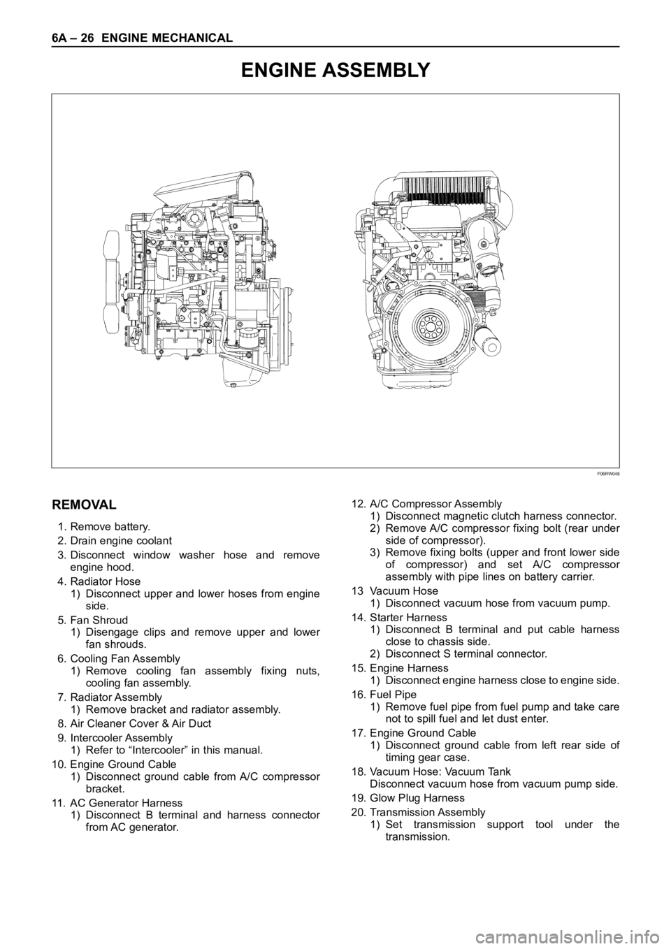
ENGINE ASSEMBLY
F06RW048
REMOVAL
1. Remove battery.
2. Drain engine coolant
3. Disconnect window washer hose and remove
engine hood.
4. Radiator Hose
1) Disconnect upper and lower hoses from engine
side.
5. Fan Shroud
1) Disengage clips and remove upper and lower
fan shrouds.
6. Cooling Fan Assembly
1) Remove cooling fan assembly fixing nuts,
cooling fan assembly.
7. Radiator Assembly
1) Remove bracket and radiator assembly.
8. Air Cleaner Cover & Air Duct
9. Intercooler Assembly
1) Refer to “Intercooler” in this manual.
10. Engine Ground Cable
1) Disconnect ground cable from A/C compressor
bracket.
11. AC Generator Harness
1) Disconnect B terminal and harness connector
from AC generator.12. A/C Compressor Assembly
1) Disconnect magnetic clutch harness connector.
2) Remove A/C compressor fixing bolt (rear under
side of compressor).
3) Remove fixing bolts (upper and front lower side
of compressor) and set A/C compressor
assembly with pipe lines on battery carrier.
13 Vacuum Hose
1) Disconnect vacuum hose from vacuum pump.
14. Starter Harness
1) Disconnect B terminal and put cable harness
close to chassis side.
2) Disconnect S terminal connector.
15. Engine Harness
1) Disconnect engine harness close to engine side.
16. Fuel Pipe
1) Remove fuel pipe from fuel pump and take care
not to spill fuel and let dust enter.
17. Engine Ground Cable
1) Disconnect ground cable from left rear side of
timing gear case.
18. Vacuum Hose: Vacuum Tank
Disconnect vacuum hose from vacuum pump side.
19. Glow Plug Harness
20. Transmission Assembly
1) Set transmission support tool under the
transmission.
Page 5375 of 6000
6B – 6 ENGINE COOLING
REMOVAL
1. Drain coolant.
2. AC Generator Drive Belt
1) Loosen AC Generator mounting bolt, adjust
plate lock bolt, and remove the drive belt.
3. Cooling Fan Assembly
1) Remove lock nut and take out cooling fan
assembly with cooling fan clutch.
4. Water Pump Assembly
INSPECTION
Make necessary repair and parts replacement if
excessive wear or damage is found during inspection.
Should any of the following problems occur, the entire
water pump assembly must be replaced.
1) Cracks in the water pump body
2) Coolant leakage from the seal unit
3) Play or abnormal noise in the bearing
4) Cracks or corrosion in the impeller
INSTALLATION
1. Gasket
1) Set gasket to gear case.
2. Water Pump Assembly
1) Install water pump assembly, and tighten to
specified torque.
Torque: 20 Nꞏm (2.0 kgꞏm/14.5 lb ft)3. Cooling Fan Assembly
1) Install cooling fan assembly, and tighten to
specified torque.
Torque: 8 Nꞏm (0.8 kgꞏm/5.8 lb ft)
4. AC Generator Drive Belt
1) Install AC Generator drive belt and adjust belt
tension.
Torque: 40 Nꞏm (4.1 kgꞏm/29.7 lb ft)
For ACG to bracket
20 Nꞏm (2.0 kgꞏm/14.5 lb ft)
For ACG to adjust plate
5. Fill coolant to specified capacity.
12
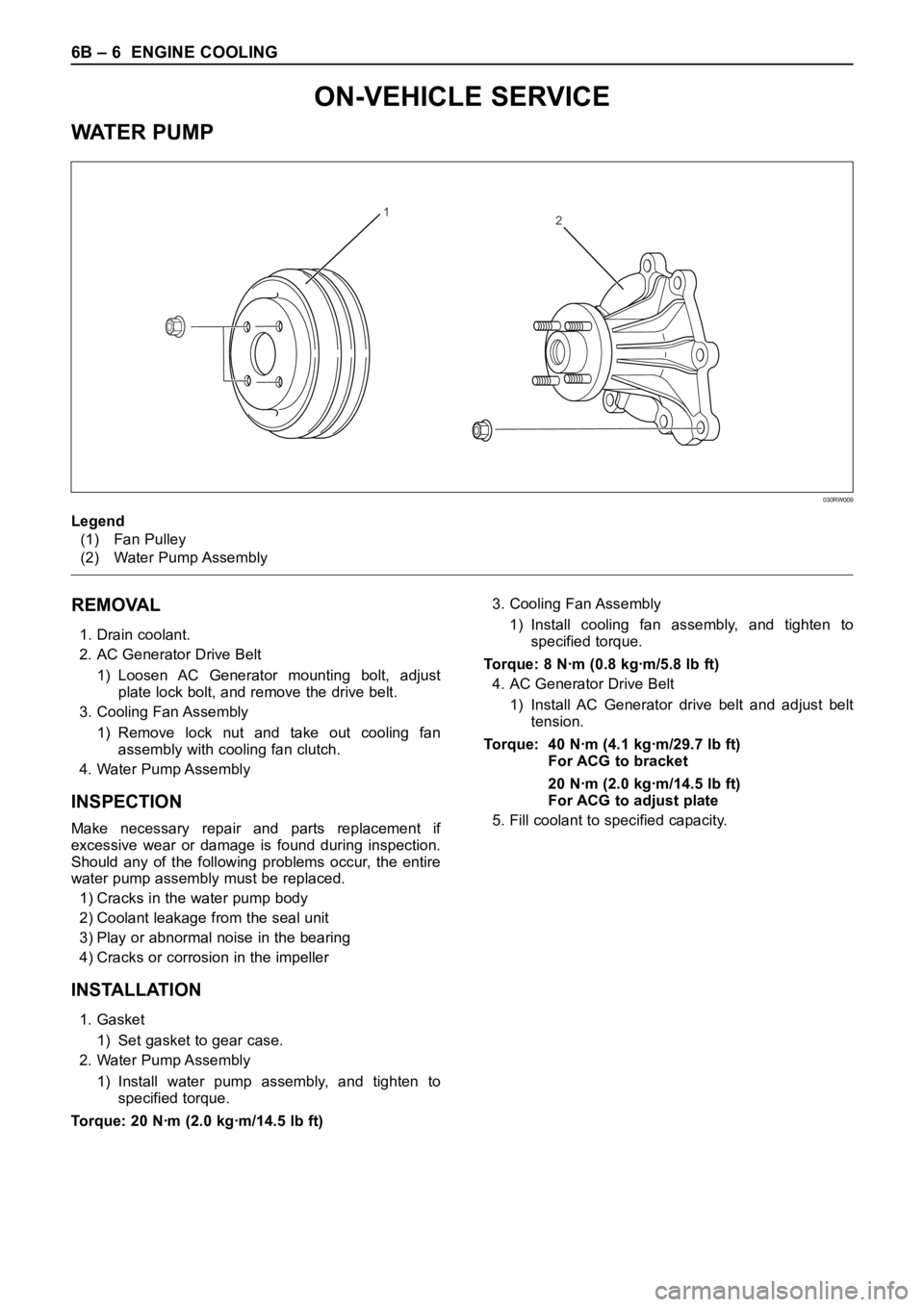
Legend
(1) Fan Pulley
(2) Water Pump Assembly
030RW009
ON-VEHICLE SERVICE
WAT E R P U M P
Page 5408 of 6000
ENGINE ELECTRICAL 6D – 5
STARTING SYTEM
GENERAL DESCRIPTION
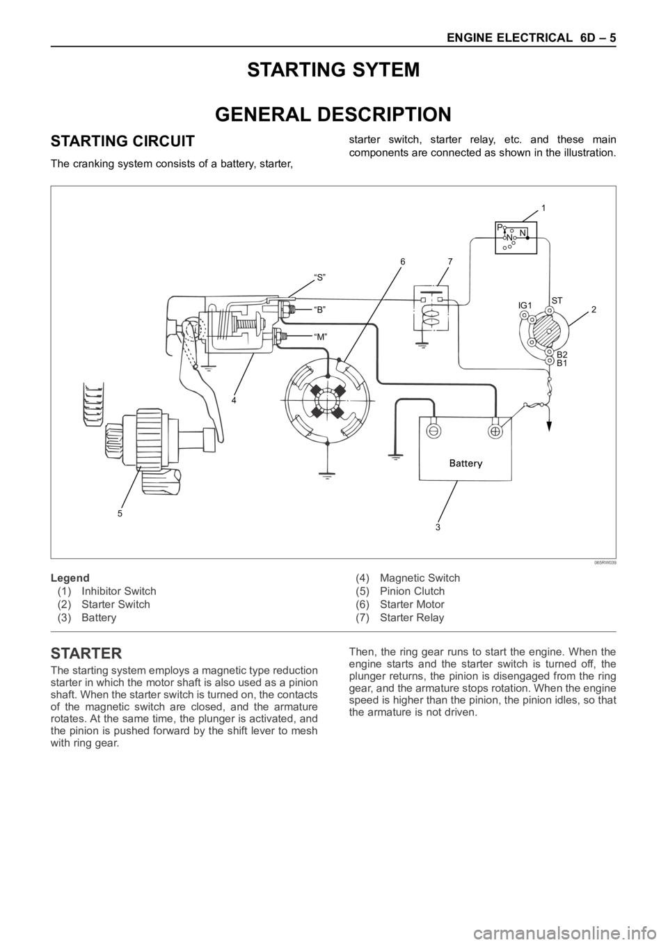
STARTING CIRCUIT
The cranking system consists of a battery, starter, starter switch, starter relay, etc. and these main
components are connected as shown in the illustration.
“S”
“B”
“M”
5
4
32 IG1ST
B2
B1
1
76
P
NN
Legend
(1) Inhibitor Switch
(2) Starter Switch
(3) Battery(4) Magnetic Switch
(5) Pinion Clutch
(6) Starter Motor
(7) Starter Relay
065RW039
STARTER
The starting system employs a magnetic type reduction
starter in which the motor shaft is also used as a pinion
shaft. When the starter switch is turned on, the contacts
of the magnetic switch are closed, and the armature
rotates. At the same time, the plunger is activated, and
the pinion is pushed forward by the shift lever to mesh
with ring gear.Then, the ring gear runs to start the engine. When the
engine starts and the starter switch is turned off, the
plunger returns, the pinion is disengaged from the ring
gear, and the armature stops rotation. When the engine
speed is higher than the pinion, the pinion idles, so that
the armature is not driven.
Page 5410 of 6000
ENGINE ELECTRICAL 6D – 7
ON-VEHICLE SERVICE
STARTER
REMOVAL
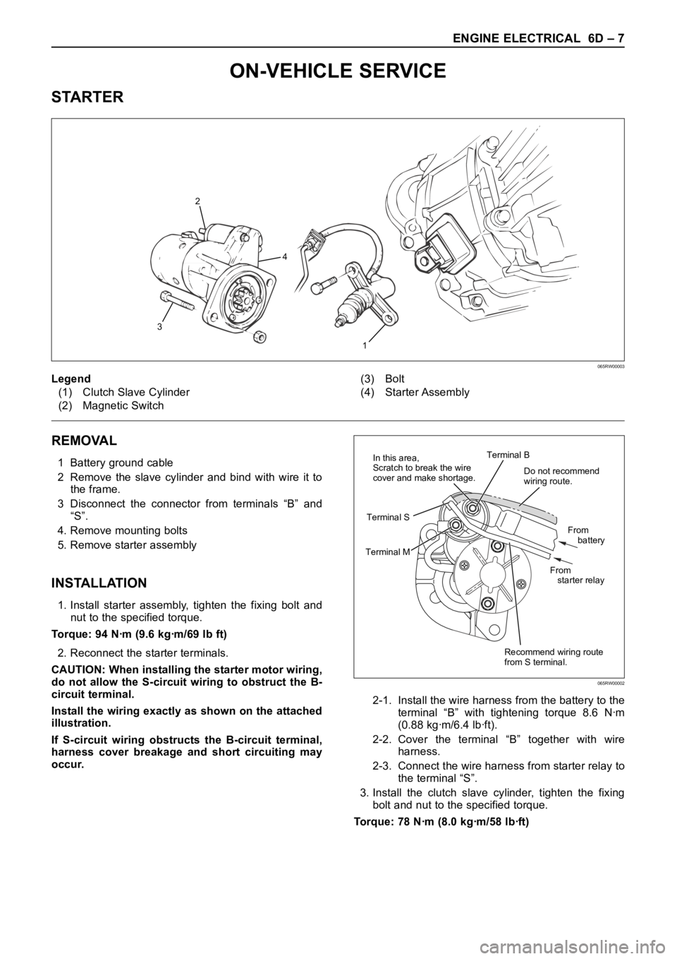
1 Battery ground cable
2 Remove the slave cylinder and bind with wire it to
the frame.
3 Disconnect the connector from terminals “B” and
“S”.
4. Remove mounting bolts
5. Remove starter assembly
INSTALLATION
1. Install starter assembly, tighten the fixing bolt and
nut to the specified torque.
Torque: 94 Nꞏm (9.6 kgꞏm/69 lb ft)
2. Reconnect the starter terminals.
CAUTION: When installing the starter motor wiring,
do not allow the S-circuit wiring to obstruct the B-
circuit terminal.
Install the wiring exactly as shown on the attached
illustration.
If S-circuit wiring obstructs the B-circuit terminal,
harness cover breakage and short circuiting may
occur.2-1. Install the wire harness from the battery to the
terminal “B” with tightening torque 8.6 Nꞏm
(0.88 kgꞏm/6.4 lbꞏft).
2-2. Cover the terminal “B” together with wire
harness.
2-3. Connect the wire harness from starter relay to
the terminal “S”.
3. Install the clutch slave cylinder, tighten the fixing
bolt and nut to the specified torque.
Torque: 78 Nꞏm (8.0 kgꞏm/58 lbꞏft)
1
32
4
Legend
(1) Clutch Slave Cylinder
(2) Magnetic Switch(3) Bolt
(4) Starter Assembly
065RW00003
Do not recommend
wiring route.
Recommend wiring route
from S terminal.From
battery
From
starter relay Terminal B
Terminal MTerminal SIn this area,
Scratch to break the wire
cover and make shortage.
065RW00002
Page 5411 of 6000
6D – 8 ENGINE ELECTRICAL
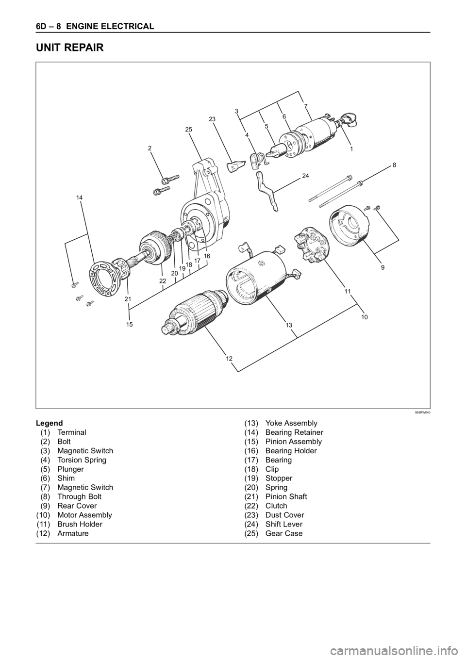
UNIT REPAIR
8
241 3
23
25
2
14
15 21222019181716
109
11
13
127
6
5
4
Legend
(1) Terminal
(2) Bolt
(3) Magnetic Switch
(4) Torsion Spring
(5) Plunger
(6) Shim
(7) Magnetic Switch
(8) Through Bolt
(9) Rear Cover
(10) Motor Assembly
(11) Brush Holder
(12) Armature(13) Yoke Assembly
(14) Bearing Retainer
(15) Pinion Assembly
(16) Bearing Holder
(17) Bearing
(18) Clip
(19) Stopper
(20) Spring
(21) Pinion Shaft
(22) Clutch
(23) Dust Cover
(24) Shift Lever
(25) Gear Case
065RW040
Page 5412 of 6000
ENGINE ELECTRICAL 6D – 9
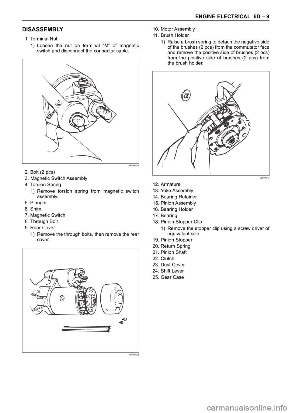
DISASSEMBLY
1. Terminal Nut
1) Loosen the nut on terminal “M” of magnetic
switch and disconnect the connector cable.
2. Bolt (2 pcs)
3. Magnetic Switch Assembly
4. Torsion Spring
1) Remove torsion spring from magnetic switch
assembly.
5. Plunger
6. Shim
7. Magnetic Switch
8. Through Bolt
9. Rear Cover
1) Remove the through bolts, then remove the rear
cover.10. Motor Assembly
11. Brush Holder
1) Raise a brush spring to detach the negative side
of the brushes (2 pcs) from the commutator face
and remove the positive side of brushes (2 pcs)
from the positive side of brushes (2 pcs) from
the brush holder.
12. Armature
13. Yoke Assembly
14. Bearing Retainer
15. Pinion Assembly
16. Bearing Holder
17. Bearing
18. Pinion Stopper Clip
1) Remove the stopper clip using a screw driver of
equivalent size.
19. Pinion Stopper
20. Return Spring
21. Pinion Shaft
22. Clutch
23. Dust Cover
24. Shift Lever
25. Gear Case
065RW044
065RW043
065RW042
Page 5435 of 6000
6E–6
4JX1–TC ENGINE DRIVEABILITY AND EMISSIONS
Removal Procedure 6E–212. . . . . . . . . . . . . . . . . . . .
Installation Procedure 6E–212. . . . . . . . . . . . . . . . . .
Fuel Filter Cap 6E–213. . . . . . . . . . . . . . . . . . . . . . . . . .
General Description 6E–213. . . . . . . . . . . . . . . . . . . .
Inspection Procedure 6E–213. . . . . . . . . . . . . . . . . .
Fuel Filter 6E–213. . . . . . . . . . . . . . . . . . . . . . . . . . . . . .
Removal and Installation Procedure 6E–213. . . . . .
Fuel Gauge Unit 6E–213. . . . . . . . . . . . . . . . . . . . . . . .
Removal Procedure 6E–213. . . . . . . . . . . . . . . . . . . .
Installation Procedure 6E–214. . . . . . . . . . . . . . . . . .
Fuel Injectors 6E–214. . . . . . . . . . . . . . . . . . . . . . . . . . .
Removal and Installation Procedure 6E–214. . . . . .
Fuel Temperature Sensor 6E–214. . . . . . . . . . . . . . . .
Removal Procedure 6E–214. . . . . . . . . . . . . . . . . . . .
Installation Procedure 6E–215. . . . . . . . . . . . . . . . . .
Rail Pressure (RP) Sensor 6E–216. . . . . . . . . . . . . . .
Removal Procedure 6E–216. . . . . . . . . . . . . . . . . . . .
Installation Procedure 6E–216. . . . . . . . . . . . . . . . . .
Fuel Tank 6E–216. . . . . . . . . . . . . . . . . . . . . . . . . . . . . .
Removal Procedure 6E–216. . . . . . . . . . . . . . . . . . . .
Throttle Body (TB) 6E–217. . . . . . . . . . . . . . . . . . . . . . .
Removal Procedure 6E–217. . . . . . . . . . . . . . . . . . . .
Installation Procedure 6E–217. . . . . . . . . . . . . . . . . .
Air Conditioning (A/C) Relay 6E–217. . . . . . . . . . . . . .
Removal Procedure 6E–217. . . . . . . . . . . . . . . . . . . .
Installation Procedure 6E–217. . . . . . . . . . . . . . . . . .
Exhaust Gas Recirculation (EGR) Vacuum
Switch Valve (VSV) 6E–217. . . . . . . . . . . . . . . . . . . . .
Removal Procedure 6E–217. . . . . . . . . . . . . . . . . . . .
Installation Procedure 6E–218. . . . . . . . . . . . . . . . . .
Electronic Vacuum Regurating Valve (EVRV) 6E–219
Removal Procedure 6E–219. . . . . . . . . . . . . . . . . . . .
Installation Procedure 6E–220. . . . . . . . . . . . . . . . . .
Wiring and Connectors 6E–220. . . . . . . . . . . . . . . . . . .
Wiring Harness Service 6E–220. . . . . . . . . . . . . . . .
Connectors and Terminals 6E–220. . . . . . . . . . . . . .
Wire Harness Repair: Twisted Shielded
Cable 6E–220. . . . . . . . . . . . . . . . . . . . . . . . . . . . . . . . .
Removal Procedure 6E–220. . . . . . . . . . . . . . . . . . . .
Installation Procedure 6E–221. . . . . . . . . . . . . . . . . .
Twisted Leads 6E–221. . . . . . . . . . . . . . . . . . . . . . . . . .
Removal Procedure 6E–221. . . . . . . . . . . . . . . . . . . .
Installation Procedure 6E–222. . . . . . . . . . . . . . . . . .
Weather-Pack Connector 6E–223. . . . . . . . . . . . . . . . .
Tools Required 6E–223. . . . . . . . . . . . . . . . . . . . . . . .
Removal Procedure 6E–223. . . . . . . . . . . . . . . . . . . . Installation Procedure 6E–223. . . . . . . . . . . . . . . . . .
Com-Pack III 6E–224. . . . . . . . . . . . . . . . . . . . . . . . . . .
General Information 6E–224. . . . . . . . . . . . . . . . . . . .
Metri-Pack 6E–224. . . . . . . . . . . . . . . . . . . . . . . . . . . . .
Tools Required 6E–224. . . . . . . . . . . . . . . . . . . . . . . .
Removal Procedure 6E–224
. . . . . . . . . . . . . . . . . . . .
Installation Procedure 6E–224. . . . . . . . . . . . . . . . . .
General Description
(ECM and Sensors) 6E–225. . . . . . . . . . . . . . . . . . . . .
57X Reference ECM Input 6E–225. . . . . . . . . . . . . .
A/C Request Signal 6E–225. . . . . . . . . . . . . . . . . . . .
Crankshaft Position (CKP) Sensor 6E–225. . . . . . .
Camshaft Position (CMP) Sensor and
Signal 6E–225. . . . . . . . . . . . . . . . . . . . . . . . . . . . . . .
Engine Coolant Temperature (ECT) Sensor 6E–225
Electrically Erasable Programmable Read
Only Memory (EEPROM) 6E–225. . . . . . . . . . . . . .
Intake Air Temperature (IAT) Sensor 6E–225. . . . .
Manifold Absolute Pressure (MAP) Sensor 6E–226
Engine Control Module (ECM) 6E–226. . . . . . . . . . .
ECM Function 6E–226. . . . . . . . . . . . . . . . . . . . . . . . .
ECM Components 6E–226. . . . . . . . . . . . . . . . . . . . .
ECM Voltage Description 6E–226. . . . . . . . . . . . . . .
ECM Input/Outputs 6E–226. . . . . . . . . . . . . . . . . . . .
ECM Service Precautions 6E–227. . . . . . . . . . . . . .
Intake Throttle Position (ITP) Sensor 6E–227. . . . .
Transmission Range Switch 6E–227. . . . . . . . . . . . .
Accelerator Position Sensor (AP) 6E–227. . . . . . . .
Aftermarket Electrical and Vacuum
Equipment 6E–227. . . . . . . . . . . . . . . . . . . . . . . . . . .
Electrostatic Discharge Damage 6E–227. . . . . . . . .
General Description (Air Induction) 6E–228. . . . . . . .
Air Induction System 6E–228. . . . . . . . . . . . . . . . . . .
General Description (Fuel Metering) 6E–228. . . . . . .
Deceleration Mode 6E–228. . . . . . . . . . . . . . . . . . . .
Fuel Injector 6E–228. . . . . . . . . . . . . . . . . . . . . . . . . .
Fuel Metering System Components 6E–228. . . . . .
A/C Clutch Diagnosis 6E–228. . . . . . . . . . . . . . . . . . . .
A/C Request Signal 6E–228. . . . . . . . . . . . . . . . . . . .
General Description Exhaust Gas
Recirculation (EGR) System 6E–228. . . . . . . . . . . . .
EGR Purpose 6E–228. . . . . . . . . . . . . . . . . . . . . . . . .
Fuse and Relay Panel
(Underhood Electrical Center) RHD 6E–229. . . . . . .
Fuse and Relay Panel
(Underhood Electrical Center) LHD 6E–230. . . . . . .