1998 OPEL FRONTERA clutch
[x] Cancel search: clutchPage 4388 of 6000
5A–38
BRAKE CONTROL SYSTEM
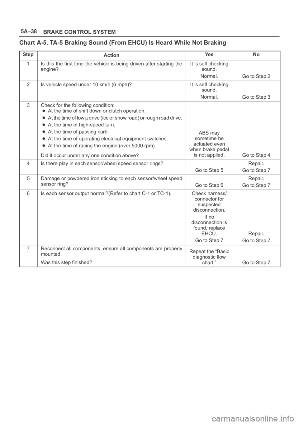
Chart A-5, TA-5 Braking Sound (From EHCU) Is Heard While Not Braking
StepActionYe sNo
1Is this the first time the vehicle is being driven after starting the
engine?It is self checking
sound.
Normal.
Go to Step 2
2Is vehicle speed under 10 km/h (6 mph)?It is self checking
sound.
Normal.
Go to Step 3
3Check for the following condition:
At the time of shift down or clutch operation.
A t t h e t i m e o f l o w drive (ice or snow road) or rough road drive.
At the time of high-speed turn.
At the time of passing curb.
At the time of operating electrical equipment switches.
At the time of racing the engine (over 5000 rpm).
Did it occur under any one condition above?
ABS may
sometime be
actuated even
when brake pedal
is not applied.
Go to Step 4
4Is there play in each sensor/wheel speed sensor rings?
Go to Step 5
Repair.
Go to Step 7
5Damage or powdered iron sticking to each sensor/wheel speed
sensor ring?
Go to Step 6
Repair.
Go to Step 7
6Is each sensor output normal?(Refer to chart C-1 or TC-1).Check harness/
connector for
suspected
disconnection.
If no
disconnection is
found, replace
EHCU.
Go to Step 7
Repair.
Go to Step 7
7Reconnect all components, ensure all components are properly
mounted.
Was this step finished?Repeat the “Basic
diagnostic flow
chart.”
Go to Step 7
Page 4507 of 6000
6A–11
ENGINE MECHANICAL
Condition CorrectionPossible cause
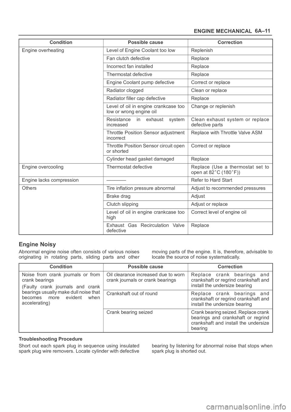
Engine overheatingLevel of Engine Coolant too lowReplenish
Fan clutch defectiveReplace
Incorrect fan installedReplace
Thermostat defectiveReplace
Engine Coolant pump defectiveCorrect or replace
Radiator cloggedClean or replace
Radiator filler cap defectiveReplace
Level of oil in engine crankcase too
low or wrong engine oilChange or replenish
Resistance in exhaust system
increasedClean exhaust system or replace
defective parts
Throttle Position Sensor adjustment
incorrectReplace with Throttle Valve ASM
Throttle Position Sensor circuit open
or shortedCorrect or replace
Cylinder head gasket damagedReplace
Engine overcoolingThermostat defectiveReplace (Use a thermostat set to
open at 82
C (180F))
Engine lacks compression————Refer to Hard Start
OthersTire inflation pressure abnormalAdjust to recommended pressures
Brake dragAdjust
Clutch slippingAdjust or replace
Level of oil in engine crankcase too
highCorrect level of engine oil
Exhaust Gas Recirculation Valve
defectiveReplace
Engine Noisy
Abnormal engine noise often consists of various noises
originating in rotating parts, sliding parts and othermoving parts of the engine. It is, therefore, advisable to
locate the source of noise systematically.
Condition
Possible causeCorrection
Noise from crank journals or from
crank bearings
(Faulty crank journals and crankOil clearance increased due to worn
crank journals or crank bearingsReplace crank bearings and
crankshaft or regrind crankshaft and
install the undersize bearing
yj
bearings usually make dull noise that
becomes more evident when
accelerating)Crankshaft out of roundReplace crank bearings and
crankshaft or regrind crankshaft and
install the undersize bearing
Crank bearing seizedCrank bearing seized. Replace crank
bearings and crankshaft or regrind
crankshaft and install the undersize
bearing
Troubleshooting Procedure
Short out each spark plug in sequence using insulated
spark plug wire removers. Locate cylinder with defectivebearing by listening for abnormal noise that stops when
spark plug is shorted out.
Page 4508 of 6000
6A–12
ENGINE MECHANICAL
ConditionPossible causeCorrection
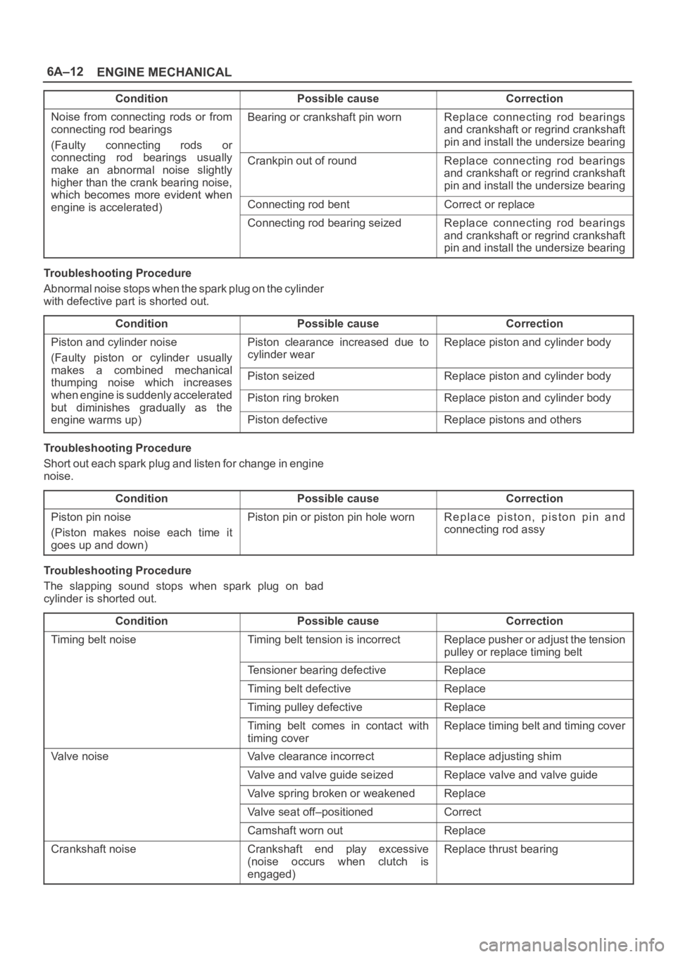
Noise from connecting rods or from
connecting rod bearings
(Faulty connecting rods orBearing or crankshaft pin wornReplace connecting rod bearings
and crankshaft or regrind crankshaft
pin and install the undersize bearing
yg
connecting rod bearings usually
make an abnormal noise slightly
higher than the crank bearing noise,
which becomes more evident when
Crankpin out of roundReplace connecting rod bearings
and crankshaft or regrind crankshaft
pin and install the undersize bearing
which becomes more evident when
engine is accelerated)Connecting rod bentCorrect or replaceg)
Connecting rod bearing seizedReplace connecting rod bearings
and crankshaft or regrind crankshaft
pin and install the undersize bearing
Troubleshooting Procedure
Abnormal noise stops when the spark plug on the cylinder
with defective part is shorted out.
Condition
Possible causeCorrection
Piston and cylinder noise
(Faulty piston or cylinder usually
kbidhil
Piston clearance increased due to
cylinder wearReplace piston and cylinder body
makes a combined mechanical
thumping noise which increasesPiston seizedReplace piston and cylinder bodyg
when engine is suddenly accelerated
but diminishes
gradually as thePiston ring brokenReplace piston and cylinder bodybut diminishes gradually as the
engine warms up)Piston defectiveReplace pistons and others
Troubleshooting Procedure
Short out each spark plug and listen for change in engine
noise.
Condition
Possible causeCorrection
Piston pin noise
(Piston makes noise each time it
goes up and down)Piston pin or piston pin hole wornReplace piston, piston pin and
connecting rod assy
Troubleshooting Procedure
The slapping sound stops when spark plug on bad
cylinder is shorted out.
Condition
Possible causeCorrection
Timing belt noiseTiming belt tension is incorrectReplace pusher or adjust the tension
pulley or replace timing belt
Tensioner bearing defectiveReplace
Timing belt defectiveReplace
Timing pulley defectiveReplace
Timing belt comes in contact with
timing coverReplace timing belt and timing cover
Valve noiseValve clearance incorrectReplace adjusting shim
Valve and valve guide seizedReplace valve and valve guide
Valve spring broken or weakenedReplace
Valve seat off–positionedCorrect
Camshaft worn outReplace
Crankshaft noiseCrankshaft end play excessive
(noise occurs when clutch is
engaged)Replace thrust bearing
Page 4511 of 6000
6A–15
ENGINE MECHANICAL
Condition CorrectionPossible cause
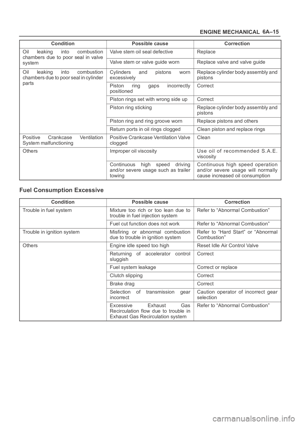
Oil leaking into combustion
chambers due topoor seal in valve
Valve stem oil seal defectiveReplace
chambers due to oor seal in valve
systemValve stem or valve guide wornReplace valve and valve guide
Oil leaking into combustion
chambers due to poor seal in cylinder
t
Cylinders and pistons worn
excessivelyReplace cylinder body assembly and
pistons
partsPiston ring gaps incorrectly
positionedCorrect
Piston rings set with wrong side upCorrect
Piston ring stickingReplace cylinder body assembly and
pistons
Piston ring and ring groove wornReplace pistons and others
Return ports in oil rings cloggedClean piston and replace rings
Positive Crankcase Ventilation
System malfunctioningPositive Crankcase Ventilation Valve
cloggedClean
OthersImproper oil viscosityUse oil of recommended S.A.E.
viscosity
Continuous high speed driving
and/or severe usage such as trailer
towingContinuous high speed operation
and/or severe usage will normally
cause increased oil consumption
Fuel Consumption Excessive
ConditionPossible causeCorrection
Trouble in fuel systemMixture too rich or too lean due to
trouble in fuel injection systemRefer to “Abnormal Combustion”
Fuel cut function does not workRefer to “Abnormal Combustion”
Trouble in ignition systemMisfiring or abnormal combustion
due to trouble in ignition systemRefer to “Hard Start” or “Abnormal
Combustion”
OthersEngine idle speed too highReset Idle Air Control Valve
Returning of accelerator control
sluggishCorrect
Fuel system leakageCorrect or replace
Clutch slippingCorrect
Brake dragCorrect
Selection of transmission gear
incorrectCaution operator of incorrect gear
selection
Excessive Exhaust Gas
Recirculation flow due to trouble in
Exhaust Gas Recirculation systemRefer to “Abnormal Combustion”
Page 4514 of 6000
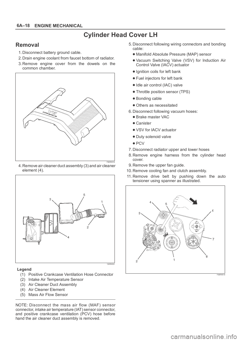
6A–18
ENGINE MECHANICAL
Cylinder Head Cover LH
Removal
1. Disconnect battery ground cable.
2. Drain engine coolant from faucet bottom of radiator.
3. Remove engine cover from the dowels on the
common chamber.
F06RW018
4. Remove air cleaner duct assembly (3) and air cleaner
element (4).
130RW001
Legend
(1) Positive Crankcase Ventilation Hose Connector
(2) Intake Air Temperature Sensor
(3) Air Cleaner Duct Assembly
(4) Air Cleaner Element
(5) Mass Air Flow Sensor
NOTE: Disconnect the mass air flow (MAF) sensor
connector, intake air temperature (IAT) sensor connector,
and positive crankcase ventilation (PCV) hose before
hand the air cleaner duct assembly is removed.5. Disconnect following wiring connectors and bonding
cable:
Manifold Absolute Pressure (MAP) sensor
Vacuum Switching Valve (VSV) for Induction Air
Control Valve (IACV) actuator
Ignition coils for left bank
Fuel injectors for left bank
Idle air control (IAC) valve
Throttle position sensor (TPS)
Bonding cable
Others as necessitated
6. Disconnect following vacuum hoses:
Brake master VAC
Canister
VSV for IACV actuator
Duty solenoid valve
PCV
7. Disconnect radiator upper and lower hoses
8. Remove engine harness from the cylinder head
cover.
9. Remove the upper fan guide.
10. Remove cooling fan and clutch assembly.
11. Remove drive belt by pushing down the auto
tensioner using spanner as illustrated.
F06RW019
Page 4516 of 6000
6A–20
ENGINE MECHANICAL
5. Install auto tensioner assembly and tighten the fixing
bolts to the specified torque.
Torque :
Shorter Bolt : 20 Nꞏm (2.0 Kgꞏm/14 lb ft)
Longer Bolt : 39 Nꞏm (4.0 Kgꞏm/29 lb ft)
6. Install idle pulley and bracket assembly and tighten
the fixing bolt to the specified torque.
Torque : 52 Nꞏm (5.3 Kgꞏm/38 lb ft)
7. Install fan pulley and bracket assembly and tighten
the fixing bolts and nut to the specified torque.
Torque : 22 Nꞏm (2.2 Kgꞏm/16 lb ft)
8. Install power steering oil pump pulley and tighten the
fixing bolt to the specified torque.
Torque : 78 Nꞏm (8.0 Kgꞏm/58 lb ft)
9. Install drive belt by pushing down the auto tensioner
using spanner as shown in the removal step of drive
belt.
10. Install cooling fan and clutch assembly and tighten
the fixing bolts to the specified torque.
Torque : 10 Nꞏm (1.0 Kgꞏm/87 lb in)
11. Install upper fan guide and clip both side and tighten
the fixing bolts to the specified torque.
Torque : 4 Nꞏm (0.4 Kgꞏm/35 lb in)
12. Install engine harness and tighten the fixing bolts of
the retaining clip and bracket to the specified torque.
Torque : 4 Nꞏm (0.4 Kgꞏm/35 lb in)
13. Connect radiator upper and lower hoses and clip
them securely.
14. Connect vacuum hoses of those which were
disconnected in the removal step.
15. Connect wiring connectors and bonding cable of
those which were disconnected in the removal step.
16. Install air cleaner element and air cleaner duct
assembly, and clip the both end securely.
17. Connect MAF sensor connector, IAT sensor
connector and PCV hose.
18. Install engine cover mating with the dowels.
Page 4517 of 6000
6A–21
ENGINE MECHANICAL
Cylinder Head Cover RH
Removal
1. Disconnect battery ground cable.
2. Remove battery from the vehicle.
3. Drain engine coolant from faucet bottom of radiator.
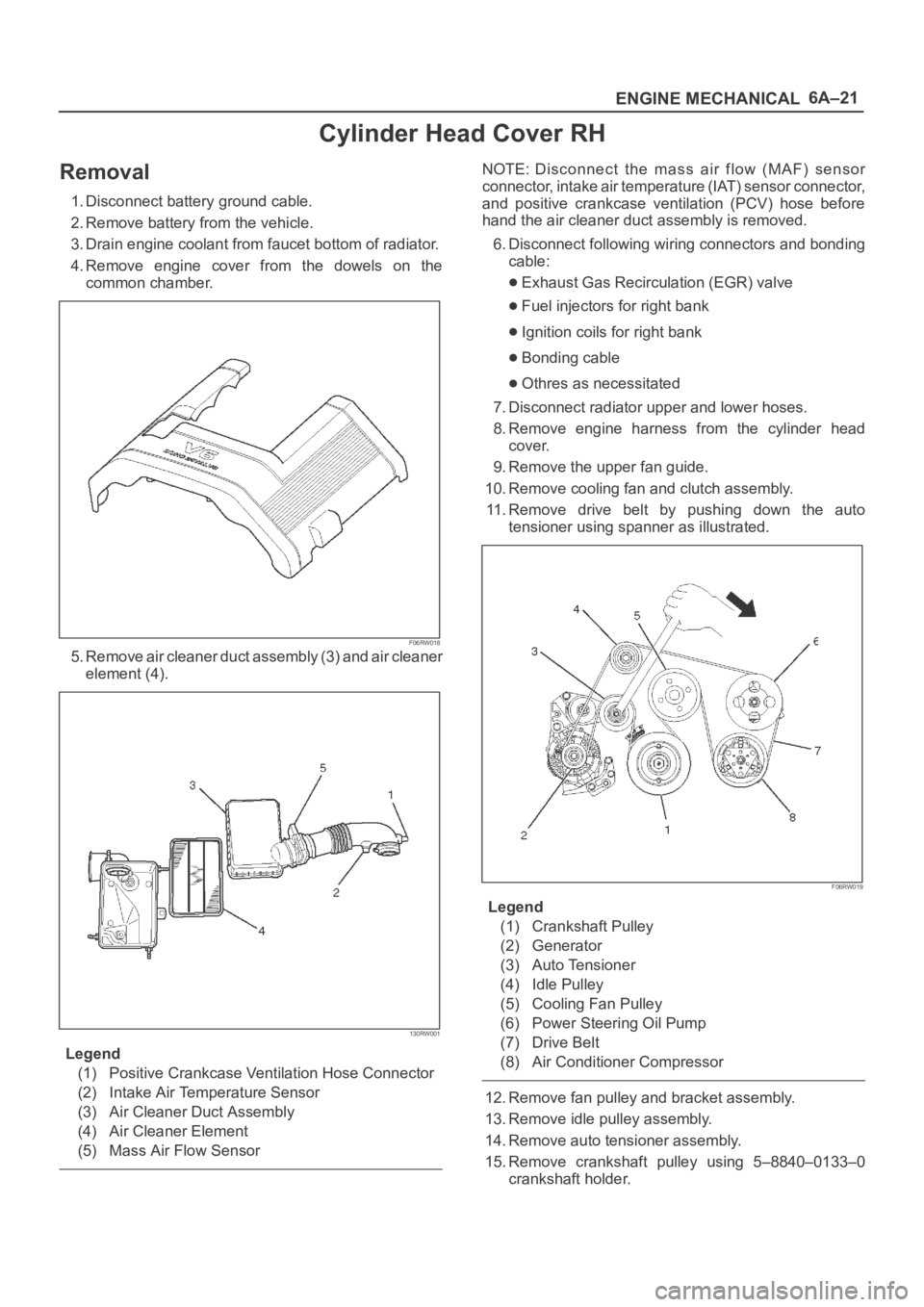
4. Remove engine cover from the dowels on the
common chamber.
F06RW018
5. Remove air cleaner duct assembly (3) and air cleaner
element (4).
130RW001
Legend
(1) Positive Crankcase Ventilation Hose Connector
(2) Intake Air Temperature Sensor
(3) Air Cleaner Duct Assembly
(4) Air Cleaner Element
(5) Mass Air Flow Sensor
NOTE: Disconnect the mass air flow (MAF) sensor
connector, intake air temperature (IAT) sensor connector,
and positive crankcase ventilation (PCV) hose before
hand the air cleaner duct assembly is removed.
6. Disconnect following wiring connectors and bonding
cable:
Exhaust Gas Recirculation (EGR) valve
Fuel injectors for right bank
Ignition coils for right bank
Bonding cable
Othres as necessitated
7. Disconnect radiator upper and lower hoses.
8. Remove engine harness from the cylinder head
cover.
9. Remove the upper fan guide.
10. Remove cooling fan and clutch assembly.
11. Remove drive belt by pushing down the auto
tensioner using spanner as illustrated.
F06RW019
Legend
(1) Crankshaft Pulley
(2) Generator
(3) Auto Tensioner
(4) Idle Pulley
(5) Cooling Fan Pulley
(6) Power Steering Oil Pump
(7) Drive Belt
(8) Air Conditioner Compressor
12. Remove fan pulley and bracket assembly.
13. Remove idle pulley assembly.
14. Remove auto tensioner assembly.
15. Remove crankshaft pulley using 5–8840–0133–0
crankshaft holder.
Page 4519 of 6000
6A–23
ENGINE MECHANICAL
6. Install idle pulley assembly and tighten the fixing bolt
to the specified torque.
Torque : 52 Nꞏm (5.3 Kgꞏm/38.4 lb ft)
7. Install fan pulley and bracket assembly and tighten
the fixing bolts and nut to the specified torque.
Torque : 22 Nꞏm (2.2 Kgꞏm/16.2 lb ft)
8. Install drive belt by pushing down the auto tensioner
using spanner as shown in the removal step of drive
belt.
9. Install cooling fan clutch assembly and tighten the
fixing bolts to the specified torque.
Torque : 10 Nꞏm (1.0 Kgꞏm/88.5 lb in)
10. Install upper fan guide and clip both side and tighten
the fixing bolts to the specified torque.
Torque : 4 Nꞏm (0.4 Kgꞏm/35.4 lb in)
11. Install engine harness and tighten the fixing bolts of
the retaining clip and brackets to the specified torque.
Torque : 4 Nꞏm (0.4 Kgꞏm/35.4 lb in)
12. Connect radiator upper and lower hoses and clip
them securely.
13. Connect wiring connectors and bonding cable of
those which were disconnected in the removal step.
14. Install air cleaner element and air cleaner duct
assembly, and the clip both end securely.
15. Connect MAF sensor connector, IAT sensor
connector and PCV hose.
16. Install engine cover mating with the dowels.