Page 12 of 6000
PAGE BACK PAGE NEXT
THIS MALUAL INCLUDES THE FOLLOWING SECTIONS:
SECTION No. CONTRNTS
8A LIGHTING SYSTEM
8B WIPER / WASHER SYSTEM
8C ENTERTAINMENT
8D WIRING SYSTEM
8E METER AND GAUGE
8F BODY STRUCTURE
8G SEATS
8H SECURITY AND LOCKS
8I SUN ROOF/CONVERTIBLE TOP
8J EXTERIOR / INTERIOR TRIM
HOME
8A
8B
8C
8D
8E
8F
8G
8H
8I
8J
Page 278 of 6000

COMPRESSOR SHAFT SEAL
Service Precaution
When replacing the shaft seal assembly, pressure relief
valve or control switches, it will be necessary to recover
the refrigerant. Other than clutch repair procedures, the
same holds true for any disassembly of the compressor.
A clean workbench covered with a sheet of clean
paper, and a place (clean trays, etc) for all parts being
removed and replaced is important, as is the use of
proper clean service tools.
CAUTION: Any attempt to use makeshift or
inadequate service tools or equipment may result
in damage and/or improper compressor operation.
All parts required for servicing the internal compressor
are protected by a preservative process and packaged
in a manner which will eliminate the necessity of
cleaning, washing or flushing of the parts. The parts
can be used in the internal assembly just as they are
removed from the service package. Seals and
protective packaging should be left intact until just
prior to installation.
If the compressor rear head, front head or cylinder and
shaft assembly is to be serviced or replaced, the oil in
the compressor must be drained, measured, recorded
and replaced.
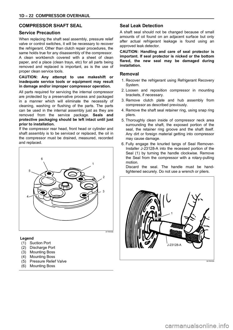
Legend
(1) Suction Port
(2) Discharge Port
(3) Mounting Boss
(4) Mounting Boss
(5) Pressure Relief Valve
(6) Mounting Boss
Seal Leak Detection
A shaft seal should not be changed because of small
amounts of oil found on an adjacent surface but only
after actual refrigerant leakage is found using an
approved leak detector.
CAUTION: Handling and care of seal protector is
important. If seal protector is nicked or the bottom
flared, the new seal may be damaged during
installation.
Removal
1. Recover the refrigerant using Refrigerant Recovery
System.
2. Loosen and reposition compressor in mounting
brackets, if necessary.
3. Remove clutch plate and hub assembly from
compressor as described previously.
4. Remove the shaft seal retainer ring, using snap ring
pliers.
5. Thoroughly clean inside of compressor neck area
surrounding the shaft, the exposed portion of the
seal, the retainer ring groove and the shaft itself.
Any dirt or foreign material getting into compressor
may cause damage.
6. Fully engage the knurled tangs of Seal Remover-
Installer J-23128-A into the recessed portion of the
Seal (1) by turning the handle clockwise. Remove
the Seal from the compressor with a rotary-pulling
motion.
Discard the seal. The handle must be hand-
tightened securely. Do not use a wrench or pliers.
1
2
3
456
871RW006
J-23128-A1
901RW008
Page 461 of 6000
DIFFERENTIAL (FRONT) 4A1–24
Thickness of thrust washers available:
1.00 mm, 1.05 mm, 1.10 mm (0.039 in, 0.041 in,
0.043 in)
425RS050
5. Install lock pin. After lock pin installation, stake the
cage to secure the lock pin.
425RS051
Legend
(1) Staked Portion
(2) Lock Pin
6. Clean the ring gear threaded holes to remove the
locking agent. When installing the ring gear, apply
LOCTITE 271 or equivalent to all the threaded area
and half of the unthreaded area of the bolt.7. Tighten the bolts in diagonal sequence as illustrated.
Torque: 108 Nꞏm (11kgꞏm/80 lb ft)
NOTE: Discard used bolts and install new ones.
415RS016
Page 491 of 6000
4A2A–24
DIFFERENTIAL (REAR 220mm)
Thickness of thrust washers available:
0.80 mm, 0.90 mm, 1.00 mm 1.10 mm, 1.20 mm,
1.30 mm (0.031 in, 0.035 in, 0.039 in,0.043 in,
0.047 in, 0.051 in)
425RS050
5. Install lock pin. After lock pin installation, stake the
cage to secure the lock pin.
425RS051
Legend
(1) Staked Portion
(2) Lock Pin
6. Clean the ring gear threaded holes to remove the
locking agent. When installing the ring gear, apply
LOCTITE 271 or equivalent to all the threaded area
and half of the unthreaded area of the bolt.7. Tighten the bolts in diagonal sequence as illustrated.
Torque: 108 Nꞏm (11.0kgꞏm/80 lb ft)
NOTE: Discard used bolts and install new ones.
415RW036
Page 525 of 6000
4A2B–22DIFFERENTIAL (REAR 244mm)
2. Install the pinion mate gear with thrust washer by
engaging it with the side gears while turning both
pinion mate gears simultaneously in the same
direction.
425RS048
3. Install differential shaft.
1 . B e s u r e t o i n s t a l l t h e d i f f e r e n t i a l s h a f t s o t h a t i t i s i n
alignment with the lock pin hole in the differential
cage.
425RS049
4. Install lock pin.
After lock pin installation, stake the case to secure the
lock pin.
5. Install ring gear.6. Tighten the bolts in diagonal sequence as illustrated.
Torque: 177Nꞏm (18.0kgꞏm/130 lb ft)
NOTE: Discard used bolts and install new ones.
425RW033
Page 573 of 6000

DRIVE LINE CONTROL SYSTEM (TOD) 4B2–2
General Description
C07RW014–1
TOD (Torque on Demand) system is traction state control
system to vehicle.
Transfer Position and Drive Mode
Three drive modes can be selected through operation of
4WD switch and transfer lever.
Transfer Position
TOD SWModeDrive mode
HIGHON (NORMAL)2HRear wheel drive
OFF (PUSHED)TODElectronically controlled torque split
four wheel drive
4LON/OFF4LLow-speed mechanical lock-up four
wheel drive
The electronic control unit (ECU) judges the signals from
the transfer lever and controls the transfer drive mode
and shift-on-the-fly system status.
TOD Control
The TOD position usually drives the rear wheels, and
transmits the torque to the front wheels with the help of
electronically controlled torque split mechanism
according to running conditions encountered. The driving
force is directly transmitted to the rear wheels. This force
is split by the transfer and delivered to the front wheels.
The magnitude of the torque transmitted to the front
wheels is controlled by changing the pressing force of the
electromagnetic multi plate disk clutch built in the transfer
unit. The pressing force of the clutch is controlled bychanging the voltage to the electromagnetic coil mounted
to the rear of the clutch. When the clutch is completely
disengaged, the rear wheels are driven. When the clutch
is completely engaged, a rigid four wheel drive mode is
obtained. The torque split status is controlled
continuously between the rear wheel and four wheel drive
modes. This system includes front and rear speed
sensors, and throttle position sensor that monitors the
engine output.
The control unit receives signals sent from these sensors
and changes the pressing force of the electromagnetic
multi plate disk clutch to determine the torque distribution
on the front and rear wheels. Therefore, when the slip of
the rear wheels is increased against the current torque
level in the normal rear wheel drive mode, the control unit
Page 578 of 6000
4B2–7 DRIVE LINE CONTROL SYSTEM (TOD)
Check Lamp
Inform the following items.
Bulb check
Fail (fail alarm)
Trouble code
Diesel/gasoline MAP
821RW078
TOD ECU
This control unit is mounted to the front right hand seat via
a special bracket.
F07RW029
Page 582 of 6000

4B2–11 DRIVE LINE CONTROL SYSTEM (TOD)
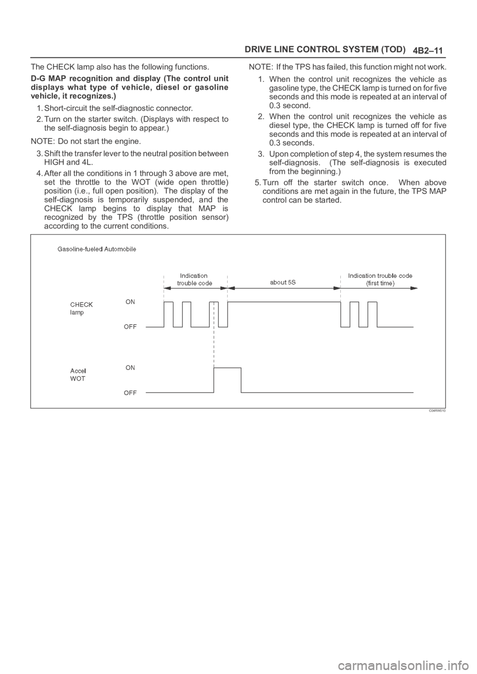
The CHECK lamp also has the following functions.
D-G MAP recognition and display (The control unit
displays what type of vehicle, diesel or gasoline
vehicle, it recognizes.)
1. Short-circuit the self-diagnostic connector.
2. Turn on the starter switch. (Displays with respect to
the self-diagnosis begin to appear.)
NOTE: Do not start the engine.
3. Shift the transfer lever to the neutral position between
HIGH and 4L.
4. After all the conditions in 1 through 3 above are met,
set the throttle to the WOT (wide open throttle)
position (i.e., full open position). The display of the
self-diagnosis is temporarily suspended, and the
CHECK lamp begins to display that MAP is
recognized by the TPS (throttle position sensor)
according to the current conditions.NOTE: If the TPS has failed, this function might not work.
1. When the control unit recognizes the vehicle as
gasoline type, the CHECK lamp is turned on for five
seconds and this mode is repeated at an interval of
0.3 second.
2. When the control unit recognizes the vehicle as
diesel type, the CHECK lamp is turned off for five
seconds and this mode is repeated at an interval of
0.3 seconds.
3. Upon completion of step 4, the system resumes the
self-diagnosis. (The self-diagnosis is executed
from the beginning.)
5. Turn off the starter switch once. When above
conditions are met again in the future, the TPS MAP
control can be started.
C04RW010