1998 OPEL FRONTERA key
[x] Cancel search: keyPage 4405 of 6000
5A–55 BRAKE CONTROL SYSTEM
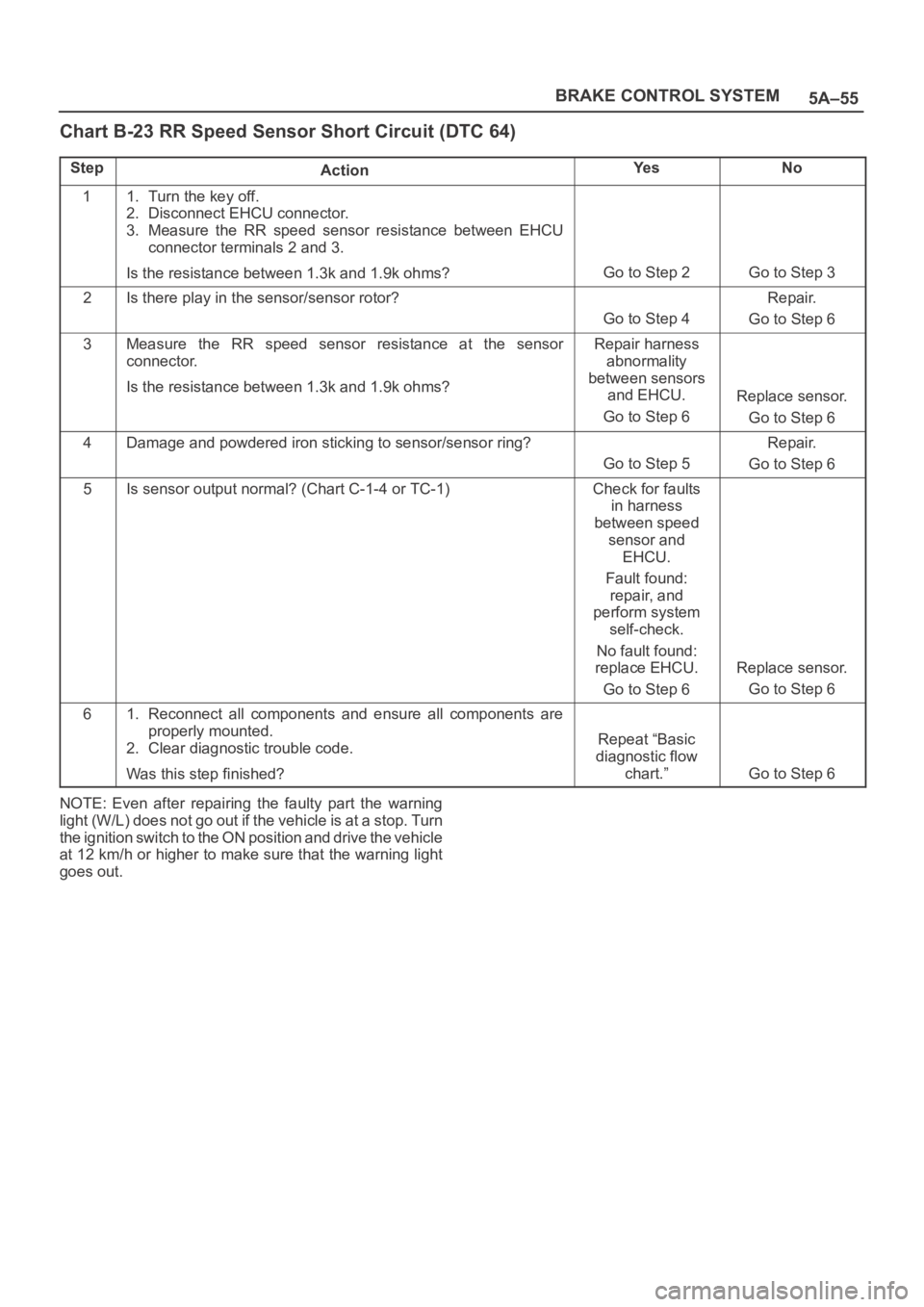
Chart B-23 RR Speed Sensor Short Circuit (DTC 64)
StepActionYe sNo
11. Turn the key off.
2. Disconnect EHCU connector.
3. Measure the RR speed sensor resistance between EHCU
connector terminals 2 and 3.
Is the resistance between 1.3k and 1.9k ohms?
Go to Step 2Go to Step 3
2Is there play in the sensor/sensor rotor?
Go to Step 4
Repair.
Go to Step 6
3Measure the RR speed sensor resistance at the sensor
connector.
Is the resistance between 1.3k and 1.9k ohms?Repair harness
abnormality
between sensors
and EHCU.
Go to Step 6
Replace sensor.
Go to Step 6
4Damage and powdered iron sticking to sensor/sensor ring?
Go to Step 5
Repair.
Go to Step 6
5Is sensor output normal? (Chart C-1-4 or TC-1)Check for faults
in harness
between speed
sensor and
EHCU.
Fault found:
repair, and
perform system
self-check.
No fault found:
replace EHCU.
Go to Step 6
Replace sensor.
Go to Step 6
61. Reconnect all components and ensure all components are
properly mounted.
2. Clear diagnostic trouble code.
Was this step finished?
Repeat “Basic
diagnostic flow
chart.”
Go to Step 6
NOTE: Even after repairing the faulty part the warning
light (W/L) does not go out if the vehicle is at a stop. Turn
the ignition switch to the ON position and drive the vehicle
at 12 km/h or higher to make sure that the warning light
goes out.
Page 4407 of 6000
5A–57 BRAKE CONTROL SYSTEM
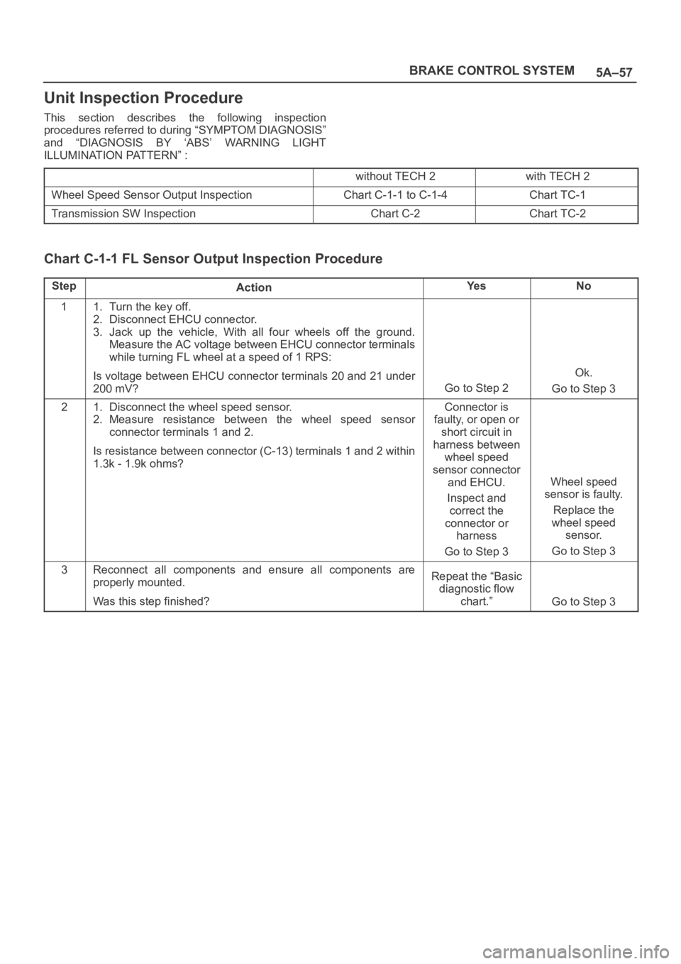
Unit Inspection Procedure
This section describes the following inspection
procedures referred to during “SYMPTOM DIAGNOSIS”
and “DIAGNOSIS BY ‘ABS’ WARNING LIGHT
ILLUMINATION PATTERN” :
without TECH 2with TECH 2
Wheel Speed Sensor Output InspectionChart C-1-1 to C-1-4Chart TC-1
Transmission SW InspectionChart C-2Chart TC-2
Chart C-1-1 FL Sensor Output Inspection Procedure
StepActionYe sNo
11. Turn the key off.
2. Disconnect EHCU connector.
3. Jack up the vehicle, With all four wheels off the ground.
Measure the AC voltage between EHCU connector terminals
while turning FL wheel at a speed of 1 RPS:
Is voltage between EHCU connector terminals 20 and 21 under
200 mV?
Go to Step 2
Ok.
Go to Step 3
21. Disconnect the wheel speed sensor.
2. Measure resistance between the wheel speed sensor
connector terminals 1 and 2.
Is resistance between connector (C-13) terminals 1 and 2 within
1.3k - 1.9k ohms?Connector is
faulty, or open or
short circuit in
harness between
wheel speed
sensor connector
and EHCU.
Inspect and
correct the
connector or
harness
Go to Step 3
Wheel speed
sensor is faulty.
Replace the
wheel speed
sensor.
Go to Step 3
3Reconnect all components and ensure all components are
properly mounted.
Was this step finished?Repeat the “Basic
diagnostic flow
chart.”
Go to Step 3
Page 4408 of 6000
5A–58
BRAKE CONTROL SYSTEM
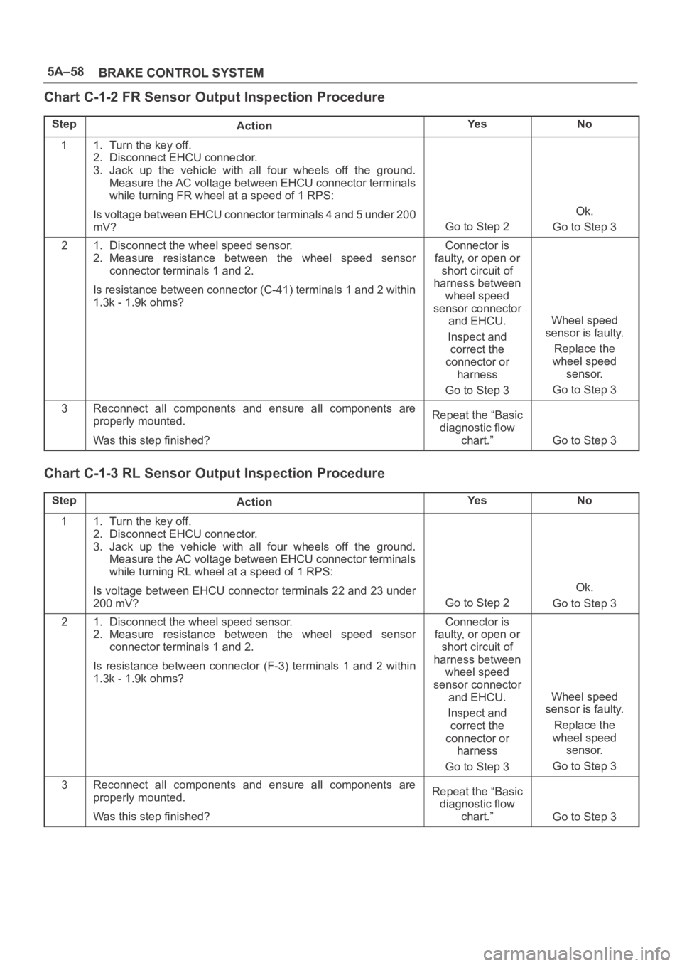
Chart C-1-2 FR Sensor Output Inspection Procedure
StepActionYe sNo
11. Turn the key off.
2. Disconnect EHCU connector.
3. Jack up the vehicle with all four wheels off the ground.
Measure the AC voltage between EHCU connector terminals
while turning FR wheel at a speed of 1 RPS:
Is voltage between EHCU connector terminals 4 and 5 under 200
mV?
Go to Step 2
Ok.
Go to Step 3
21. Disconnect the wheel speed sensor.
2. Measure resistance between the wheel speed sensor
connector terminals 1 and 2.
Is resistance between connector (C-41) terminals 1 and 2 within
1.3k - 1.9k ohms?Connector is
faulty, or open or
short circuit of
harness between
wheel speed
sensor connector
and EHCU.
Inspect and
correct the
connector or
harness
Go to Step 3
Wheel speed
sensor is faulty.
Replace the
wheel speed
sensor.
Go to Step 3
3Reconnect all components and ensure all components are
properly mounted.
Was this step finished?Repeat the “Basic
diagnostic flow
chart.”
Go to Step 3
Chart C-1-3 RL Sensor Output Inspection Procedure
StepActionYe sNo
11. Turn the key off.
2. Disconnect EHCU connector.
3. Jack up the vehicle with all four wheels off the ground.
Measure the AC voltage between EHCU connector terminals
while turning RL wheel at a speed of 1 RPS:
Is voltage between EHCU connector terminals 22 and 23 under
200 mV?
Go to Step 2
Ok.
Go to Step 3
21. Disconnect the wheel speed sensor.
2. Measure resistance between the wheel speed sensor
connector terminals 1 and 2.
Is resistance between connector (F-3) terminals 1 and 2 within
1.3k - 1.9k ohms?Connector is
faulty, or open or
short circuit of
harness between
wheel speed
sensor connector
and EHCU.
Inspect and
correct the
connector or
harness
Go to Step 3
Wheel speed
sensor is faulty.
Replace the
wheel speed
sensor.
Go to Step 3
3Reconnect all components and ensure all components are
properly mounted.
Was this step finished?Repeat the “Basic
diagnostic flow
chart.”
Go to Step 3
Page 4409 of 6000
5A–59 BRAKE CONTROL SYSTEM
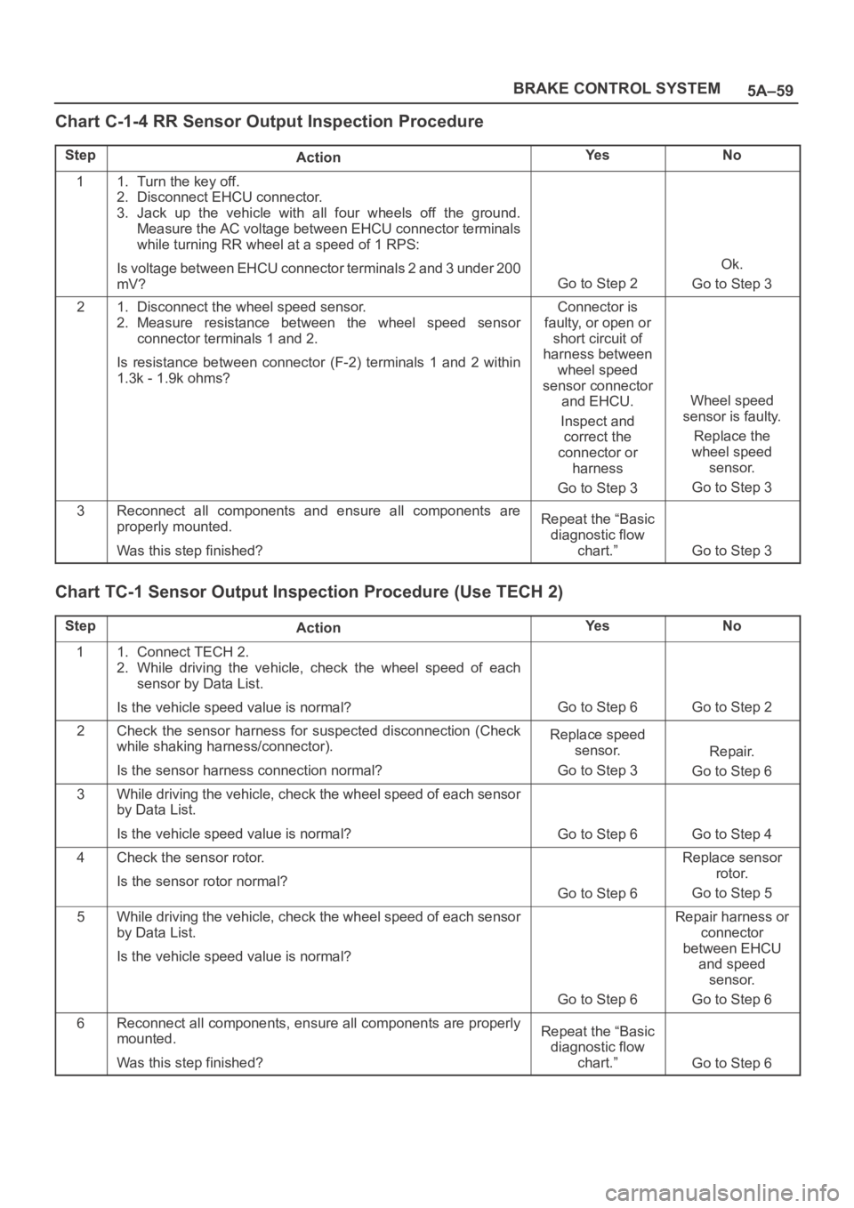
Chart C-1-4 RR Sensor Output Inspection Procedure
StepActionYe sNo
11. Turn the key off.
2. Disconnect EHCU connector.
3. Jack up the vehicle with all four wheels off the ground.
Measure the AC voltage between EHCU connector terminals
while turning RR wheel at a speed of 1 RPS:
Is voltage between EHCU connector terminals 2 and 3 under 200
mV?
Go to Step 2
Ok.
Go to Step 3
21. Disconnect the wheel speed sensor.
2. Measure resistance between the wheel speed sensor
connector terminals 1 and 2.
Is resistance between connector (F-2) terminals 1 and 2 within
1.3k - 1.9k ohms?Connector is
faulty, or open or
short circuit of
harness between
wheel speed
sensor connector
and EHCU.
Inspect and
correct the
connector or
harness
Go to Step 3
Wheel speed
sensor is faulty.
Replace the
wheel speed
sensor.
Go to Step 3
3Reconnect all components and ensure all components are
properly mounted.
Was this step finished?Repeat the “Basic
diagnostic flow
chart.”
Go to Step 3
Chart TC-1 Sensor Output Inspection Procedure (Use TECH 2)
StepActionYe sNo
11. Connect TECH 2.
2. While driving the vehicle, check the wheel speed of each
sensor by Data List.
Is the vehicle speed value is normal?
Go to Step 6Go to Step 2
2Check the sensor harness for suspected disconnection (Check
while shaking harness/connector).
Is the sensor harness connection normal?Replace speed
sensor.
Go to Step 3
Repair.
Go to Step 6
3While driving the vehicle, check the wheel speed of each sensor
by Data List.
Is the vehicle speed value is normal?
Go to Step 6Go to Step 4
4Check the sensor rotor.
Is the sensor rotor normal?
Go to Step 6
Replace sensor
rotor.
Go to Step 5
5While driving the vehicle, check the wheel speed of each sensor
by Data List.
Is the vehicle speed value is normal?
Go to Step 6
Repair harness or
connector
between EHCU
and speed
sensor.
Go to Step 6
6Reconnect all components, ensure all components are properly
mounted.
Was this step finished?Repeat the “Basic
diagnostic flow
chart.”
Go to Step 6
Page 4410 of 6000
5A–60
BRAKE CONTROL SYSTEM
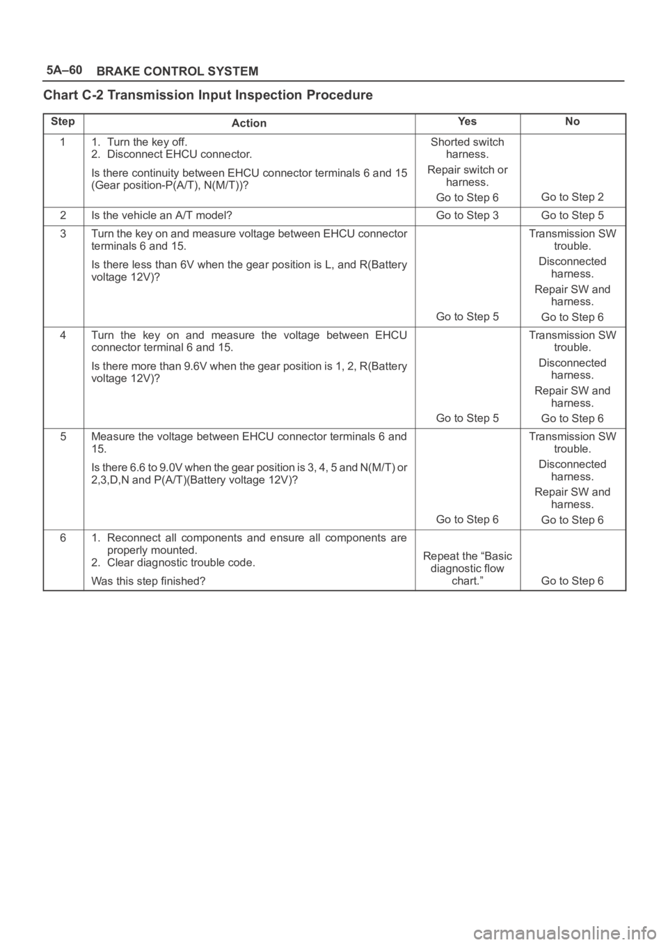
Chart C-2 Transmission Input Inspection Procedure
StepActionYe sNo
11. Turn the key off.
2. Disconnect EHCU connector.
Is there continuity between EHCU connector terminals 6 and 15
(Gear position-P(A/T), N(M/T))?Shorted switch
harness.
Repair switch or
harness.
Go to Step 6
Go to Step 2
2Is the vehicle an A/T model?Go to Step 3Go to Step 5
3Turn the key on and measure voltage between EHCU connector
terminals 6 and 15.
Is there less than 6V when the gear position is L, and R(Battery
voltage 12V)?
Go to Step 5
Transmission SW
trouble.
Disconnected
harness.
Repair SW and
harness.
Go to Step 6
4Turn the key on and measure the voltage between EHCU
connector terminal 6 and 15.
Is there more than 9.6V when the gear position is 1, 2, R(Battery
voltage 12V)?
Go to Step 5
Transmission SW
trouble.
Disconnected
harness.
Repair SW and
harness.
Go to Step 6
5Measure the voltage between EHCU connector terminals 6 and
15.
Is there 6.6 to 9.0V when the gear position is 3, 4, 5 and N(M/T) or
2,3,D,N and P(A/T)(Battery voltage 12V)?
Go to Step 6
Transmission SW
trouble.
Disconnected
harness.
Repair SW and
harness.
Go to Step 6
61. Reconnect all components and ensure all components are
properly mounted.
2. Clear diagnostic trouble code.
Was this step finished?
Repeat the “Basic
diagnostic flow
chart.”
Go to Step 6
Page 4617 of 6000
6C–10
ENGINE FUEL
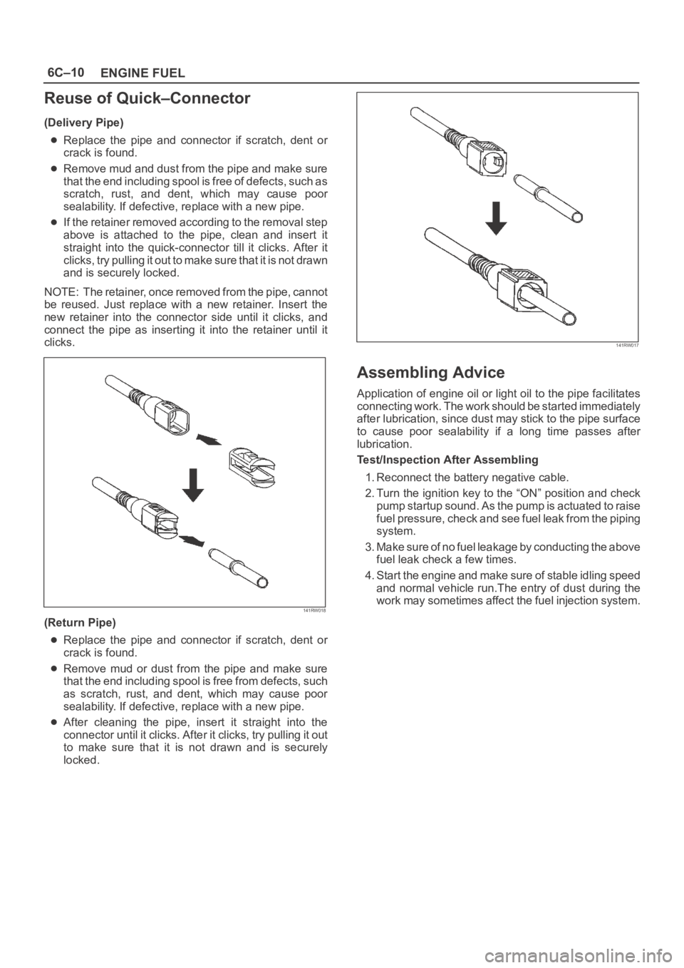
Reuse of Quick–Connector
(Delivery Pipe)
Replace the pipe and connector if scratch, dent or
crack is found.
Remove mud and dust from the pipe and make sure
that the end including spool is free of defects, such as
scratch, rust, and dent, which may cause poor
sealability. If defective, replace with a new pipe.
If the retainer removed according to the removal step
above is attached to the pipe, clean and insert it
straight into the quick-connector till it clicks. After it
clicks, try pulling it out to make sure that it is not drawn
and is securely locked.
NOTE: The retainer, once removed from the pipe, cannot
be reused. Just replace with a new retainer. Insert the
new retainer into the connector side until it clicks, and
connect the pipe as inserting it into the retainer until it
clicks.
141RW018
(Return Pipe)
Replace the pipe and connector if scratch, dent or
crack is found.
Remove mud or dust from the pipe and make sure
that the end including spool is free from defects, such
as scratch, rust, and dent, which may cause poor
sealability. If defective, replace with a new pipe.
After cleaning the pipe, insert it straight into the
connector until it clicks. After it clicks, try pulling it out
to make sure that it is not drawn and is securely
locked.
141RW017
Assembling Advice
Application of engine oil or light oil to the pipe facilitates
connecting work. The work should be started immediately
after lubrication, since dust may stick to the pipe surface
to cause poor sealability if a long time passes after
lubrication.
Test/Inspection After Assembling
1. Reconnect the battery negative cable.
2. Turn the ignition key to the “ON” position and check
pump startup sound. As the pump is actuated to raise
fuel pressure, check and see fuel leak from the piping
system.
3. Make sure of no fuel leakage by conducting the above
fuel leak check a few times.
4. Start the engine and make sure of stable idling speed
and normal vehicle run.The entry of dust during the
work may sometimes affect the fuel injection system.
Page 4697 of 6000
6E–40
ENGINE DRIVEABILITY AND EMISSIONS
Common OBD Terms
Diagnostic
When used as a noun, the word diagnostic refers to any
on-board test run by the vehicle’s Diagnostic
Management System. A diagnostic is simply a test run on
a system or component to determine if the system or
component is operating according to specification. There
are many diagnostics, shown in the following list:
Oxygen sensors
Oxygen sensor heaters
EGR
Catalyst monitoring
Enable Criteria
The term “enable criteria” is engineering language for the
conditions necessary for a given diagnostic test to run.
Each diagnostic has a specific list of conditions which
must be met before the diagnostic will run. “Enable
criteria” is another way of saying “conditions required”.
The enable criteria for each diagnostic is listed on the first
page of the DTC description under the heading
“Conditions for Setting the DTC”. Enable criteria varies
with each diagnostic, and typically includes, but is not
limited to the following items:
engine speed
vehicle speed
ECT
MAF/MAP
barometric pressure
IAT
TP
fuel trim
TCC enabled
A/C on
Tr i p
Technically, a trip is a key on-run-key off cycle in which all
the enable criteria for a given diagnostic are met, allowing
the diagnostic to run. Unfortunately, this concept is not
quite that simple. A trip is official when all the enable
criteria for a given diagnostic are met. But because the
enable criteria vary from one diagnostic to another, the
definition of trip varies as well. Some diagnostic are run
when the vehicle is at operating temperature, some when
the vehicle first start up; some require that the vehicle be
cruising at a steady highway speed, some run only when
the vehicle is idle; some diagnostics function with the
TCC disables. Some run only immediately following a
cold engine start-up.
A trip then, is defined as a key on-run-key off cycle in
which the vehicle was operated in such a way as to satisfy
the enables criteria for a given diagnostic, and this
diagnostic will consider this cycle to be one trip. However,
another diagnostic with a different set of enable criteria
(which were not met) during this driving event, would not
consider it a trip. No trip will occur for that particular
diagnostic until the vehicle is driven in such a way as to
meet all the enable criteria.
The Diagnostic Executive
The Diagnostic Executive is a unique segment of
software which is designed to coordinate and prioritize
the diagnostic procedures as well as define the protocol
for recording and displaying their results. The main
responsibilities of the Diagnostic Executive are listed as
following:
Commanding the MIL (“Check Engine” lamp) on and
off
DTC logging and clearing
Freeze Frame data for the first emission related DTC
recorded
Non-emission related Service Lamp (future)
Operating conditions Failure Records buffer, (the
number of records will vary)
Current status information on each diagnostic
The Diagnostic Executive records DTCs and turns on the
MIL when emission-related faults occur. It can also turn
off the MIL if the conditions cease which caused the DTC
to set.
Diagnostic Information
The diagnostic charts and functional checks are designed
to locate a faulty circuit or component through a process
of logical decisions. The charts are prepared with the
requirement that the vehicle functioned correctly at the
time of assembly and that there are not multiple faults
present.
There is a continuous self-diagnosis on certain control
functions. This diagnostic capability is complemented by
the diagnostic procedures contained in this manual. The
language of communicating the source of the malfunction
is a system of diagnostic trouble codes. When a
malfunction is detected by the control module, a
diagnostic trouble code is set and the Malfunction
Indicator Lamp (MIL) (“Check Engine” lamp) is
illuminated.
Malfunction Indicator Lamp (MIL)
The Malfunction Indicator Lamp (MIL) looks the same as
the MIL you are already familiar with (“Check Engine”
lamp). However, OBD requires that the it illuminate under
a strict set of guide lines.
Basically, the MIL is turned on when the PCM detects a
DTC that will impact the vehicle emissions.
The MIL is under the control of the Diagnostic Executive.
The MIL will be turned on if an emissions-related
diagnostic test indicates a malfunction has occurred. It
will stay on until the system or component passes the
same test, for three consecutive trips, with no
emissionsrelated faults.
Extinguishing the MIL
When the MIL is on, the Diagnostic Executive will turn off
the MIL after
three consecutive trips that a “test passed”
has been reported for the diagnostic test that originally
caused the MIL to illuminate.
Although the MIL has been turned off, the DTC will remain
in the PCM memory (both Freeze Frame and Failure
Records) until
forty(40) warm-up cycles after no faults
have been completed.
Page 4698 of 6000
6E–41 ENGINE DRIVEABILITY AND EMISSIONS
If the MIL was set by either a fuel trim or misfire-related
DTC, additional requirements must be met. In addition to
the requirements stated in the previous paragraph, these
requirements are as follows:
The diagnostic tests that are passed must occur with
375 RPM of the RPM data stored at the time the last
test failed.
Plus or minus ten (10) percent of the engine load that
was stored at the time the last failed.
Similar engine temperature conditions (warmed up or
warming up ) as those stored at the time the last test
failed.
Meeting these requirements ensures that the fault which
turned on the MIL has been corrected.
The MIL (“Check Engine” lamp) is on the instrument
panel and has the following function:
It informs the driver that a fault affects vehicle emission
levels has occurred and that the vehicle should be
taken for service as soon as possible.
As a bulb and system check, the MIL will come “ON”
with the key “ON” and the engine not running. When
the engine is started, the MIL will turn “OFF.”
When the MIL remains “ON” while the engine is
running, or when a malfunction is suspected due to a
driveability or emissions problem, a Powertrain
On-Board Diagnostic (OBD ll) System Check must be
performed. The procedures for these checks are given
in On-Board Diagnostic (OBD) System Check. These
checks will expose faults which may not be detected if
other diagnostics are performed first.
DTC Types
Each DTC is directly related to a diagnostic test. The
Diagnostic Management System sets DTC based on the
failure of the tests during a trip or trips. Certain tests must
fail two (2) consecutive trips before the DTC is set. The
following are the four (4) types of DTCs and the
characteristics of those codes:
Ty p e A
Emissions related
Requests illumination of the MIL of the first trip with a
fail
Stores a History DTC on the first trip with a fail
Stores a Freeze Frame (if empty)
Stores a Fail Record
Updates the Fail Record each time the diagnostic
test fails
Ty p e B
Emissions related
“Armed” after one (1) trip with a fail
“Disarmed” after one (1) trip with a pass
Requests illumination of the MIL on the second
consecutive trip
with a fail
Stores a History DTC on the second consecutive trip
with a fail (The DTC will be armed after the first fail)
Stores a Freeze Frame on the second consecutive
trip with a fail (if empty)
Stores a Fail Record when the first test fails (not
dependent on
consecutive trip fails)
Updates the Fail Record each time the diagnostic
test fails
Type C (if the vehicle is so equipped)
Non-Emissions related
Requests illumination of the Service Lamp or the
service message on the Drive Information Center
(DIC) on the
first trip with a fail
Stores a History DTC on the first trip with a fail
Does not store a Freeze Frame
Stores Fail Record when test fails
Updates the Fail Record each time the diagnostic
test fails
Type D (Ty p e D non-emissions related are not utilized
on certain vehicle applications).
Non-Emissions related
Dose not request illumination of any lamp
Stores a History DTC on the first trip with a fail
Does not store a Freeze Frame
Stores Fail Record when test fails
Updates the Fail Record each time the diagnostic
test fails
IMPORTANT:Only four Fail Records can be stored.
Each Fail Record is for a different DTC. It is possible that
there will not be Fail Records for every DTC if multiple
DTCs are set.
Storing and Erasing Freeze Frame Data and Failure
Records
The data captured is called Freeze Frame data. The
Freeze Frame data is very similar to a single record of
operating conditions. Whenever the MIL is illuminated,
the corresponding record of operating conditions is
recorded to the Freeze Frame buffer.
Data from these faults take precedence over data
associated with any other fault. The Freeze Frame data
will not be erased unless the associated history DTC is
cleared.
Each time a diagnostic test reports a failure, the current
engine operating conditions are recorded in the
Failure
Records
buffer. A subsequent failure will update the
recorded operating conditions. The following operating
conditions for the diagnostic test which failed
typically
include the following parameters:
Air Fuel Ratio
Air Flow Rate
Fuel Trim
Engine Speed
Engine Load
Engine Coolant Temperature
Vehicle Speed
TP Angle
MAP/BARO
Injector Base Pulse Width
Loop Status