1998 OPEL FRONTERA key
[x] Cancel search: keyPage 5708 of 6000
7A–19 AUTOMATIC TRANSMISSION (4L30–E)
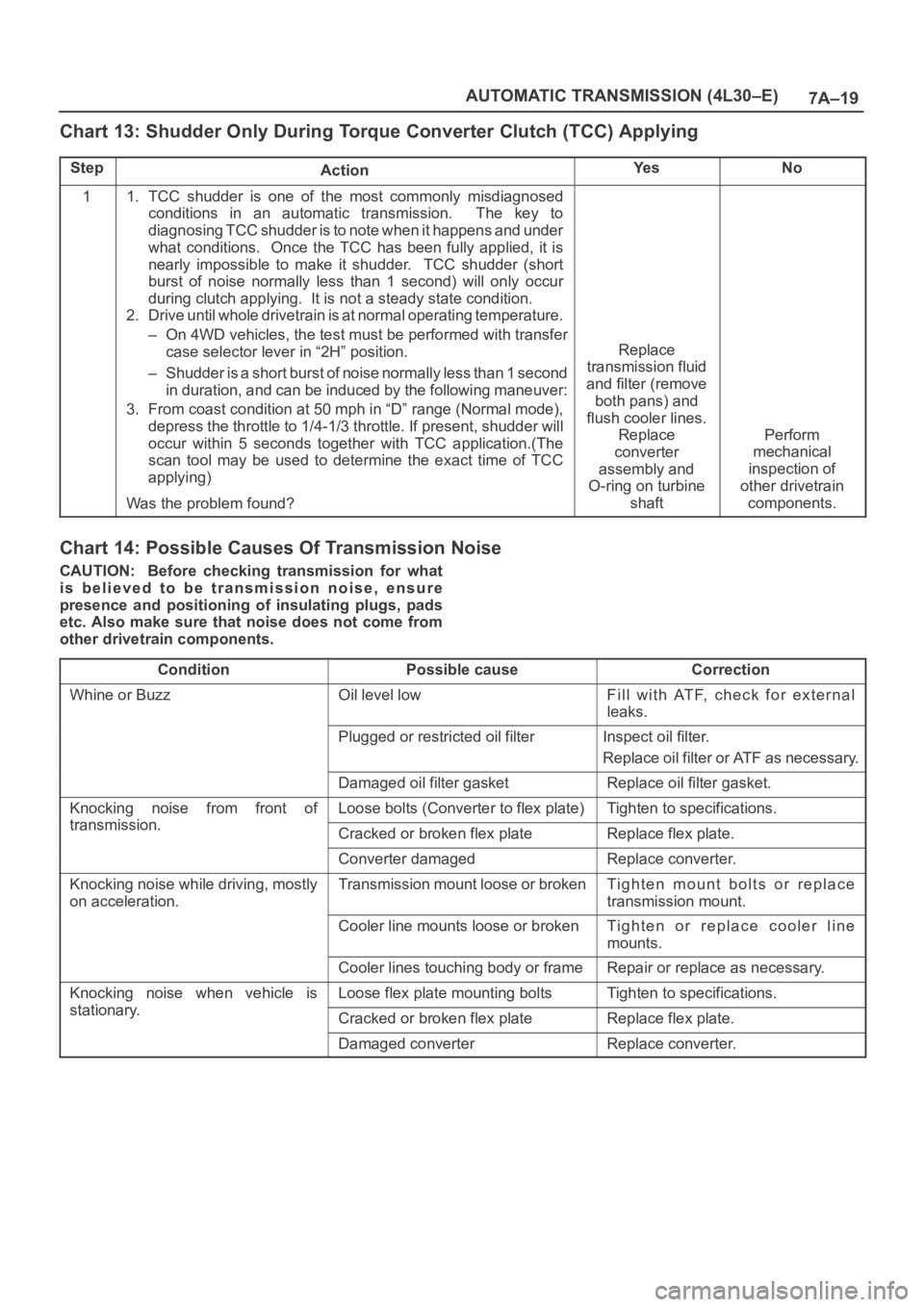
Chart 13: Shudder Only During Torque Converter Clutch (TCC) Applying
StepActionYe sNo
11. TCC shudder is one of the most commonly misdiagnosed
conditions in an automatic transmission. The key to
diagnosing TCC shudder is to note when it happens and under
what conditions. Once the TCC has been fully applied, it is
nearly impossible to make it shudder. TCC shudder (short
burst of noise normally less than 1 second) will only occur
during clutch applying. It is not a steady state condition.
2. Drive until whole drivetrain is at normal operating temperature.
– On 4WD vehicles, the test must be performed with transfer
case selector lever in “2H” position.
– Shudder is a short burst of noise normally less than 1 second
in duration, and can be induced by the following maneuver:
3. From coast condition at 50 mph in “D” range (Normal mode),
depress the throttle to 1/4-1/3 throttle. If present, shudder will
occur within 5 seconds together with TCC application.(The
scan tool may be used to determine the exact time of TCC
applying)
Was the problem found?
Replace
transmission fluid
and filter (remove
both pans) and
flush cooler lines.
Replace
converter
assembly and
O-ring on turbine
shaft
Perform
mechanical
inspection of
other drivetrain
components.
Chart 14: Possible Causes Of Transmission Noise
CAUTION: Before checking transmission for what
is believed to be transmission noise, ensure
presence and positioning of insulating plugs, pads
etc. Also make sure that noise does not come from
other drivetrain components.
Condition
Possible causeCorrection
Whine or BuzzOil level lowFill with ATF, check for external
leaks.
Plugged or restricted oil filterInspect oil filter.
Replace oil filter or ATF as necessary.
Damaged oil filter gasketReplace oil filter gasket.
Knocking noise from front of
transmission
Loose bolts (Converter to flex plate)Tighten to specifications.
transmission.Cracked or broken flex plateReplace flex plate.
Converter damagedReplace converter.
Knocking noise while driving, mostly
on acceleration.Transmission mount loose or brokenTighten mount bolts or replace
transmission mount.
Cooler line mounts loose or brokenTighten or replace cooler line
mounts.
Cooler lines touching body or frameRepair or replace as necessary.
Knocking noise when vehicle is
stationary
Loose flex plate mounting boltsTighten to specifications.
stationary.Cracked or broken flex plateReplace flex plate.
Damaged converterReplace converter.
Page 5719 of 6000
7A–30
AUTOMATIC TRANSMISSION (4L30–E)
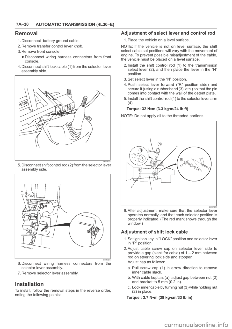
Removal
1. Disconnect battery ground cable.
2. Remove transfer control lever knob.
3. Remove front console.
Disconnect wiring harness connectors from front
console.
4. Disconnect shift lock cable (1) from the selector lever
assembly side.
256RW012
5. Disconnect shift control rod (2) from the selector lever
assembly side.
256RW013
6. Disconnect wiring harness connectors from the
selector lever assembly.
7. Remove selector lever assembly.
Installation
To install, follow the removal steps in the reverse order,
noting the following points:
Adjustment of select lever and control rod
1. Place the vehicle on a level surface.
NOTE: If the vehicle is not on level surface, the shift
select cable set positions will vary with the movement of
engine. To prevent possible misadjustment of the cable,
the vehicle must be placed on a level surface.
2. Install the shift control rod (1) to the transmission
select lever (2), and then place the lever in the “N”
position.
3. Set select lever in the “N” position.
4. Push select lever forward (“R” position side) and
s e c u r e i t ( u s i n g a r u b b e r b a n d ( 3 ) , e t c . ) s o t h a t t h e p i n
comes into contact with the wall of the detent plate.
5. Install the shift control rod (1) to the selector lever arm
(4).
To r q u e : 3 2 N
m (3.3 kgꞏm/24 lb ft)
NOTE: Do not apply oil to the threaded portions.
256RW014
6. After adjustment, make sure that the selector lever
operates normally, and that each selector position is
properly indicated. (The red mark shows through the
window.)
Adjustment of shift lock cable
1. Set ignition key in “LOCK” position and selector lever
in “P” position.
2. Adjust cable screw cap on selector lever side to
provide a gap (slack for cable) of 1 – 2 mm between
rod on steering lock side and stopper.
Adjust cap as follows:
a. Pull screw cap (1) in arrow direction to remove
inner cable slack.
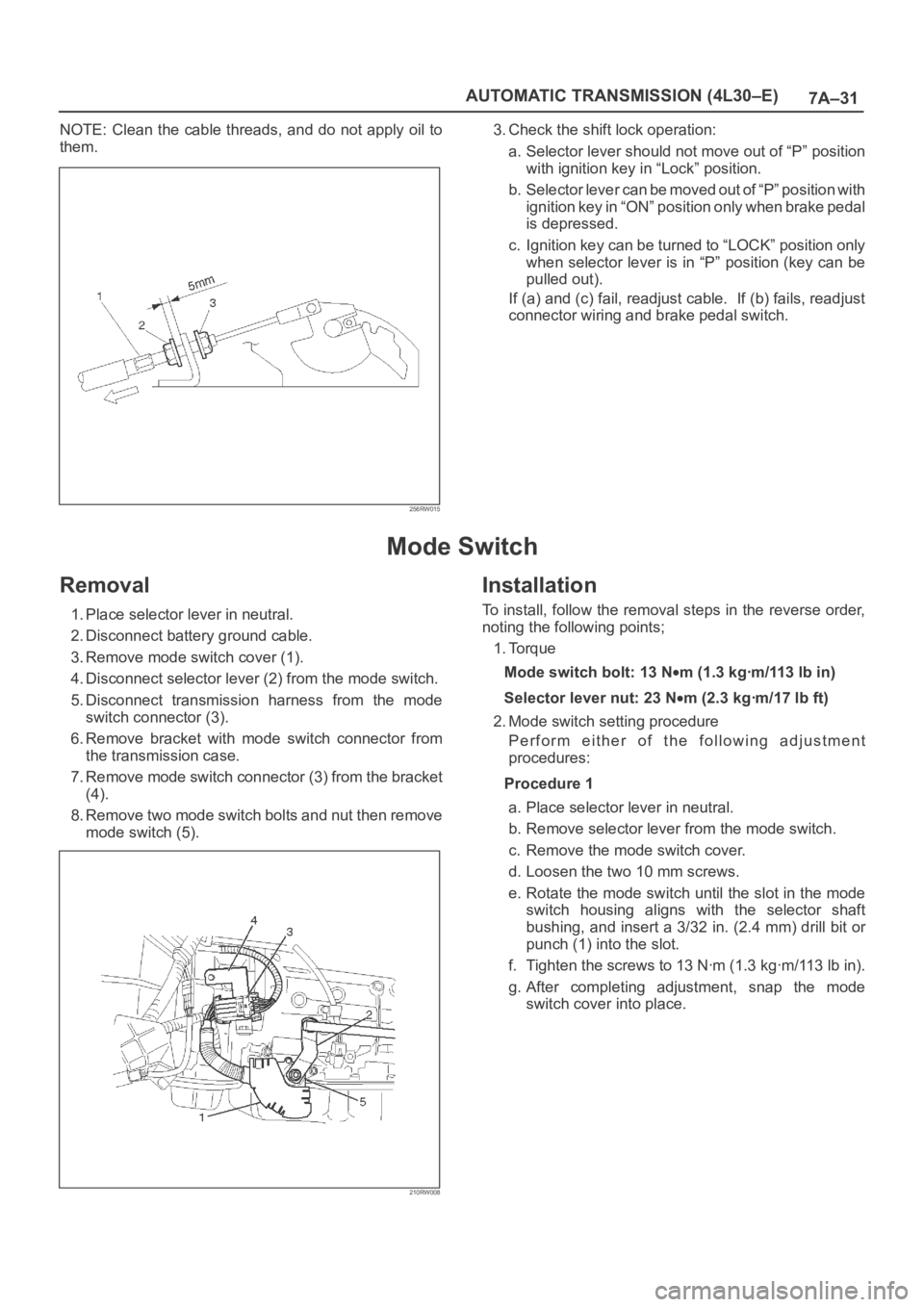
b. With cable kept as (a), adjust gap between nut (2)
and bracket to 5 mm (0.2 in).
c. Lock inner cable by turning nut (3) while holding nut
(2) in place.
Torque : 3.7 N
m (38 kgꞏcm/33 lb in)
Page 5720 of 6000
7A–31 AUTOMATIC TRANSMISSION (4L30–E)
NOTE: Clean the cable threads, and do not apply oil to
them.
256RW015
3. Check the shift lock operation:
a. Selector lever should not move out of “P” position
with ignition key in “Lock” position.
b. Selector lever can be moved out of “P” position with
ignition key in “ON” position only when brake pedal
is depressed.
c. Ignition key can be turned to “LOCK” position only
when selector lever is in “P” position (key can be
pulled out).
If (a) and (c) fail, readjust cable. If (b) fails, readjust
connector wiring and brake pedal switch.
Mode Switch
Removal
1. Place selector lever in neutral.
2. Disconnect battery ground cable.
3. Remove mode switch cover (1).
4. Disconnect selector lever (2) from the mode switch.
5. Disconnect transmission harness from the mode
switch connector (3).
6. Remove bracket with mode switch connector from
the transmission case.
7. Remove mode switch connector (3) from the bracket
(4).
8. Remove two mode switch bolts and nut then remove
mode switch (5).
210RW008
Installation
To install, follow the removal steps in the reverse order,
noting the following points;
1. Torque
Mode switch bolt: 13 N
m(1.3kgꞏm/113lbin)
Selector lever nut: 23 N
m (2.3 kgꞏm/17 lb ft)
2. Mode switch setting procedure
Perform either of the following adjustment
procedures:
Procedure 1
a. Place selector lever in neutral.
b. Remove selector lever from the mode switch.
c. Remove the mode switch cover.
d. Loosen the two 10 mm screws.
e. Rotate the mode switch until the slot in the mode
switch housing aligns with the selector shaft
bushing, and insert a 3/32 in. (2.4 mm) drill bit or
punch (1) into the slot.
f. Tighten the screws to 13 Nꞏm (1.3 kgꞏm/113 lb in).
g. After completing adjustment, snap the mode
switch cover into place.
Page 5795 of 6000
7A–14 AUTOMATIC TRANSMISSION (AW30-40LE)
821RY00012
F07LV002
740RY00013
740RY00014
SELF-DIAGNOSIS
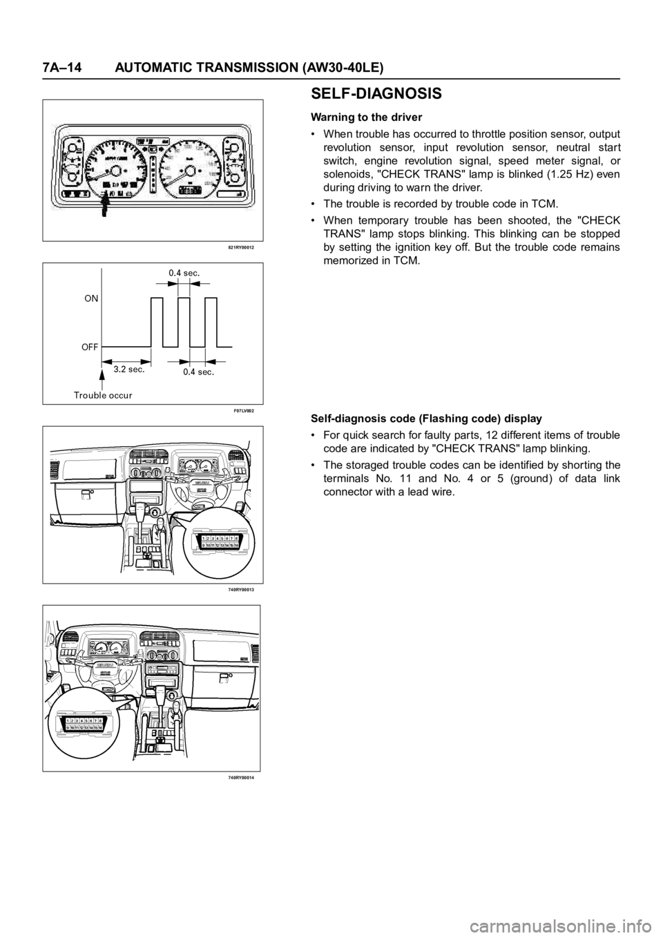
Warning to the driver
• When trouble has occurred to throttle position sensor, output
revolution sensor, input revolution sensor, neutral star t
switch, engine revolution signal, speed meter signal, or
solenoids, "CHECK TRANS" lamp is blinked (1.25 Hz) even
during driving to warn the driver.
• The trouble is recorded by trouble code in TCM.
• When temporary trouble has been shooted, the "CHECK
TRANS" lamp stops blinking. This blinking can be stopped
by setting the ignition key off. But the trouble code remains
memorized in TCM.
Self-diagnosis code (Flashing code) display
• For quick search for faulty parts, 12 different items of trouble
code are indicated by "CHECK TRANS" lamp blinking.
• The storaged trouble codes can be identified by shor ting the
terminals No. 11 and No. 4 or 5 (ground) of data link
connector with a lead wire.
Page 5796 of 6000
AUTOMATIC TRANSMISSION (AW30-40LE) 7A–15
F07LV001
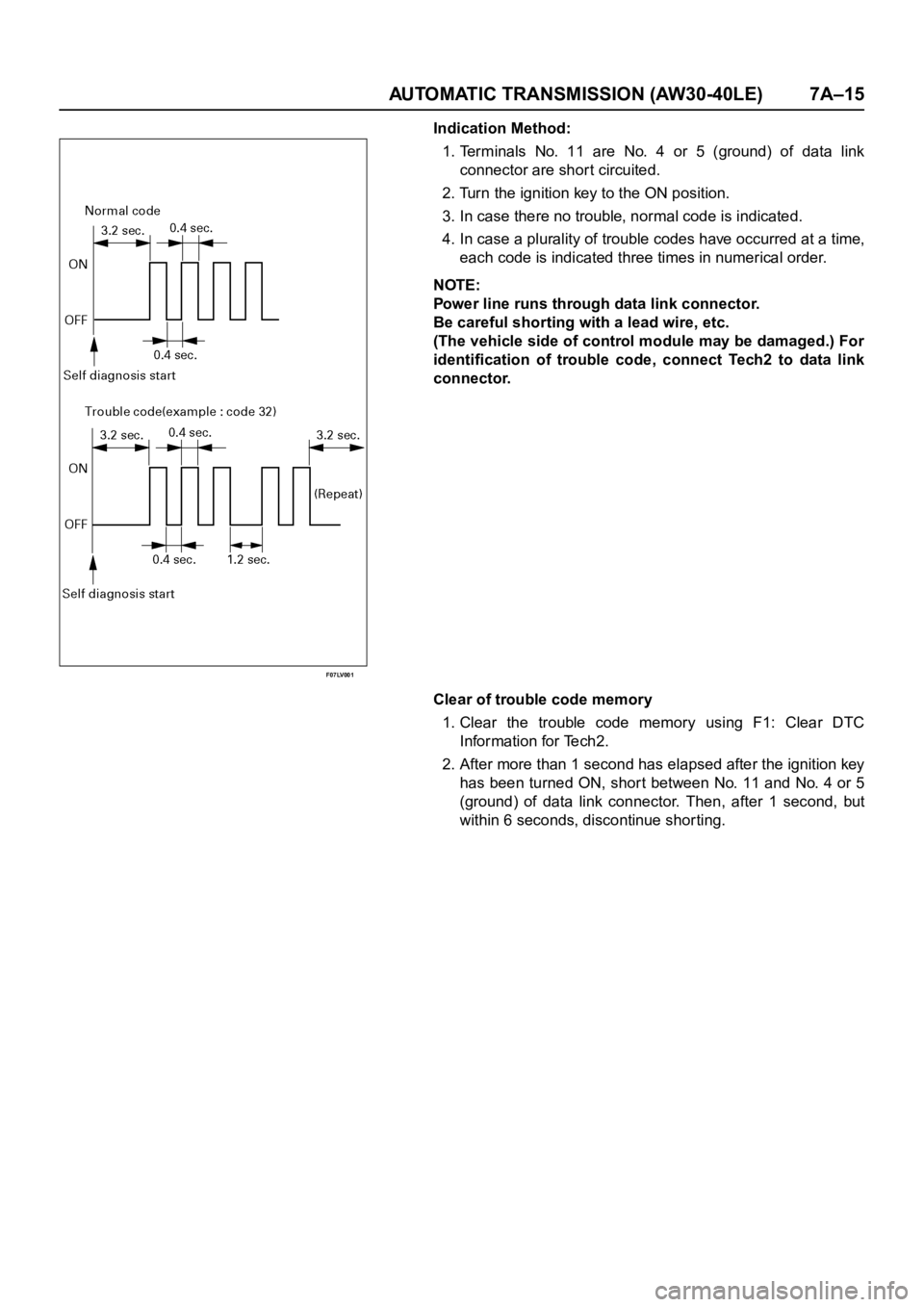
Indication Method:
1.Terminals No. 11 are No. 4 or 5 (ground) of data link
connector are short circuited.
2. Turn the ignition key to the ON position.
3. In case there no trouble, normal code is indicated.
4. In case a plurality of trouble codes have occurred at a time,
each code is indicated three times in numerical order.
NOTE:
Power line runs through data link connector.
Be careful shorting with a lead wire, etc.
(The vehicle side of control module may be damaged.) For
identification of trouble code, connect Tech2 to data link
connector.
Clear of trouble code memory
1. Clear the trouble code memory using F1: Clear DTC
Information for Tech2.
2. After more than 1 second has elapsed after the ignition key
has been turned ON, short between No. 11 and No. 4 or 5
(ground) of data link connector. Then, after 1 second, but
within 6 seconds, discontinue shorting.
Page 5799 of 6000
7A–18 AUTOMATIC TRANSMISSION (AW30-40LE)
901RW176
F07RW033
740RY00013
740RY00014
901RY00014
TECH2 CONNECTION
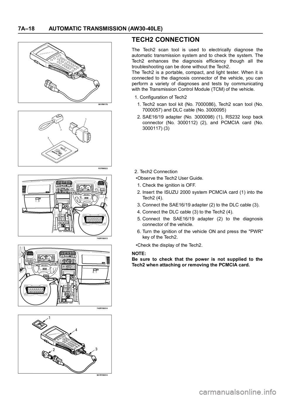
The Tech2 scan tool is used to electrically diagnose the
automatic transmission system and to check the system. The
Tech2 enhances the diagnosis efficiency though all the
troubleshooting can be done without the Tech2.
The Tech2 is a portable, compact, and light tester. When it is
connected to the diagnosis connector of the vehicle, you can
perform a variety of diagnoses and tests by communicating
with the Transmission Control Module (TCM) of the vehicle.
1. Configuration of Tech2
1. Tech2 scan tool kit (No. 7000086), Tech2 scan tool (No.
7000057) and DLC cable (No. 3000095)
2. SAE16/19 adapter (No. 3000098) (1), RS232 loop back
connector (No. 3000112) (2), and PCMCIA card (No.
3000117) (3)
2. Tech2 Connection
•Observe the Tech2 User Guide.
1. Check the ignition is OFF.
2. Inser t the ISUZU 2000 system PCMCIA card (1) into the
Te c h 2 ( 4 ) .
3. Connect the SAE16/19 adapter (2) to the DLC cable (3).
4. Connect the DLC cable (3) to the Tech2 (4).
5. Connect the SAE16/19 adapter (2) to the diagnosis
connector of the vehicle.
6. Turn the ignition of the vehicle ON and press the "PWR"
key of the Tech2.
•Check the display of the Tech2.
NOTE:
Be sure to check that the power is not supplied to the
Tech2 when attaching or removing the PCMCIA card.
Page 5801 of 6000

7A–20 AUTOMATIC TRANSMISSION (AW30-40LE)
Once the test vehicle has been identified an “Application
(Power train) Menu" screen appears. Please select the
appropriate application.
The following table shows, which functions are used for
the available equipment versions.
Diagnostic Trouble Codes
The purpose of the “Diagnostic Trouble Codes" mode is
to display stored TCM trouble codes.
When “Diagnostic Trouble Codes" is selected an
“Application Menu" screen appears.
Clear DTC Information
The purpose of the “Clear DTC Information" mode is to
command the clearing of stored TCM trouble codes.
When “Clear DTC Information" is selected, a “Clear
DTC Information", warning screen appears. This screen
informs you that by cleaning DTC's, “all stored DTC
information in controller will be erased".
Do you want to clear DTC's (Yes/No).
Press either the Yes or No key when answering.
After clearing codes, confirm system operation by test
driving the vehicle.
Allow the vehicle to shift through all four forward gears in
a manner which attempts to repeat the failure condition.
NOTE: When the trouble has not been repaired and thetrouble code cannot be erased, check the vehicle again.
DTC Information
When “DTC Information" is selected, an “Application
Menu" appears with a list of DTC information function
keys addressing DTC specifics and their origins.
Function key selections may vary for particular vehicle
and/or system.
Data Display
The purpose of the “Data Display" mode is to
continuously monitor data parameters.
The current actual values of all impor tant sensors and
signals in the system are display through F1 mode.
When “Data Display" is selected an “Application Menu"
appears.
See “TRANSMISSION DATA" and “TCC DATA” on next
page.
Snapshot
When “Snapshot" is selected an “Application Menu"
appears.
When “Transmission Snapshot" application is selected
from the “Application Menu", a “Snapshot Menu"
appears, displaying several options. “Snapshot" options
may vary from one system to another.
“Snapshot" allows a recording of all vehicle parameters.
There parameters may then be replayed at a future
point in time.
This action allows you to focus on making the condition
occur, rather than trying to view all of the data in
anticipation of the fault. The snapshot will collect
parameter information around a trigger point that you
select.
When a snapshot is taken. It is recorded onto the
PCMCIA memory card. When the Tech2 is powered
down. Snapshots are not lost.
Actuator Tests
The purpose of “Actuator Tests" mode is to check for
correct operation of electronic system actuators.
Lamps
You can operate the lamps by pressing the ON and OFF
buttons.
Preconditions: P or N position
Solenoid
Solenoid S1(1-2/3-4), S2(2-3) and TCC Solenoid
(Torque Converter Clutch)
You can operate the solenoids by pressing the ON and
OFF buttons.
Preconditions: P or N position, no vehicle speed, no
engine speed
Pressure Control Solenoid (PCS)
You can operate the PC Solenoid by pressing the ON
and OFF buttons. ON will command a maximum current
of 1000 mA and OFF a minimum of 200 mA.
Preconditions: P or N position, no vehicle speed, engine
running F0: Diagnostic Trouble Codes
F0: Read DTC Info Ordered By Priority
F1: Clear DTC Information
F2: DTC Information
F0: History
F1: MIL SVS or Message Requested
F2: Last Test Failed
F3: Test Failed Since Code Cleared
F4: Not Ran Since Code Cleared
F5: Failed This Ignition
F1: Data Display
F0: Transmission Data
F1: TCC Data
F2: Snapshot
F3: Actuator Tests
F0: Lamps
F0: Check Light Test
F1: Power Lamp Test
F2: Winter Lamp Test
F3: AT Oil Temperature Lamp Test
F1: Solenoids
F0: Solenoid 2-3 Test
F1: Solenoid 1-2/3-4 Test
F2: TCC Solenoid Test
F3: Pressure Control Solenoid (PCS)
Page 5821 of 6000
7A–40 AUTOMATIC TRANSMISSION (AW30-40LE)
DTC P0743 (FLASHING CODE 33) TORQUE CONVERTER CLUTCH CONTROL LOCK-UP (ON/
OFF) SOLENOID FA I L U R E ( S L )
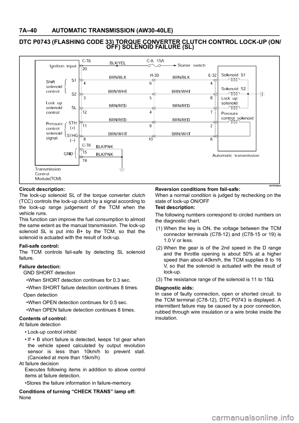
D07RY00047Circuit description:
The lock-up solenoid SL of the torque converter clutch
(TCC) controls the lock-up clutch by a signal according to
the lock-up range judgement of the TCM when the
vehicle runs.
This function can improve the fuel consumption to almost
the same extent as the manual transmission. The lock-up
solenoid SL is put into B+ by the TCM, so that the
solenoid is actuated with the result of lock-up.
Fail-safe control:
The TCM controls fail-safe by detecting SL solenoid
fai lu re.
Failure detection:
GND SHORT detection
•When SHORT detection continues for 0.3 sec.
•When SHORT failure detection continues 8 times.
Open detection
•When OPEN detection continues for 0.5 sec.
•When OPEN failure detection continues 8 times.
Contents of control:
At failure detection
• Lock-up control inhibit
• If + B short failure is detected, keeps 1st gear when
the vehicle speed calculated by output revolution
sensor is less than 10km/h to prevent stall.
(Canceled at more than 15km/h)
At failure decision
Executes following items in addition to above control
items at failure detection.
•Stores the failure information in failure-memory.
Conditions of turning “CHECK TRANS” lamp off:
NoneReversion conditions from fail-safe:
When a normal condition is judged by rechecking on the
state of lock-up ON/OFF
Test description:
The following numbers correspond to circled numbers on
the diagnostic char t.
(1) When the key is ON, the voltage between the TCM
connector terminals (C78-12) and (C78-15 or 19) is
1.0 V or less.
(2) When the gear is of the 2nd speed in the D range
and the throttle opening is about 50% at a higher
speed than about 40km/h, the TCM supplies 8 to 16
V, so that the solenoid is actuated with the result of
lock-up.
(3) The resistance range of the solenoid is 11 to 15
.
Diagnostic aids:
In case of faulty connection, open or shorted circuit. to
the TCM terminal (C78-12), DTC P0743 is displayed. A
intermittent failure may be caused by a poor connection,
rubbed through wire insulation or a wire broke inside the
insulation.