1998 OPEL FRONTERA key
[x] Cancel search: keyPage 4699 of 6000
6E–42
ENGINE DRIVEABILITY AND EMISSIONS
Intermittent Malfunction Indicator Lamp
In the case of an “intermittent” fault, the MIL (“Check
Engine” lamp) may illuminate and then (after three trips)
go “OFF”. However, the corresponding diagnostic trouble
code will be stored in the memory. When unexpected
diagnostic trouble codes appear, check for an intermittent
malfunction.
A diagnostic trouble code may reset. Consult the
“Diagnostic Aids” associated with the diagnostic trouble
code. A physical inspection of the applicable sub-system
most often will resolve the problem.
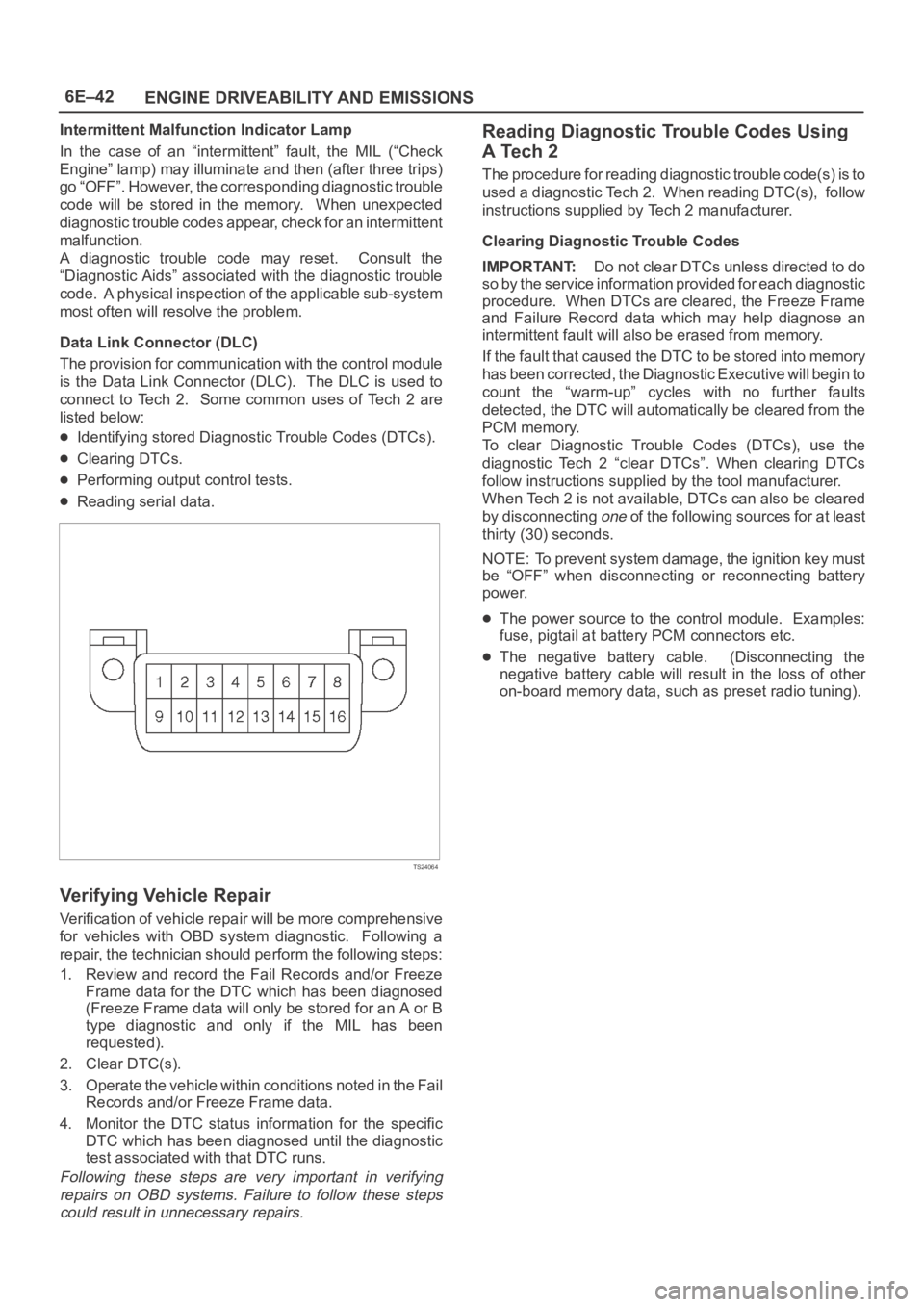
Data Link Connector (DLC)
The provision for communication with the control module
is the Data Link Connector (DLC). The DLC is used to
connect to Tech 2. Some common uses of Tech 2 are
listed below:
Identifying stored Diagnostic Trouble Codes (DTCs).
Clearing DTCs.
Performing output control tests.
Reading serial data.
TS24064
Verifying Vehicle Repair
Verification of vehicle repair will be more comprehensive
for vehicles with OBD system diagnostic. Following a
repair, the technician should perform the following steps:
1. Review and record the Fail Records and/or Freeze
Frame data for the DTC which has been diagnosed
(Freeze Frame data will only be stored for an A or B
type diagnostic and only if the MIL has been
requested).
2. Clear DTC(s).
3. Operate the vehicle within conditions noted in the Fail
Records and/or Freeze Frame data.
4. Monitor the DTC status information for the specific
DTC which has been diagnosed until the diagnostic
test associated with that DTC runs.
Following these steps are very important in verifying
repairs on OBD systems. Failure to follow these steps
could result in unnecessary repairs.
Reading Diagnostic Trouble Codes Using
A Tech 2
The procedure for reading diagnostic trouble code(s) is to
used a diagnostic Tech 2. When reading DTC(s), follow
instructions supplied by Tech 2 manufacturer.
Clearing Diagnostic Trouble Codes
IMPORTANT:Do not clear DTCs unless directed to do
so by the service information provided for each diagnostic
procedure. When DTCs are cleared, the Freeze Frame
and Failure Record data which may help diagnose an
intermittent fault will also be erased from memory.
If the fault that caused the DTC to be stored into memory
has been corrected, the Diagnostic Executive will begin to
count the “warm-up” cycles with no further faults
detected, the DTC will automatically be cleared from the
PCM memory.
To clear Diagnostic Trouble Codes (DTCs), use the
diagnostic Tech 2 “clear DTCs”. When clearing DTCs
follow instructions supplied by the tool manufacturer.
When Tech 2 is not available, DTCs can also be cleared
by disconnecting
one of the following sources for at least
thirty (30) seconds.
NOTE: To prevent system damage, the ignition key must
be “OFF” when disconnecting or reconnecting battery
power.
The power source to the control module. Examples:
fuse, pigtail at battery PCM connectors etc.
The negative battery cable. (Disconnecting the
negative battery cable will result in the loss of other
on-board memory data, such as preset radio tuning).
Page 4700 of 6000
6E–43 ENGINE DRIVEABILITY AND EMISSIONS
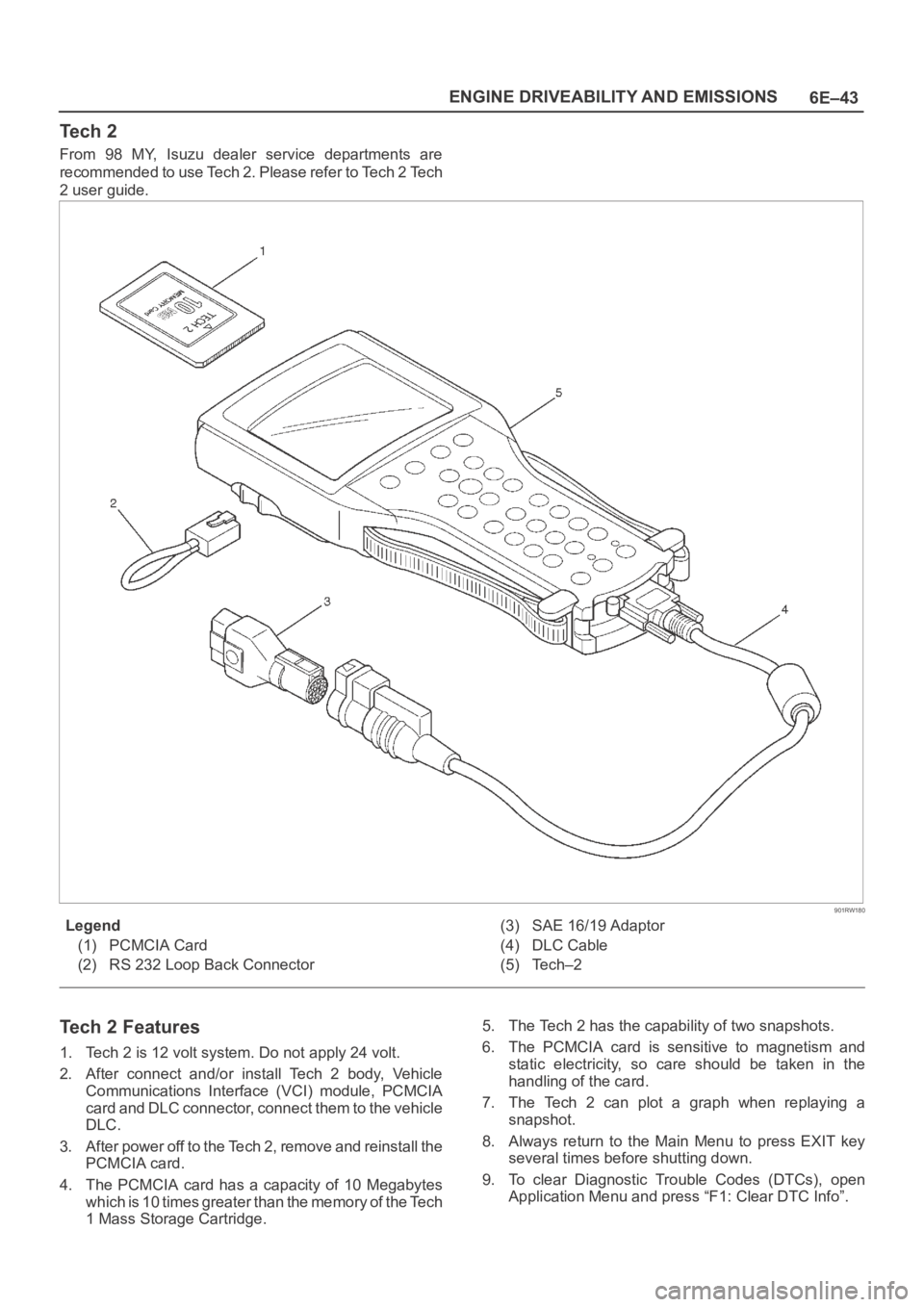
Te c h 2
From 98 MY, Isuzu dealer service departments are
recommended to use Tech 2. Please refer to Tech 2 Tech
2 user guide.
901RW180
Legend
(1) PCMCIA Card
(2) RS 232 Loop Back Connector(3) SAE 16/19 Adaptor
(4) DLC Cable
(5) Tech–2
Tech 2 Features
1. Tech 2 is 12 volt system. Do not apply 24 volt.
2. After connect and/or install Tech 2 body, Vehicle
Communications Interface (VCI) module, PCMCIA
card and DLC connector, connect them to the vehicle
DLC.
3. After power off to the Tech 2, remove and reinstall the
PCMCIA card.
4. The PCMCIA card has a capacity of 10 Megabytes
which is 10 times greater than the memory of the Tech
1 Mass Storage Cartridge.5. The Tech 2 has the capability of two snapshots.
6. The PCMCIA card is sensitive to magnetism and
static electricity, so care should be taken in the
handling of the card.
7. The Tech 2 can plot a graph when replaying a
snapshot.
8. Always return to the Main Menu to press EXIT key
several times before shutting down.
9. To clear Diagnostic Trouble Codes (DTCs), open
Application Menu and press “F1: Clear DTC Info”.
Page 4703 of 6000
6E–46
ENGINE DRIVEABILITY AND EMISSIONS
060RW223
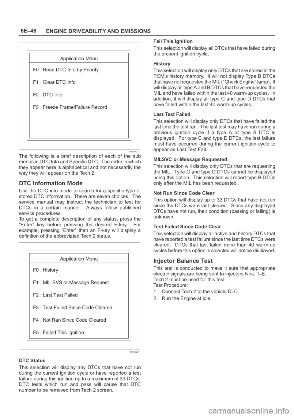
The following is a brief description of each of the sub
menus in DTC Info and Specific DTC. The order in which
they appear here is alphabetical and not necessarily the
way they will appear on the Tech 2.
DTC Information Mode
Use the DTC info mode to search for a specific type of
stored DTC information. There are seven choices. The
service manual may instruct the technician to test for
DTCs in a certain manner. Always follow published
service procedures.
To get a complete description of any status, press the
“Enter” key before pressing the desired F-key. For
example, pressing “Enter” then an F-key will display a
definition of the abbreviated Tech 2 status.
060RW221
DTC Status
This selection will display any DTCs that have not run
during the current ignition cycle or have reported a test
failure during this ignition up to a maximum of 33 DTCs.
DTC tests which run and pass will cause that DTC
number to be removed from Tech 2 screen.Fail This Ignition
This selection will display all DTCs that have failed during
the present ignition cycle.
History
This selection will display only DTCs that are stored in the
PCM’s history memory. It will not display Type B DTCs
that have not requested the MIL (“Check Engine” lamp). It
will display all type A and B DTCs that have requested the
MIL and have failed within the last 40 warm-up cycles. In
addition, it will display all type C and type D DTCs that
have failed within the last 40 warm-up cycles.
Last Test Failed
This selection will display only DTCs that have failed the
last time the test ran. The last test may have run during a
previous ignition cycle if a type A or type B DTC is
displayed. For type C and type D DTCs, the last failure
must have occurred during the current ignition cycle to
appear as Last Test Fail.
MILSVC or Message Requested
This selection will display only DTCs that are requesting
the MIL. Type C and type D DTCs cannot be displayed
using this option. This selection will report type B DTCs
only after the MIL has been requested.
Not Run Since Code Clear
This option will display up to 33 DTCs that have not run
since the DTCs were last cleared. Since any displayed
DTCs have not run, their condition (passing or failing) is
unknown.
Test Failed Since Code Clear
This selection will display all active and history DTCs that
have reported a test failure since the last time DTCs were
cleared. DTCs that last failed more than 40 warm-up
cycles before this option is selected will not be displayed.
Injector Balance Test
This test is conducted to make it sure that appropriate
electric signals are being sent to injectors Nos. 1–6.
Tech 2 must be used for this test.
Test Procedure:
1. Connect Tech 2 to the vehicle DLC.
2. Run the Engine at idle.
Page 4704 of 6000
6E–47 ENGINE DRIVEABILITY AND EMISSIONS
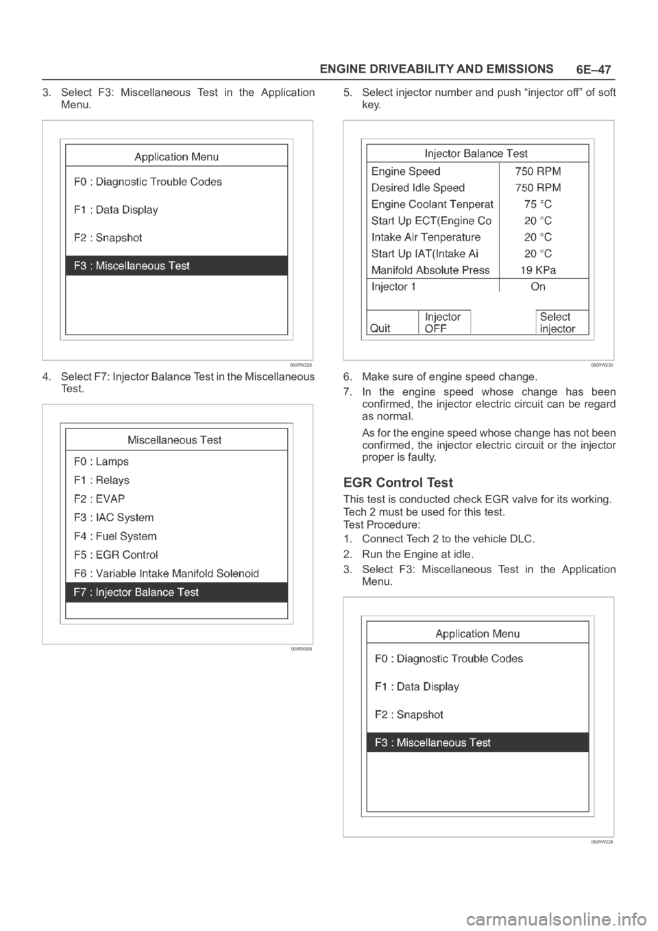
3. Select F3: Miscellaneous Test in the Application
Menu.
060RW228
4. Select F7: Injector Balance Test in the Miscellaneous
Te s t .
060RX006
5. Select injector number and push “injector off” of soft
key.
060RW230
6. Make sure of engine speed change.
7. In the engine speed whose change has been
confirmed, the injector electric circuit can be regard
as normal.
As for the engine speed whose change has not been
confirmed, the injector electric circuit or the injector
proper is faulty.
EGR Control Test
This test is conducted check EGR valve for its working.
Tech 2 must be used for this test.
Test Procedure:
1. Connect Tech 2 to the vehicle DLC.
2. Run the Engine at idle.
3. Select F3: Miscellaneous Test in the Application
Menu.
060RW228
Page 4725 of 6000
6E–68
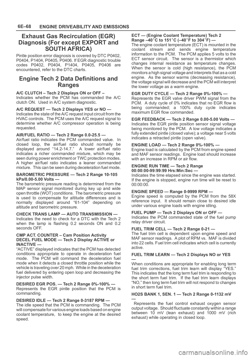
ENGINE DRIVEABILITY AND EMISSIONS
Exhaust Gas Recirculation (EGR)
Diagnosis (For except EXPORT and
SOUTH AFRICA)
Pintle position error diagnosis is covered by DTC P0402,
P0404, P1404, P0405, P0406. If EGR diagnostic trouble
codes P0402, P0404, P1404, P0405, P0406 are
encountered, refer to the DTC charts.
Engine Tech 2 Data Definitions and
Ranges
A/C CLUTCH – Tech 2 Displays ON or OFF –
Indicates whether the PCM has commanded the A/C
clutch ON. Used in A/C system diagnostic.
A/C REQUEST — Tech 2 Displays YES or NO —
Indicates the state of the A/C request input circuit from the
HVAC controls. The PCM uses the A/C request signal to
determine whether A/C compressor operation is being
requested.
AIR/FUEL RATIO — Tech 2 Range 0.0-25.5 —
Air/fuel ratio indicates the PCM commanded value. In
closed loop, the air/fuel ratio should normally be
displayed around “14.2-14.7.” A lower air/fuel ratio
indicates a richer commanded mixture, which may be
seen during power enrichment or TWC protection modes.
A higher air/fuel ratio indicates a leaner commanded
mixture. This can be seen during deceleration fuel mode.
BAROMETRIC PRESSURE — Tech 2 Range 10-105
kPa/0.00-5.00 Volts —
The barometric pressure reading is determined from the
MAP sensor signal monitored during key up and wide
open throttle (WOT) conditions. The barometric pressure
is used to compensate for altitude differences and is
normally displayed around “61-104” depending on
altitude and barometric pressure.
CHECK TRANS LAMP — AUTO TRANSMISSION —
Indicates the need to check for a DTC with the Tech 2
when the lamp is flashing 0.2 seconds ON and 0.2
seconds OFF.
CMP ACT. COUNTER – Cam Position Activity
DECEL FUEL MODE — Tech 2 Display ACTIVE or
INACTIVE —
“ACTIVE” displayed indicates that the PCM has detected
conditions appropriate to operate in deceleration fuel
mode. The PCM will command the deceleration fuel
mode when it detects a closed throttle position while the
vehicle is traveling over 20 mph. While in the deceleration
fuel delivered by entering open loop and decreasing the
injector pulse width.
DESIRED EGR POS. — Tech 2 Range 0%-100% —
Represents the EGR pintle position that the PCM is
commanding.
DESIRED IDLE — Tech 2 Range 0-3187 RPM —
The idle speed that the PCM is commanding. The PCM
will compensate for various engine loads based on engine
coolant temperature, to keep the engine at the desired
speed.ECT — (Engine Coolant Temperature) Tech 2
Range –40
C to 151C (–40F to 304F) —
The engine coolant temperature (ECT) is mounted in the
coolant stream and sends engine temperature
information to the PCM. The PCM applies 5 volts to the
ECT sensor circuit. The sensor is a thermistor which
changes internal resistance as temperature changes.
When the sensor is cold (high resistance), the PCM
monitors a high signal voltage and interprets that as a cold
engine. As the sensor warms (decreasing resistance),
the voltage signal will decrease and the PCM will interpret
the lower voltage as a warm engine.
EGR DUTY CYCLE — Tech 2 Range 0%-100% —
Represents the EGR valve driver PWM signal from the
PCM. A duty cycle of 0% indicates that no EGR flow is
being commanded; a 100% duty cycle indicates
maximum EGR flow commanded.
EGR FEEDBACK — Tech 2 Range 0.00-5.00 Volts —
Indicates the EGR pintle position sensor signal voltage
being monitored by the PCM. A low voltage indicates a
fully extended pintle (closed valve); a voltage near 5 volts
indicates a retracted pintle (open valve).
ENGINE LOAD — Tech 2 Range 0%-100% —
Engine load is calculated by the PCM from engine speed
and MAF sensor readings. Engine load should increase
with an increase in RPM or air flow.
ENGINE RUN TIME — Tech 2 Range
00:00:00-99:99:99 Hrs:Min:Sec —
Indicates the time elapsed since the engine was started.
If the engine is stopped, engine run time will be reset to
00:00:00.
ENGINE SPEED — Range 0-9999 RPM —
Engine speed is computed by the PCM from the 58X
reference input. It should remain close to desired idle
under various engine loads with engine idling.
FUEL PUMP — Tech 2 Displays ON or OFF —
Indicates the PCM commanded state of the fuel pump
relay driver circuit.
FUEL TRIM CELL — Tech 2 Range 0-21 —
The fuel trim cell is dependent upon engine speed and
MAF sensor readings. A plot of RPM vs. MAF is divided
into 22 cells. Fuel trim cell indicates which cell is currently
active.
FUEL TRIM LEARN — Tech 2 Displays NO or YES
—
When conditions are appropriate for enabling long term
fuel trim corrections, fuel trim learn will display “YES.”
This indicates that the long term fuel trim is responding to
the short term fuel trim. If the fuel trim learn displays
“NO,” then long term fuel trim will not respond to changes
in short term fuel trim.
HO2S BANK 1, SEN. 1 — Tech 2 Range 0-1132 mV
—
Represents the fuel control exhaust oxygen sensor
output voltage. Should fluctuate constantly within a range
between 10 mV (lean exhaust) and 1000 mV (rich
exhaust) while operating in closed loop.
Page 4772 of 6000
6E–115 ENGINE DRIVEABILITY AND EMISSIONS
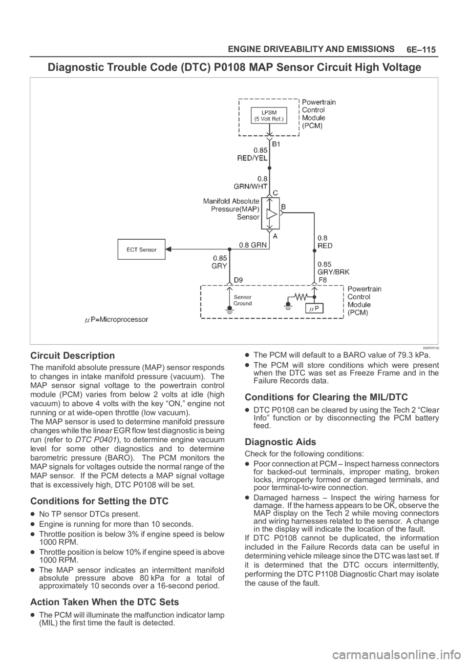
Diagnostic Trouble Code (DTC) P0108 MAP Sensor Circuit High Voltage
D06RW102
Circuit Description
The manifold absolute pressure (MAP) sensor responds
to changes in intake manifold pressure (vacuum). The
MAP sensor signal voltage to the powertrain control
module (PCM) varies from below 2 volts at idle (high
vacuum) to above 4 volts with the key “ON,” engine not
running or at wide-open throttle (low vacuum).
The MAP sensor is used to determine manifold pressure
changes while the linear EGR flow test diagnostic is being
run (refer to
DTC P0401), to determine engine vacuum
level for some other diagnostics and to determine
barometric pressure (BARO). The PCM monitors the
MAP signals for voltages outside the normal range of the
MAP sensor. If the PCM detects a MAP signal voltage
that is excessively high, DTC P0108 will be set.
Conditions for Setting the DTC
No TP sensor DTCs present.
Engine is running for more than 10 seconds.
Throttle position is below 3% if engine speed is below
1000 RPM.
Throttle position is below 10% if engine speed is above
1000 RPM.
The MAP sensor indicates an intermittent manifold
absolute pressure above 80kPa for a total of
approximately 10 seconds over a 16-second period.
Action Taken When the DTC Sets
The PCM will illuminate the malfunction indicator lamp
(MIL) the first time the fault is detected.
The PCM will default to a BARO value of 79.3 kPa.
The PCM will store conditions which were present
when the DTC was set as Freeze Frame and in the
Failure Records data.
Conditions for Clearing the MIL/DTC
DTC P0108 can be cleared by using the Tech 2 “Clear
Info” function or by disconnecting the PCM battery
feed.
Diagnostic Aids
Check for the following conditions:
Poor connection at PCM – Inspect harness connectors
for backed-out terminals, improper mating, broken
locks, improperly formed or damaged terminals, and
poor terminal-to-wire connection.
Damaged harness – Inspect the wiring harness for
damage. If the harness appears to be OK, observe the
MAP display on the Tech 2 while moving connectors
and wiring harnesses related to the sensor. A change
in the display will indicate the location of the fault.
If DTC P0108 cannot be duplicated, the information
included in the Failure Records data can be useful in
determining vehicle mileage since the DTC was last set. If
it is determined that the DTC occurs intermittently,
performing the DTC P1108 Diagnostic Chart may isolate
the cause of the fault.
Page 4793 of 6000
6E–136
ENGINE DRIVEABILITY AND EMISSIONS
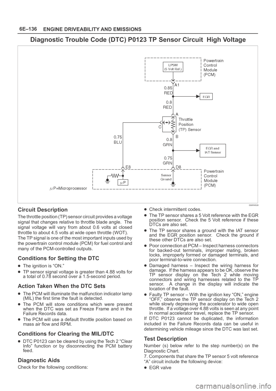
Diagnostic Trouble Code (DTC) P0123 TP Sensor Circuit High Voltage
D06RW028
Circuit Description
The throttle position (TP) sensor circuit provides a voltage
signal that changes relative to throttle blade angle. The
signal voltage will vary from about 0.6 volts at closed
throttle to about 4.5 volts at wide open throttle (WOT).
The TP signal is one of the most important inputs used by
the powertrain control module (PCM) for fuel control and
many of the PCM-controlled outputs.
Conditions for Setting the DTC
The ignition is “ON.”
TP sensor signal voltage is greater than 4.88 volts for
a total of 0.78 second over a 1.5-second period.
Action Taken When the DTC Sets
The PCM will illuminate the malfunction indicator lamp
(MIL) the first time the fault is detected.
The PCM will store conditions which were present
when the DTC was set as Freeze Frame and in the
Failure Records data.
The PCM will use a default throttle position based on
mass air flow and RPM.
Conditions for Clearing the MIL/DTC
DTC P0123 can be cleared by using the Tech 2 “Clear
Info” function or by disconnecting the PCM battery
feed.
Diagnostic Aids
Check for the following conditions:
Check intermittent codes.
The TP sensor shares a 5 Volt reference with the EGR
position sensor. Check the 5 Volt reference if these
DTCs are also set.
The TP sensor shares a ground with the IAT sensor
and the EGR position sensor. Check the ground if
these other DTCs are also set.
Poor connection at PCM – Inspect harness connectors
for backed-out terminals, improper mating, broken
locks, improperly formed or damaged terminals, and
poor terminal-to-wire connection.
Damaged harness – Inspect the wiring harness for
damage. If the harness appears to be OK, observe the
TP sensor display on the Tech 2 while moving
connectors and wiring harnesses related to the TP
sensor. A change in the display will indicate the
location of the fault.
Faulty TP sensor – With the ignition key “ON,” engine
“OFF,” observe the TP sensor display on the Tech 2
while slowly depressing the accelerator to wide open
throttle. If a voltage over 4.88 volts is seen at any point
in normal accelerator travel, replace the TP sensor.
If DTC P0123 cannot be duplicated, the information
included in the Failure Records data can be useful in
determining vehicle mileage since the DTC was last set.
Test Description
Number (s) below refer to the step number(s) on the
Diagnostic Chart.
7. Components that share the TP sensor 5 volt reference
“A” circuit include the following device:
EGR valve
Page 4800 of 6000
6E–143 ENGINE DRIVEABILITY AND EMISSIONS
An intermittent TP sensor output will cause the system
to go rich due to a false indication of the engine
accelerating.
Shorted Heated Oxygen Sensor (HO2S) –If the HO2S
is internally shorted, the HO2S voltage displayed on
the Tech 2 will be over 1 volt. Try disconnecting the
affected HO2S with the key “ON,” engine “OFF.” If the
displayed HO2S voltage changes from over 1000 mV
to around 450 mV, replace the HO2S. Silicon
contamination of the HO2S can also cause a high
HO2S voltage to be indicated. This condition is
indicated by a powdery white deposit on the portion of
the HO2S exposed to the exhaust stream. If
contamination is noticed, replace the affected HO2S.
Open HO2S Signal Circuit or Faulty HO2S–A poor
connection or open in the HO2S signal circuit can
cause the DTC to set during deceleration fuel mode.
A n H O 2 S w h i c h i s f a u l t y a n d n o t a l l o w i n g a f u l l v o l t a g e
swing between the rich and lean thresholds can also
cause this condition. Operate the vehicle by
monitoring the HO2S voltage with a Tech 2. If theHO2S voltage is limited within a range between 300
mV to 600 mV, check the HO2S signal circuit wiring
and associated terminal conditions.
If none of the above conditions are present, replace the
affected HO2S.
Test Description
Number(s) below refer to the step number(s) on the
Diagnostic Chart.
3. DTC P0132 failing during “deceleration fuel cutoff
mode” operation may indicate a condition described
in the “Diagnostic Aids” above. If the DTC P0132
test passes while the Failure Records conditions are
being duplicated, an intermittent condition is
indicated.
Reviewing the Failure Records vehicle mileage since the
diagnostic test last failed may help determine how often
the condition that caused the DTC to be set occurs. This
may assist in diagnosing the condition.
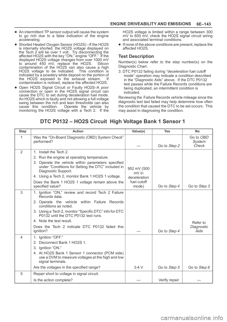
DTC P0132 – HO2S Circuit High Voltage Bank 1 Sensor 1
StepActionVa l u e ( s )Ye sNo
1Was the “On-Board Diagnostic (OBD) System Check”
performed?
—Go to Step 2
Go to OBD
System
Check
21. Install the Tech 2.
2. Run the engine at operating temperature.
3. Operate the vehicle within parameters specified
under “Conditions for Setting the DTC” included in
Diagnostic Support.
4. Using a Tech 2, monitor Bank 1 HO2S 1 voltage.
Does the Bank 1 HO2S 1 voltage remain above the
specified value?
952 mV (500
mV in
deceleration
fuel cutoff
mode)
Go to Step 4Go to Step 3
31. Ignition “ON,” review and record Tech 2 Failure
Records data.
2. Operate the vehicle within Failure Records
conditions as noted.
3. Using a Tech 2, monitor “Specific DTC” info for DTC
P0132 until the DTC P0132 test runs.
4. Note the test result.
Does the Tech 2 indicate DTC P0132 failed this
ignition?
—Go to Step 4
Refer to
Diagnostic
Aids
41. Ignition “OFF.”
2. Disconnect Bank 1 HO2S 1.
3. Ignition “ON.”
4. At HO2S Bank 1 Sensor 1 connector (PCM side)
use a DVM to measure voltages at the high and low
signal terminals.
Are the voltages in the specified range?
3-4 VGo to Step 5Go to Step 6
5Repair short to voltage in signal circuit.
Is the action complete?
—Verify repair—