1998 OPEL FRONTERA key
[x] Cancel search: keyPage 5826 of 6000

AUTOMATIC TRANSMISSION (AW30-40LE) 7A–45
• Changes solenoid output pattern as following figure
The shift theory at shift solenoid failure
At failure decision
Executes following items in addition to above control
items at failure detection.
•Turns Solenoid power supply OFF
•Blinks "CHECK TRANS" lamp
•Stores the failure information in failure-memory
*Prohibits failure detection of S1, S2, SL, STH,
Selector position switch, and Oil temp. sensor.
Conditions of turning "CHECK TRANS" off:
Turns "CHECK TRANS" lamp off after ignition is turned
ON
OFF ON.
Reversion conditions from fail-safe:
At failure detection
When a normal judgment is obtained by rechecking
during shifting.
At failure decision
Recovers at the same time as the conditions of
turning “CHECK TRANS” lamp off are satisfied.
Test description:
The following numbers correspond to circled numbers on
the diagnostic char t.
(1) With the key "ON", the voltage between the TCM
terminals (C78-4) and (C78-15 or 19) is 8 to 16V.
(2) When the driving wheels revolve with the 3rd speed
gear, the voltage is 1 V or less.
(3) The solenoid resistance is within the range of 11 to
15
.
Diagnostic aids:
In case of faulty connection, open or shor ted circuit to
the TCM terminal (C78-4), DTC P0753 is displayed. A
intermittent failure may be caused by a poor connection,
rubbed through wire insulation or a wire broke inside the
insulation.Shift
lever
Po s i t i o nNormal S1 failure S2 filure S1 and S2 failure
Gear S1 S2 Gear S1 S2 Gear S1 S2 Gear S1 S2
D1
3
1
O/D 2O/D3
O/DO/D
213
1
3 2O/D3
L1313
2O/D
Page 5829 of 6000

7A–48 AUTOMATIC TRANSMISSION (AW30-40LE)
DTC P0758 (FLASHING CODE 32) SOLENOID 2 FAILURE (S2)
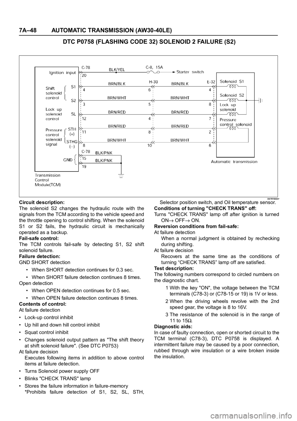
D07RY00047Circuit description:
The solenoid S2 changes the hydraulic route with the
signals from the TCM according to the vehicle speed and
the throttle opening to control shifting. When the solenoid
S1 or S2 fails, the hydraulic circuit is mechanically
operated as a backup.
Fail-safe control:
The TCM controls fail-safe by detecting S1, S2 shift
solenoid failure.
Failure detection:
GND SHORT detection
• When SHORT detection continues for 0.3 sec.
• When SHORT failure detection continues 8 times.
Open detection
• When OPEN detection continues for 0.5 sec.
• When OPEN failure detection continues 8 times.
Contents of control:
At failure detection
• Lock-up control inhibit
• Up hill and down hill control inhibit
• Squat control inhibit
• Changes solenoid output pattern as "The shift theory
at shift solenoid failure". (See DTC P0753)
At failure decision
Executes following items in addition to above control
items at failure detection.
• Turns Solenoid power supply OFF
• Blinks "CHECK TRANS" lamp
• Stores the failure information in failure-memory
*Prohibits failure detection of S1, S2, SL, STH,Selector position switch, and Oil temperature sensor.
Conditions of turning "CHECK TRANS" off:
Turns "CHECK TRANS" lamp off after ignition is turned
ON
OFF ON.
Reversion conditions from fail-safe:
At failure detection
When a normal judgment is obtained by rechecking
during shifting.
At failure decision
Recovers at the same time as the conditions of
turning “CHECK TRANS” lamp off are satisfied.
Test description:
The following numbers correspond to circled numbers on
the diagnostic char t.
1 With the key "ON", the voltage between the TCM
terminals (C78-3) or (C78-15 or 19) is 1V or less.
2 When the driving wheels revolve with the 2nd
speed gear, the voltage is 8 to 16V.
3 The resistance of the solenoid is in the range of
11 to 15
.
Diagnostic aids:
In case of faulty connection, open or shor ted circuit to the
TCM terminal (C78-3), DTC P0758 is displayed. A
intermittent failure may be caused by a poor connection,
rubbed through wire insulation or a wire broken inside
the insulation.
Page 5853 of 6000

7A–72 AUTOMATIC TRANSMISSION (AW30-40LE)
TCM STANDARD VOLTAGE
Check circuitTe r m i n a l
Measuring condition Voltage (V)
+-
Throttle position sensorC79-6 C79-28Throttle fully opened (WOT) 3.47
4.56
Throttle fully closed (idling) 0.25
0.45
C79-19 C79-18 Key switch ON 4.75
5.25
Output revolution sensor C79-4 C79-16 Engine idling in gear 0
3
Input revolution sensor C79-5 C79-17 Engine idling 0
3
Speed meter sensor C79-7C78-15
or -19Vehicle speed 10
20 km/h Less than 1.4
about 5
Brake switch C78-18C78-15
or -19Depress brake 7
16
Release brake Less than 1
O/D OFF switch C79-3C78-15
or -19O/D OFF switch ON (O/D OFF) 7
16
O/D OFF switch OFF (O/D ON) Less than 1
Neutral start switch
C79-2C78-15
or -19Selector “P” range 7
16
(P) Selector all ranges except “P” Less than 1
Neutral start switch
C79-1C78-15
or -19Selector “R” range 7
16
(R) Selector all ranges except “R” Less than 1
Neutral start switch
C79-9C78-15
or -19Selector “N” range 7
16
(N) Selector all ranges except “N” Less than 1
Neutral start switch
C79-8C78-15
or -19Selector “D” range 7
16
(D) Selector all ranges except “D” Less than 1
Neutral start switch
C79-21C78-15
or -19Selector “2” range 7
16
(2) Selector all ranges except “2” Less than 1
Neutral start switch
C79-20C78-15
or -19Selector “L” range 7
16
(L) Selector all ranges except “L” Less than 1
Engine revolution signal C79-15C78-15
or -19Engine idling Less than 1.4
9 16
Diagnosis terminal C79-24C78-15
or -19Self-diagnosis ON
0
1.5
Power pattern switch C79-23C78-15
or -19Power pattern switch OFF (NORMAL) 8
16
Power pattern switch ON (POWER) Less than 1.4
Winter select switch C79-13C78-15
or -19Switch OFF 8
16
Switch ON Less than 1.4
Electrical source (Battery) C78-13C78-15
or -19—
9
16
Electrical source (Ignition) C78-20C78-15
or -19Key switch ON
9
16
Oil temperature warning lamp C79-11C78-15
or -19Oil temperature warning lamp ON Less than 1
Oil temperature warning lamp OFF 8
16
“CHECK TRANS lamp” C79-10C78-15
or -19“CHECK TRANS” lamp ON Less than 1
“CHECK TRANS” lamp OFF 8
16
Power lamp C79-22C78-15
or -19Power lamp ON Less than 1
Powe r l a m p O F F 8
16
Page 5854 of 6000

AUTOMATIC TRANSMISSION (AW30-40LE) 7A–73
Check circuitTe r m i n a l
Measuring condition Voltage (V)
+-
Winter lamp C79-12C78-15
or -19Winter lamp ON Less than 1
Winter lamp OFF 8
16
Solenoid S1 C78-4C78-15
or -19OFF (3rd or O/D) Less than 1
ON (1st or 2nd) 8
16
Solenoid S2 C78-3C78-15
or -19OFF (1st or O/D) Less than 1
ON (2nd or 3rd) 8
16
Lock up solenoid SL C78-12C78-15
or -19OFF (Lock up OFF) Less than 1
ON (Lock up ON) 8
16
Pressure control solenoid C78-11 C78-8At throttle pressure changing Less than
1
8-16
Oil temperature sensor C79-18 C79-27ATF temperature 20
C4.70
ATF temperature 80
C3.65
Tech 2 diagnosis terminal
(J1850)C78-6C78-15
or -19On diagnosis communication 0-1.5
6.25-8.0
Throttle position sensor
(ground)C79-19C78-15
or -19Key switch ON
-0.1
0.1
Page 5862 of 6000

AUTOMATIC TRANSMISSION (AW30-40LE) 7A–81
256RW014
256RW015
INSTALLATION
To install, follow the removal steps in the reverse order, noting
the following points;
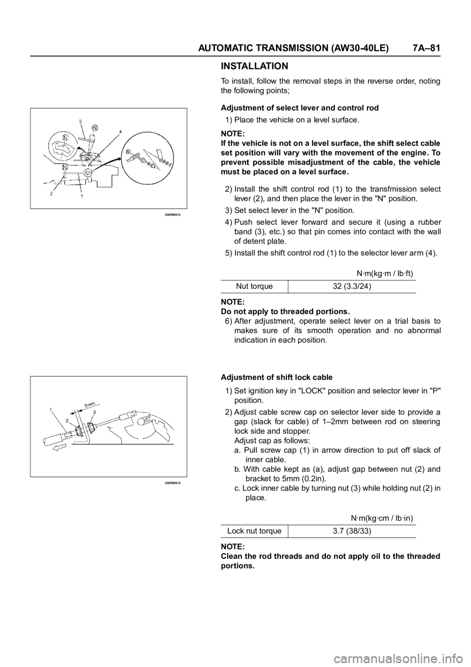
Adjustment of select lever and control rod
1) Place the vehicle on a level surface.
NOTE:
If the vehicle is not on a level surface, the shift select cable
set position will vary with the movement of the engine. To
prevent possible misadjustment of the cable, the vehicle
must be placed on a level surface.
2) Install the shift control rod (1) to the transfmission select
lever (2), and then place the lever in the "N" position.
3) Set select lever in the "N" position.
4) Push select lever forward and secure it (using a rubber
band (3), etc.) so that pin comes into contact with the wall
of detent plate.
5) Install the shift control rod (1) to the selector lever arm (4).
NOTE:
Do not apply to threaded portions.
6) After adjustment, operate select lever on a trial basis to
makes sure of its smooth operation and no abnormal
indication in each position.
Adjustment of shift lock cable
1) Set ignition key in "LOCK" position and selector lever in "P"
position.
2) Adjust cable screw cap on selector lever side to provide a
gap (slack for cable) of 1–2mm between rod on steering
lock side and stopper.
Adjust cap as follows:
a. Pull screw cap (1) in arrow direction to put off slack of
inner cable.
b. With cable kept as (a), adjust gap between nut (2) and
bracket to 5mm (0.2in).
c. Lock inner cable by tur ning nut (3) while holding nut (2) in
place.
NOTE:
Clean the rod threads and do not apply oil to the threaded
portions.Nꞏm(kgꞏm / lbꞏft)
Nut torque 32 (3.3/24)
Nꞏm(kgꞏcm / lbꞏin)
Lock nut torque 3.7 (38/33)
Page 5863 of 6000

7A–82 AUTOMATIC TRANSMISSION (AW30-40LE)
3) Make sure of proper operation of shift lock through checks
as follows:
a. Selector lever shall not be moved out of "P" position with
ingition key in "Lock" position.
b. Selector lever can be moved out of "P" position with
ignition key in "ON" position only when brake pedal is
depressed.
c. Ignition key can be turned to "LOCK" position only when
selector lever is in "P" position (key can be pulled out).
If (a) and (c) fail, readjust cable. If (b) fails, readjust
connector wiring and brake pedal switch.