1998 OPEL FRONTERA key
[x] Cancel search: keyPage 3363 of 6000
8H–24SECURITY AND LOCKS
Keyless Entry System
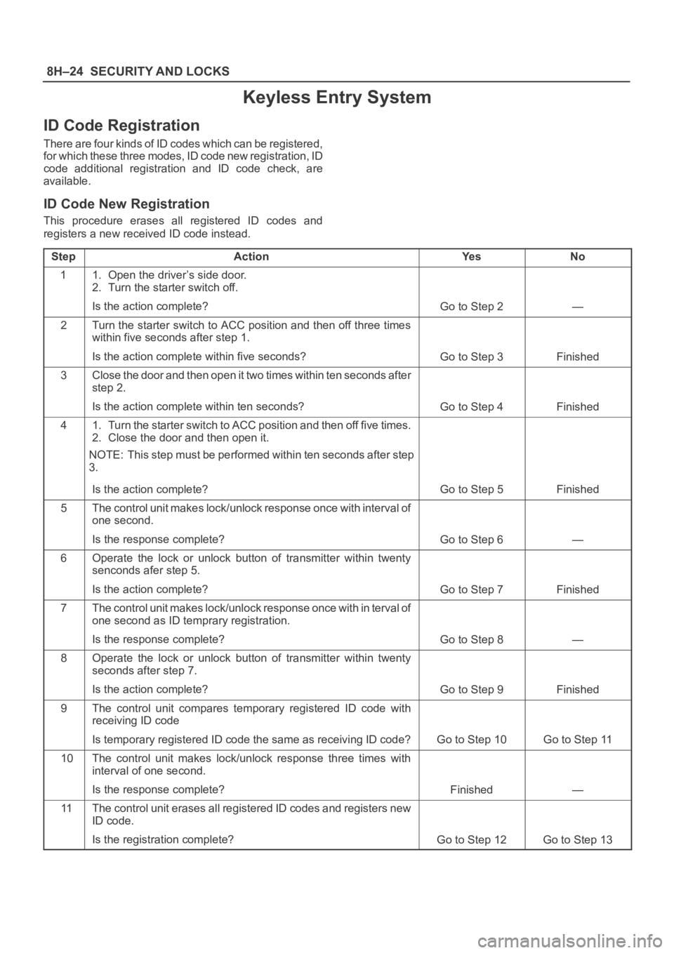
ID Code Registration
There are four kinds of ID codes which can be registered,
for which these three modes, ID code new registration, ID
code additional registration and ID code check, are
available.
ID Code New Registration
This procedure erases all registered ID codes and
registers a new received ID code instead.
Step
ActionYe sNo
11. Open the driver’s side door.
2. Turn the starter switch off.
Is the action complete?
Go to Step 2—
2Turn the starter switch to ACC position and then off three times
within five seconds after step 1.
Is the action complete within five seconds?
Go to Step 3Finished
3Close the door and then open it two times within ten seconds after
step 2.
Is the action complete within ten seconds?
Go to Step 4Finished
41. Turn the starter switch to ACC position and then off five times.
2. Close the door and then open it.
NOTE: This step must be performed within ten seconds after step
3.
Is the action complete?
Go to Step 5Finished
5The control unit makes lock/unlock response once with interval of
one second.
Is the response complete?
Go to Step 6—
6Operate the lock or unlock button of transmitter within twenty
senconds afer step 5.
Is the action complete?
Go to Step 7Finished
7The control unit makes lock/unlock response once with in terval o f
one second as ID temprary registration.
Is the response complete?
Go to Step 8—
8Operate the lock or unlock button of transmitter within twenty
seconds after step 7.
Is the action complete?
Go to Step 9Finished
9The control unit compares temporary registered ID code with
receiving ID code
Is temporary registered ID code the same as receiving ID code?
Go to Step 10Go to Step 11
10The control unit makes lock/unlock response three times with
interval of one second.
Is the response complete?
Finished—
11The control unit erases all registered ID codes and registers new
ID code.
Is the registration complete?
Go to Step 12Go to Step 13
Page 3366 of 6000
SECURITY AND LOCKS8H–27
StepNo Ye s Action
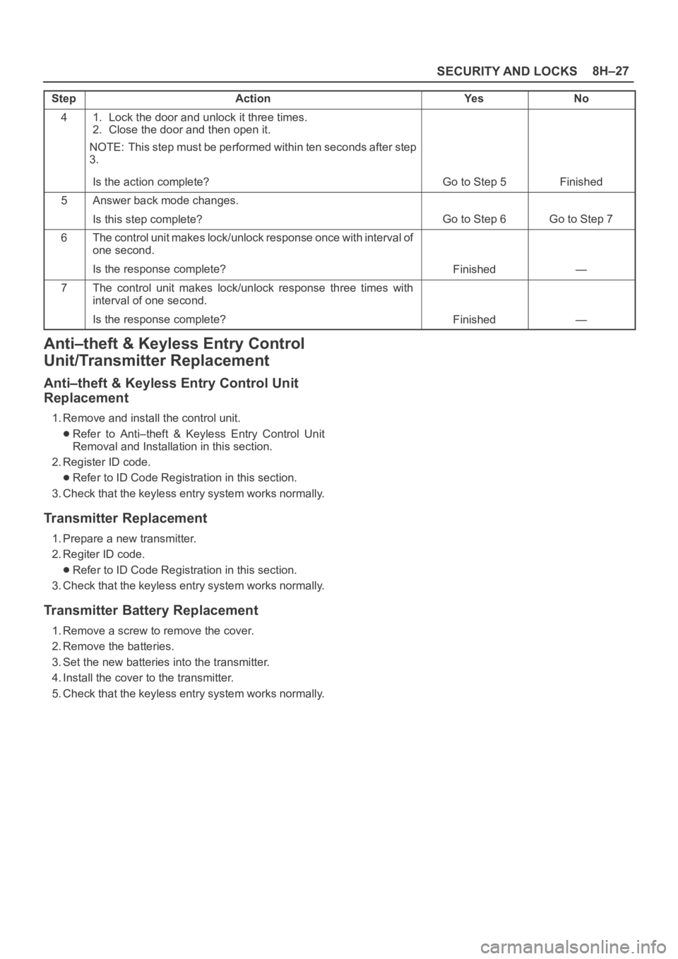
41. Lock the door and unlock it three times.
2. Close the door and then open it.
NOTE: This step must be performed within ten seconds after step
3.
Is the action complete?
Go to Step 5Finished
5Answer back mode changes.
Is this step complete?
Go to Step 6Go to Step 7
6The control unit makes lock/unlock response once with interval of
one second.
Is the response complete?
Finished—
7The control unit makes lock/unlock response three times with
interval of one second.
Is the response complete?
Finished—
Anti–theft & Keyless Entry Control
Unit/Transmitter Replacement
Anti–theft & Keyless Entry Control Unit
Replacement
1. Remove and install the control unit.
Refer to Anti–theft & Keyless Entry Control Unit
Removal and Installation in this section.
2. Register ID code.
Refer to ID Code Registration in this section.
3. Check that the keyless entry system works normally.
Transmitter Replacement
1. Prepare a new transmitter.
2. Regiter ID code.
Refer to ID Code Registration in this section.
3. Check that the keyless entry system works normally.
Transmitter Battery Replacement
1. Remove a screw to remove the cover.
2. Remove the batteries.
3. Set the new batteries into the transmitter.
4. Install the cover to the transmitter.
5. Check that the keyless entry system works normally.
Page 3367 of 6000

8H–28SECURITY AND LOCKS
Main Data and Specifications
Torque Specifications
ApplicationNꞏmKgꞏmLb FtLb In
Front Door Lock Assembly Fixing Screws70.7—61
Front Outside Handle and Key Switch Fixing Bolts90.9—78
Rear Door Lock Assembly Fixing Screws70.7—61
Rear Outside Handle Fixing Bolts90.9—78
Tailgate Lock Assembly (LH) Fixing Screws70.7—61
Tailgate Lock Assembly (RH) Fixing Bolts111.1—95
Tailgate Outside Handle and Key Cylinder Fixing Bolts90.9—78
Page 3442 of 6000
SUPPLEMENTAL RESTRAINT SYSTEM9J–5
1. Energy Reserve — The SDM maintains 24–Volt Loop
Reserve (24VLR) energy supply to provide
deployment energy when ignition voltage is lost in a
frontal crash.
2. Frontal Crash Detection — The SDM monitors
vehicle velocity changes to detect frontal crashes
which are severe enough to warrant deployment.
3. Air Bag Deployment — When a frontal crash of
sufficient force is detected, the SDM will cause
enough current to flow through the air bag assembly
to deploy the air bag.
4. Malfunction Detection — The SDM performs
diagnostic monitoring of SRS electrical components
and sets a diagnostic trouble code when a
malfunction is detected.
5. Frontal Crash Recording — The SDM records
information regarding SRS status during frontal
crash.
6. Malfunction Diagnosis — The SDM displays SRS
diagnostic trouble codes and system status
information through the use of a scan tool.
7. Driver Notification — The SDM warns the vehicle
driver of SRS malfunctions by controlling the “Air
Bag” warning lamp.
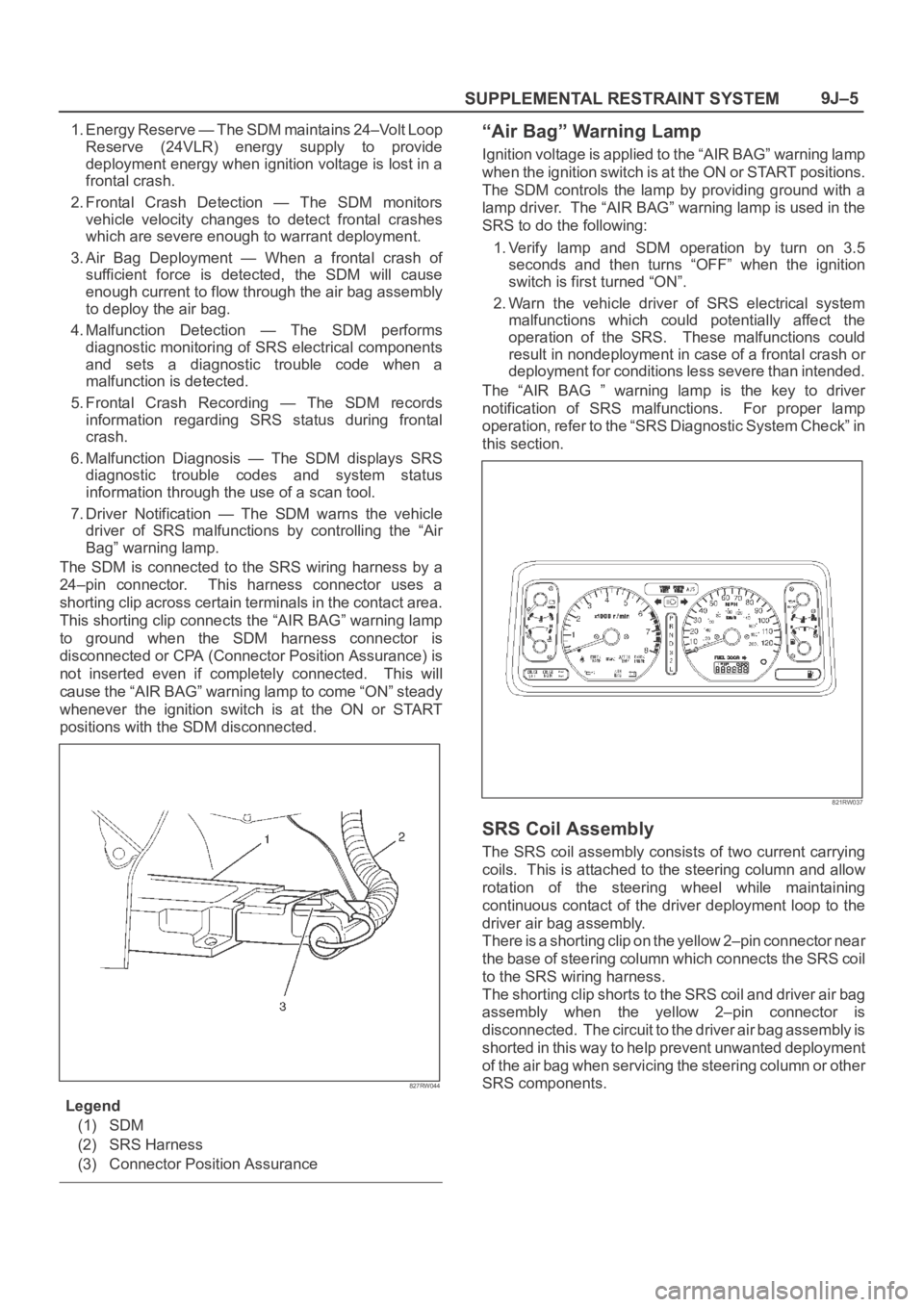
The SDM is connected to the SRS wiring harness by a
24–pin connector. This harness connector uses a
shorting clip across certain terminals in the contact area.
This shorting clip connects the “AIR BAG” warning lamp
to ground when the SDM harness connector is
disconnected or CPA (Connector Position Assurance) is
not inserted even if completely connected. This will
cause the “AIR BAG” warning lamp to come “ON” steady
whenever the ignition switch is at the ON or START
positions with the SDM disconnected.
827RW044
Legend
(1) SDM
(2) SRS Harness
(3) Connector Position Assurance
“Air Bag” Warning Lamp
Ignition voltage is applied to the “AIR BAG” warning lamp
when the ignition switch is at the ON or START positions.
The SDM controls the lamp by providing ground with a
lamp driver. The “AIR BAG” warning lamp is used in the
SRS to do the following:
1. Verify lamp and SDM operation by turn on 3.5
seconds and then turns “OFF” when the ignition
switch is first turned “ON”.
2. Warn the vehicle driver of SRS electrical system
malfunctions which could potentially affect the
operation of the SRS. These malfunctions could
result in nondeployment in case of a frontal crash or
deployment for conditions less severe than intended.
The “AIR BAG ” warning lamp is the key to driver
notification of SRS malfunctions. For proper lamp
operation, refer to the “SRS Diagnostic System Check” in
this section.
821RW037
SRS Coil Assembly
The SRS coil assembly consists of two current carrying
coils. This is attached to the steering column and allow
rotation of the steering wheel while maintaining
continuous contact of the driver deployment loop to the
driver air bag assembly.
There is a shorting clip on the yellow 2–pin connector near
the base of steering column which connects the SRS coil
to the SRS wiring harness.
The shorting clip shorts to the SRS coil and driver air bag
assembly when the yellow 2–pin connector is
disconnected. The circuit to the driver air bag assembly is
shorted in this way to help prevent unwanted deployment
of the air bag when servicing the steering column or other
SRS components.
Page 3444 of 6000
SUPPLEMENTAL RESTRAINT SYSTEM9J–7
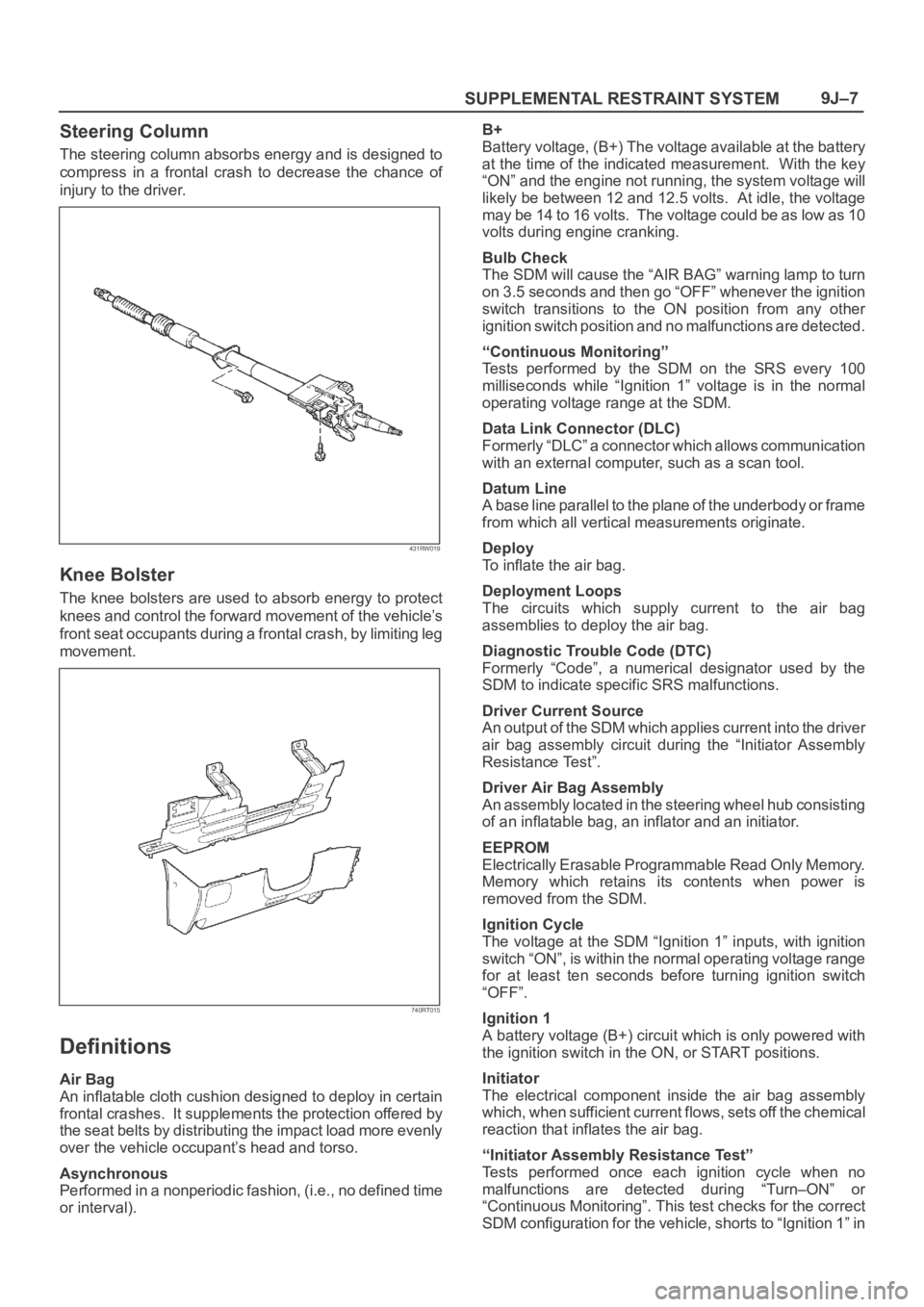
Steering Column
The steering column absorbs energy and is designed to
compress in a frontal crash to decrease the chance of
injury to the driver.
431RW019
Knee Bolster
The knee bolsters are used to absorb energy to protect
knees and control the forward movement of the vehicle’s
front seat occupants during a frontal crash, by limiting leg
movement.
740RT015
Definitions
Air Bag
An inflatable cloth cushion designed to deploy in certain
frontal crashes. It supplements the protection offered by
the seat belts by distributing the impact load more evenly
over the vehicle occupant’s head and torso.
Asynchronous
Performed in a nonperiodic fashion, (i.e., no defined time
or interval).B+
Battery voltage, (B+) The voltage available at the battery
at the time of the indicated measurement. With the key
“ON” and the engine not running, the system voltage will
likely be between 12 and 12.5 volts. At idle, the voltage
may be 14 to 16 volts. The voltage could be as low as 10
volts during engine cranking.
Bulb Check
The SDM will cause the “AIR BAG” warning lamp to turn
on 3.5 seconds and then go “OFF” whenever the ignition
switch transitions to the ON position from any other
ignition switch position and no malfunctions are detected.
“Continuous Monitoring”
Tests performed by the SDM on the SRS every 100
milliseconds while “Ignition 1” voltage is in the normal
operating voltage range at the SDM.
Data Link Connector (DLC)
Formerly “DLC” a connector which allows communication
with an external computer, such as a scan tool.
Datum Line
A base line parallel to the plane of the underbody or frame
from which all vertical measurements originate.
Deploy
To inflate the air bag.
Deployment Loops
The circuits which supply current to the air bag
assemblies to deploy the air bag.
Diagnostic Trouble Code (DTC)
Formerly “Code”, a numerical designator used by the
SDM to indicate specific SRS malfunctions.
Driver Current Source
An output of the SDM which applies current into the driver
air bag assembly circuit during the “Initiator Assembly
Resistance Test”.
Driver Air Bag Assembly
An assembly located in the steering wheel hub consisting
of an inflatable bag, an inflator and an initiator.
EEPROM
Electrically Erasable Programmable Read Only Memory.
Memory which retains its contents when power is
removed from the SDM.
Ignition Cycle
The voltage at the SDM “Ignition 1” inputs, with ignition
switch “ON”, is within the normal operating voltage range
for at least ten seconds before turning ignition switch
“OFF”.
Ignition 1
A battery voltage (B+) circuit which is only powered with
the ignition switch in the ON, or START positions.
Initiator
The electrical component inside the air bag assembly
which, when sufficient current flows, sets off the chemical
reaction that inflates the air bag.
“Initiator Assembly Resistance Test”
Tests performed once each ignition cycle when no
malfunctions are detected during “Turn–ON” or
“Continuous Monitoring”. This test checks for the correct
SDM configuration for the vehicle, shorts to “Ignition 1” in
Page 3447 of 6000
SUPPLEMENTAL RESTRAINT SYSTEM 9J–10
Accident With Deployment – Component
Replacement And Inspections
Certain SRS components must be replaced or inspected
for damage after a frontal crash involving air bag
deployment. Those components are:
Air bag assembly
SDM
CAUTION: Refer to “SDM Replacement Guidelines”
below for important information on SDM
replacement in both deployment and non
deployment crashes.
SRS coil assembly — Inspect wiring and connector
for any signs of scorching, melting, or damage due to
excessive heat. Replace if damaged. Refer to
section “SRS Coil Assembly” in this manual.
Accident With or Without Deployment –
Component Inspection
Certain SRS system components and rotation parts must
be inspected after any crash, whether the air bag
deployed or not. Those components are:
Steering column — Refer to Inspection Required
“After an Accident” in this manual.
Knee bolsters and mounting points — Inspect for any
distortion, bending, cracking, or other damage.
I/P steering column reinforcement plate — Inspect for
any distortion, bending, cracking, or other damage.
I/P braces — Inspect for any distortion, bending,
cracking, or other damage.
Seat belts and mounting points — Refer to “Seat
Belts” in Section “Seat Belt” of this workshop manual.
SDM Replacement Guidelines
SDM replacement policy requires replacement of SDM,
after crash involving air bag deployment when “SRS
Warning Lamp” turn “ON”, “SRS Diagnosis” should be
done according to Section “Restraint Control System.”
If accident without deployment air bag, it is not necessary
replacement of SDM when do not indicate to replace the
SDM by scan tool after SRS system check.
Wiring Damage
If any SRS wire harness is damaged, it should be
replaced. Don’t repair SRS harness. It is replace only.
SRS Connector (Plastic Body And
Terminal Metal Pin) Damage
If any connector or terminal in the SRS wire harness
(except pigtails) is damaged, it should be replaced.
SRS Wire Pigtail Damage
If the wiring pigtail (a wire or wires attached directly to the
device, not by a connector) is damaged, the entire
component (with pigtail) must be replaced. Examples of
“pigtail” components are the driver air bag assembly, the
passenger air bag assembly, and the SRS coil assembly.
On–Vehicle Service
Service Precaution
WARNING: WHEN PERFORMING SERVICE ON OR
AROUND SRS COMPONENTS OR SRS WIRING,
FOLLOW THE PROCEDURES LISTED BELOW TO
TEMPORARILY DISABLE THE SRS. FAILURE TO
FOLLOW PROCEDURES COULD RESULT IN
POSSIBLE AIR BAG DEPLOYMENT, PERSONAL
INJURY OR OTHERWISE UNNEEDED SRS REPAIRS.
The SDM in Driver–Passenger SRS can maintain
sufficient voltage to cause a deployment for up to 15
seconds after the ignition switch is turned “OFF,” the
battery is disconnected, or the fuse powering the SDM is
removed.
Many of the service procedures require removal of the
“C–21” fuse, and disconnection of the air bag assembly
from the deployment loop to avoid an accidental
deployment. If the air bag assembly is disconnected from
the deployment loop as noted in the “Disabling the SRS”
procedure that follows, service can begin immediately
without waiting for the 15 second time period to expire.
Disabling The SRS
Removal
Turn the ignition switch to “LOCK” and remove key.
1. Remove SRS fuse C–21, from left dash side lower
fuse block or disconnect battery.
2. Disconnect yellow 2–pin connector at the base of
steering column.
3. Remove glove box assembly, refer to “Passenger Air
Bag Assembly Replacement” in this manual.
4. Disconnect yellow 2–pin connector behind the glove
box assembly.
CAUTION: With the “C–21” fuse removed and
ignition switch “ON”, the “AIR BAG” warning lamp
will be “ON”. This is normal operation and does not
indicate an SRS malfunction.
Enabling The SRS
Installation
CAUTION: Never use the air bag assembly from
another vehicle. Use only the air bag assembly for
Trooper.
Turn ignition switch to “LOCK” and remove key.
1. Connect yellow 2–pin connector passenger air bag
assembly.
2. Install glove box assembly. Refer to “Passenger air
bag assembly replacement” in this manual.
3. Connect yellow 2–pin connector at the base of
steering column.
4. Install “AIR BAG” fuse C–21 to left dash side lower
fuse block or connect battery.
Turn ignition switch to “ON” and verify that the “AIR BAG”
warning lamp turn on 3.5 seconds and then turns “OFF.” If
it does not operate as described, perform the “SRS
Diagnostic System Check” in this manual.
Page 3450 of 6000
SUPPLEMENTAL RESTRAINT SYSTEM9J–13
HARNESS TO ANY POWER SOURCE BEFORE
CONNECTING DEPLOYMENT HARNESS TO THE
DRIVER AIR BAG ASSEMBLY. DEPLOYMENT
HARNESS SHALL REMAIN SHORTED AND NOT BE
CONNECTED TO A POWER SOURCE UNTIL THE AIR
BAG IS TO BE DEPLOYED. THE AIR BAG
ASSEMBLY WILL IMMEDIATELY DEPLOY THE AIR
BAG WHEN A POWER SOURCE IS CONNECTED TO
IT. WEAR SAFETY GLASSES THROUGHOUT THIS
ENTIRE DEPLOYMENT AND DISPOSAL
PROCEDURE.
NOTE: This information applies only to driver air bag
assembly . Refer to “Deployment Outside Vehicle
(Passenger Air Bag assembly)” in this section for
information on passenger air bag assembly scrapping.
1. Turn ignition switch to “LOCK”, remove key.
2. Inspect 5–8840–2468–0 SRS Deployment Harness
and appropriate pigtail adapter for damage. If
harness or pigtail adapter is damaged, discard and
obtain a replacement.
3. Short the two SRS deployment harness leads
together by fully seating one banana plug into the
other. SRS deployment harness shall remain shorted
and not be connected to a power source until the air
bag is to be deployed.
827RS004
4. Connect the appropriate pigtail adapter to the SRS
deployment harness.
5. Remove the driver air bag assembly from vehicle.
Refer to “Inflator Module Removal” in this manual.
WARNING: WHEN STORING A LIVE AIR BAG
ASSEMBLY OR WHEN LEAVING A LIVE AIR BAG
ASSEMBLY UNATTENDED ON A BENCH OR OTHER
SURFACE, ALWAYS FACE THE AIR BAG AND TRIM
COVER UP AND AWAY FROM THE SURFACE. THIS
IS NECESSARY SO THAT A FREE SPACE IS
PROVIDED TO ALLOW THE AIR BAG TO EXPAND IN
THE UNLIKELY EVENT OF ACCIDENTAL
DEPLOYMENT. FAILURE TO FOLLOW
PROCEDURES MAY RESULT IN PERSONAL INJURY.6. Place the driver air bag assembly on a work bench or
other surface away from all loose or flammable
objects with its trim cover facing up, away from the
surface.
827RV003
7. Clear a space on the ground about 183 cm (six feet) in
clearance where the driver air bag assembly is to be
deployed. A paved, outdoor location where there is
no activity is preferred. If an outdoor location is not
available, a space on the shop floor where there is no
activity and sufficient ventilation is recommended.
Ensure no loose or flammable objects are within the
deployment area.
827RX032
8. Place the driver air bag assembly, with its trim cover
facing up, on the ground in the space just cleared.
9. Stretch the SRS deployment harness and pigtail
adapter from the driver air bag assembly to its full
length.
Page 3452 of 6000
SUPPLEMENTAL RESTRAINT SYSTEM9J–15
SURFACE, ALWAYS FACE THE BAG AND TRIM
COVER UP AND AWAY FROM THE SURFACE. THIS
IS NECESSARY SO THAT A FREE SPACE IS
PROVIDED TO ALLOW THE AIR BAG TO EXPAND IN
THE UNLIKELY EVENT OF ACCIDENTAL
DEPLOYMENT. FAILURE TO FOLLOW
PROCEDURES MAY RESULT IN PERSONAL INJURY.
26. Temporarily store the driver air bag assembly with its
trim cover facing up, away from the surface upon
which it rests.
Deployment Outside Vehicle (Passenger
Air Bag Assembly)
WARNING: FAILURE TO FOLLOW PROPER SRS AIR
BAG ASSEMBLY DISPOSAL PROCEDURES CAN
RESULT IN AIR BAG DEPLOYMENT WHICH MAY
CAUSE PERSONAL INJURY. UNDEPLOYED AIR
BAG ASSEMBLIES MUST NOT BE DISPOSED OF
THROUGH NORMAL REFUSE CHANNELS. THE
UNDEPLOYED AIR BAG ASSEMBLY CONTAINS
SUBSTANCES THAT CAN CAUSE SEVERE ILLNESS
OR PERSONAL INJURY IF THE SEALED CONTAINER
IS DAMAGED DURING DISPOSAL. DISPOSAL IN
ANY MANNER INCONSISTENT WITH PROPER
PROCEDURES MAY BE A VIOLATION OF FEDERAL,
STATE AND/OR LOCAL LAWS.
Deployment out of the vehicle is proper when the vehicle
is to be returned to service. This includes, for example,
situations in which a functionally or cosmetically deficient
air bag assembly is replaced. Deployment and disposal
of an air bag assembly is, of course, subject to any
required retention period.
For deployment of a live air bag assembly out of the
vehicle, the deployment procedure must be followed
exactly. Always wear safety glasses during this
deployment procedure until the deployed air bag
assembly is scrapped. Before performing the
procedures, you should be familiar with servicing the SRS
system and with proper handling of the air bag assembly.
Procedures should be read fully before they are
performed.
The following procedure requires use of 5–8840–2468–0
SRS Deployment Harness with the appropriate pigtail
adapter. The procedure also requires the use of
5–8840–2420–0 Passenger Side SRS Module
Deployment Fixture. Do not attempt this procedure
without 5–8840–2468–0 and adapter, and
5–8840–2420–0.
WARNING: FAILURE TO FOLLOW PROCEDURES IN
THE ORDER LISTED MAY RESULT IN PERSONAL
INJURY. NEVER CONNECT DEPLOYMENT
HARNESS TO ANY POWER SOURCE BEFORE
CONNECTING DEPLOYMENT HARNESS TO THE AIR
BAG ASSEMBLY. DEPLOYMENT HARNESS SHALL
REMAIN SHORTED AND NOT BE CONNECTED TO A
POWER SOURCE UNTIL THE AIR BAG IS TO BE
DEPLOYED. THE AIR BAG ASSEMBLY WILL
IMMEDIATELY DEPLOY THE AIR BAG WHEN A
POWER SOURCE IS CONNECTED TO IT. WEARSAFETY GLASSES THROUGHOUT THIS ENTIRE
DEPLOYMENT AND DISPOSAL PROCEDURE.
NOTE: This information applies only to passenger air bag
assembly. Information for disposing of a live driver air bag
assembly can be found in “Deployment Outside Vehicle”
(Driver Air Bag Assembly) in this section.
1. Turn ignition switch to “LOCK” remove key, and put on
safety glasses.
2. Inspect 5–8840–2468–0 SRS Deployment Harness
and appropriate pigtail adapter for damage. If
harness or pigtail is damaged, discard and obtain a
replacement.
3. Short the two SRS Deployment Harness leads
together by fully seating one banana plug into the
other. The SRS Deployment Harness shall remain
shorted and not be connected to a power source until
the air bag is to be deployed.
827RS003
4. Connect the appropriate pigtail adapter to the SRS
Deployment Harness
827RS004