Page 1015 of 1659

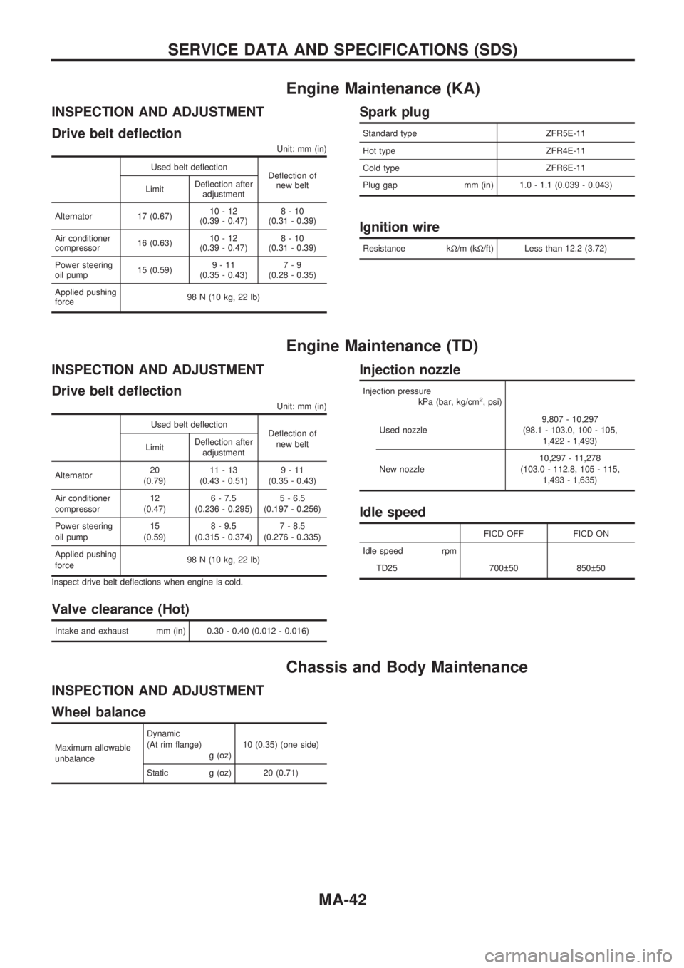
Engine Maintenance (KA)
INSPECTION AND ADJUSTMENT
Drive belt deflection
Unit: mm (in)
Used belt deflection
Deflection of
new belt
LimitDeflection after
adjustment
Alternator 17 (0.67)10-12
(0.39 - 0.47)8-10
(0.31 - 0.39)
Air conditioner
compressor16 (0.63)10-12
(0.39 - 0.47)8-10
(0.31 - 0.39)
Power steering
oil pump15 (0.59)9-11
(0.35 - 0.43)7-9
(0.28 - 0.35)
Applied pushing
force98 N (10 kg, 22 lb)
Spark plug
Standard type ZFR5E-11
Hot type ZFR4E-11
Cold type ZFR6E-11
Plug gap mm (in) 1.0 - 1.1 (0.039 - 0.043)
Ignition wire
Resistance kW/m (kW/ft) Less than 12.2 (3.72)
Engine Maintenance (TD)
INSPECTION AND ADJUSTMENT
Drive belt deflection
Unit: mm (in)
Used belt deflection
Deflection of
new belt
LimitDeflection after
adjustment
Alternator20
(0.79)11-13
(0.43 - 0.51)9-11
(0.35 - 0.43)
Air conditioner
compressor12
(0.47)6 - 7.5
(0.236 - 0.295)5 - 6.5
(0.197 - 0.256)
Power steering
oil pump15
(0.59)8 - 9.5
(0.315 - 0.374)7 - 8.5
(0.276 - 0.335)
Applied pushing
force98 N (10 kg, 22 lb)
Inspect drive belt deflections when engine is cold.
Valve clearance (Hot)
Intake and exhaust mm (in) 0.30 - 0.40 (0.012 - 0.016)
Injection nozzle
Injection pressure
kPa (bar, kg/cm2, psi)
Used nozzle9,807 - 10,297
(98.1 - 103.0, 100 - 105,
1,422 - 1,493)
New nozzle10,297 - 11,278
(103.0 - 112.8, 105 - 115,
1,493 - 1,635)
Idle speed
FICD OFF FICD ON
Idle speed rpm
TD25 700 50 850 50
Chassis and Body Maintenance
INSPECTION AND ADJUSTMENT
Wheel balance
Maximum allowable
unbalanceDynamic
(At rim flange)
g (oz)10 (0.35) (one side)
Static g (oz) 20 (0.71)
SERVICE DATA AND SPECIFICATIONS (SDS)
MA-42
Page 1026 of 1659
Replacing Rear Oil Seal Ð 2WD Model
REMOVAL
1. Remove the propeller shaft. Refer to PD section (``Removal
and Installation'', ``PROPELLER SHAFT'').
2. Remove rear oil seal using Tool.
lAlways replace with a new seal once it has been
removed.
INSTALLATION
1. Install new oil seal until it stops.
lApply multi-purpose grease to seal lip of oil seal before
installing.
2. Install any part removed.
Position Switch Check
lCheck continuity.
Switch Gear position Continuity
Back-up lamp switchReverse Yes
Except reverse No
Neutral position switch
(KA24E engine model
only)Neutral Yes
Except neutral No
SMT476AA
SMT477AA
SMT451BD
ON-VEHICLE SERVICEFS5W71C
MT-9
Page 1028 of 1659

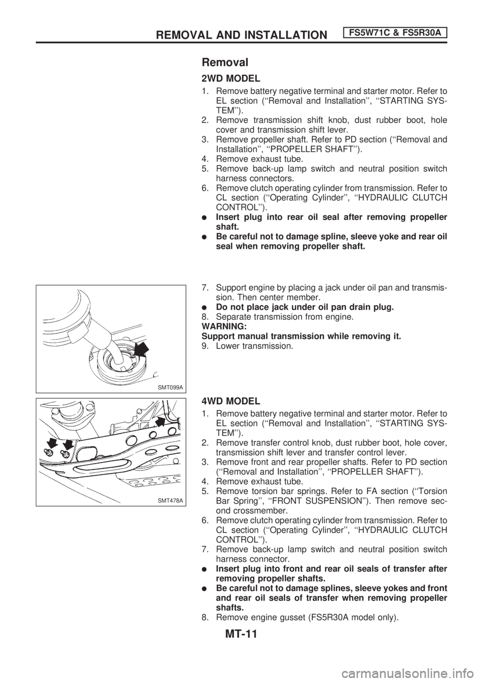
Removal
2WD MODEL
1. Remove battery negative terminal and starter motor. Refer to
EL section (``Removal and Installation'', ``STARTING SYS-
TEM'').
2. Remove transmission shift knob, dust rubber boot, hole
cover and transmission shift lever.
3. Remove propeller shaft. Refer to PD section (``Removal and
Installation'', ``PROPELLER SHAFT'').
4. Remove exhaust tube.
5. Remove back-up lamp switch and neutral position switch
harness connectors.
6. Remove clutch operating cylinder from transmission. Refer to
CL section (``Operating Cylinder'', ``HYDRAULIC CLUTCH
CONTROL'').
lInsert plug into rear oil seal after removing propeller
shaft.
lBe careful not to damage spline, sleeve yoke and rear oil
seal when removing propeller shaft.
7. Support engine by placing a jack under oil pan and transmis-
sion. Then center member.
lDo not place jack under oil pan drain plug.
8. Separate transmission from engine.
WARNING:
Support manual transmission while removing it.
9. Lower transmission.
4WD MODEL
1. Remove battery negative terminal and starter motor. Refer to
EL section (``Removal and Installation'', ``STARTING SYS-
TEM'').
2. Remove transfer control knob, dust rubber boot, hole cover,
transmission shift lever and transfer control lever.
3. Remove front and rear propeller shafts. Refer to PD section
(``Removal and Installation'', ``PROPELLER SHAFT'').
4. Remove exhaust tube.
5. Remove torsion bar springs. Refer to FA section (``Torsion
Bar Spring'', ``FRONT SUSPENSION''). Then remove sec-
ond crossmember.
6. Remove clutch operating cylinder from transmission. Refer to
CL section (``Operating Cylinder'', ``HYDRAULIC CLUTCH
CONTROL'').
7. Remove back-up lamp switch and neutral position switch
harness connector.
lInsert plug into front and rear oil seals of transfer after
removing propeller shafts.
lBe careful not to damage splines, sleeve yokes and front
and rear oil seals of transfer when removing propeller
shafts.
8. Remove engine gusset (FS5R30A model only).
SMT099A
SMT478A
REMOVAL AND INSTALLATIONFS5W71C & FS5R30A
MT-11
Page 1029 of 1659
9. Support transfer and remove center member.
10. Support transmission and remove engine rear member.
11. Separate transmission and transfer from engine.
12. Lower transmission and transfer.
Installation
lApply sealant to areas shown below: Ð 4WD model
SMT782CB
REMOVAL AND INSTALLATIONFS5W71C & FS5R30A
Removal (Cont'd)
MT-12
Page 1030 of 1659
lTighten bolt securing transmission.
lKA24E engine model
Bolt No. Tightening torque Nzm (kg-m, ft-lb)!mm (in)
V139 - 49 (4.0 - 5.0, 29 - 36) 65 (2.56)
V239 - 49 (4.0 - 5.0, 29 - 36) 58 (2.28)
V3* 16 - 22 (1.6 - 2.2, 12 - 16) 25 (0.98)
V416 - 22 (1.6 - 2.2, 12 - 16) 16 (0.63)
*: With nut
lTD25 engine model
Bolt No. Tightening torque Nzm (kg-m, ft-lb)!mm (in)
V139 - 49 (4.0 - 5.0, 29 - 36) 58 (2.28)
V218 - 22 (1.8 - 2.2, 13 - 16) 16 (0.63)
lTighten bolts with T/M bracket, crossmember and frame.
Unit: Nzm (kg-m, ft-lb)
Bolt No. 2WD & 4WD Note
V159-69
(6.0 - 7.0, 43 - 51)Crossmember to frame
V241-52
(4.2 - 5.3, 30 - 38)T/M bracket to crossmember
V368-87
(6.9 - 8.9, 50 - 64)T/M to T/M bracket
SMT305CA
SMT204DA
SMT192D
REMOVAL AND INSTALLATIONFS5W71C & FS5R30A
Installation (Cont'd)
MT-13
Page 1032 of 1659
Gear Components Ð 2WD Model
SMT603D
.
(TD25 engine model)
.
(TD25 engine model)
MAJOR OVERHAULFS5W71C
MT-15
Page 1041 of 1659
lMeasure baulk ring wear.
a. Measure clearance between baulk ring and gear.
Clearance between baulk ring and gear:
Refer to SDS, MT-59.
lIf the clearance is less than the wear limit, replace baulk ring.
lMeasure 2nd & 3rd baulk rings wearÐTD25 engine model
only.
a. Place baulk rings in position on synchronizer cone.
b. While holding baulk rings against synchronizer cone as far as
possible, measure dimensions ``A'' and ``B''.
Standard:
Inner ``A'': 0.7 - 0.9 mm (0.028 - 0.035 in)
Outer ``B'': 0.6 - 1.1 mm (0.024 - 0.043 in)
Wear limit:
0.2 mm (0.008 in)
lIf dimension ``A'' or ``B'' is smaller than the wear limit,
replace outer baulk ring, inner baulk ring and synchro-
nizer cone as a set.
BEARINGS
lMake sure all bearings roll freely and are free from noise,
cracks, pitting or wear.
SMT140
SMT041B
SMT042B
SMT418A
INSPECTIONFS5W71C
Gear Components (Cont'd)
MT-24
Page 1043 of 1659
3. Install main drive gear ball bearing.
a. Press main drive gear ball bearing.
b. Select proper main drive gear bearing snap ring to minimize
clearance of groove.
Allowable clearance of groove:
0 - 0.13 mm (0 - 0.0051 in)
Main drive gear bearing snap ring:
Refer to SDS, MT-59.
c. Install selected snap ring on main drive gear.
4. Assemble synchronizers.
l1st & 2nd synchronizer
l(3rd & 4th synchronizer for TD25 engine model)
l3rd & 4th synchronizer
lOD & Reverse synchronizer
SMT169D
SMT170D
SMT478CB
SMT171D
SMT174DA
ASSEMBLYFS5W71C
Gear Components (Cont'd)
MT-26