1998 NISSAN PICK-UP engine oil
[x] Cancel search: engine oilPage 177 of 1659
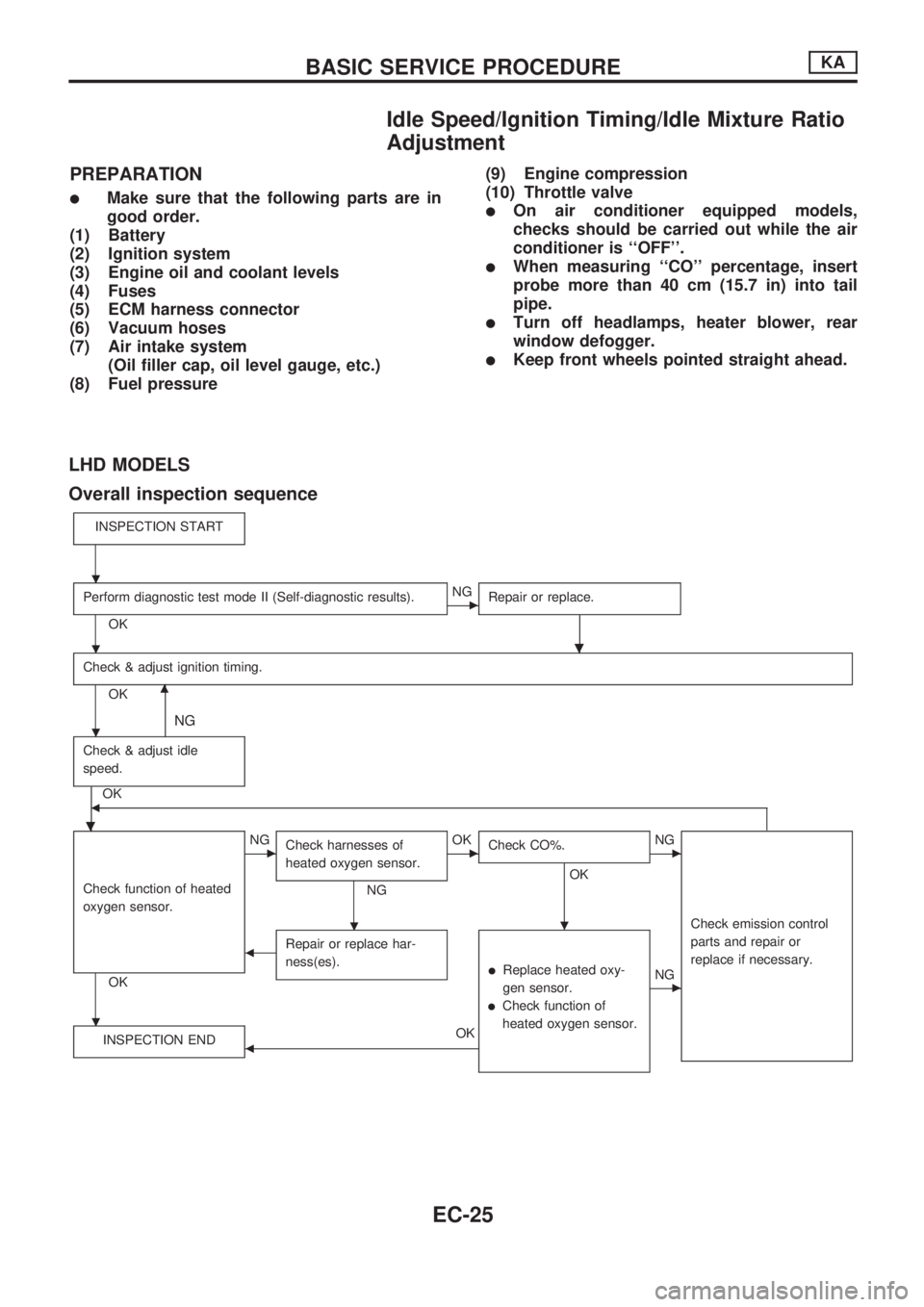
Idle Speed/Ignition Timing/Idle Mixture Ratio
Adjustment
PREPARATION
lMake sure that the following parts are in
good order.
(1) Battery
(2) Ignition system
(3) Engine oil and coolant levels
(4) Fuses
(5) ECM harness connector
(6) Vacuum hoses
(7) Air intake system
(Oil filler cap, oil level gauge, etc.)
(8) Fuel pressure(9) Engine compression
(10) Throttle valvelOn air conditioner equipped models,
checks should be carried out while the air
conditioner is ``OFF''.
lWhen measuring ``CO'' percentage, insert
probe more than 40 cm (15.7 in) into tail
pipe.
lTurn off headlamps, heater blower, rear
window defogger.
lKeep front wheels pointed straight ahead.
LHD MODELS
Overall inspection sequence
INSPECTION START
Perform diagnostic test mode II (Self-diagnostic results).
OK
cNG
Repair or replace.
.
Check & adjust ignition timing.
OKm
NG
Check & adjust idle
speed.
.
OKb
Check function of heated
oxygen sensor.
OK
cNG
Check harnesses of
heated oxygen sensor.
NG
cOK
Check CO%.
OK
.
cNG
Check emission control
parts and repair or
replace if necessary.
bRepair or replace har-
ness(es).
lReplace heated oxy-
gen sensor.
lCheck function of
heated oxygen sensor.
cNG
INSPECTION END
bOK
.
.
.
.
.
BASIC SERVICE PROCEDUREKA
EC-25
Page 199 of 1659
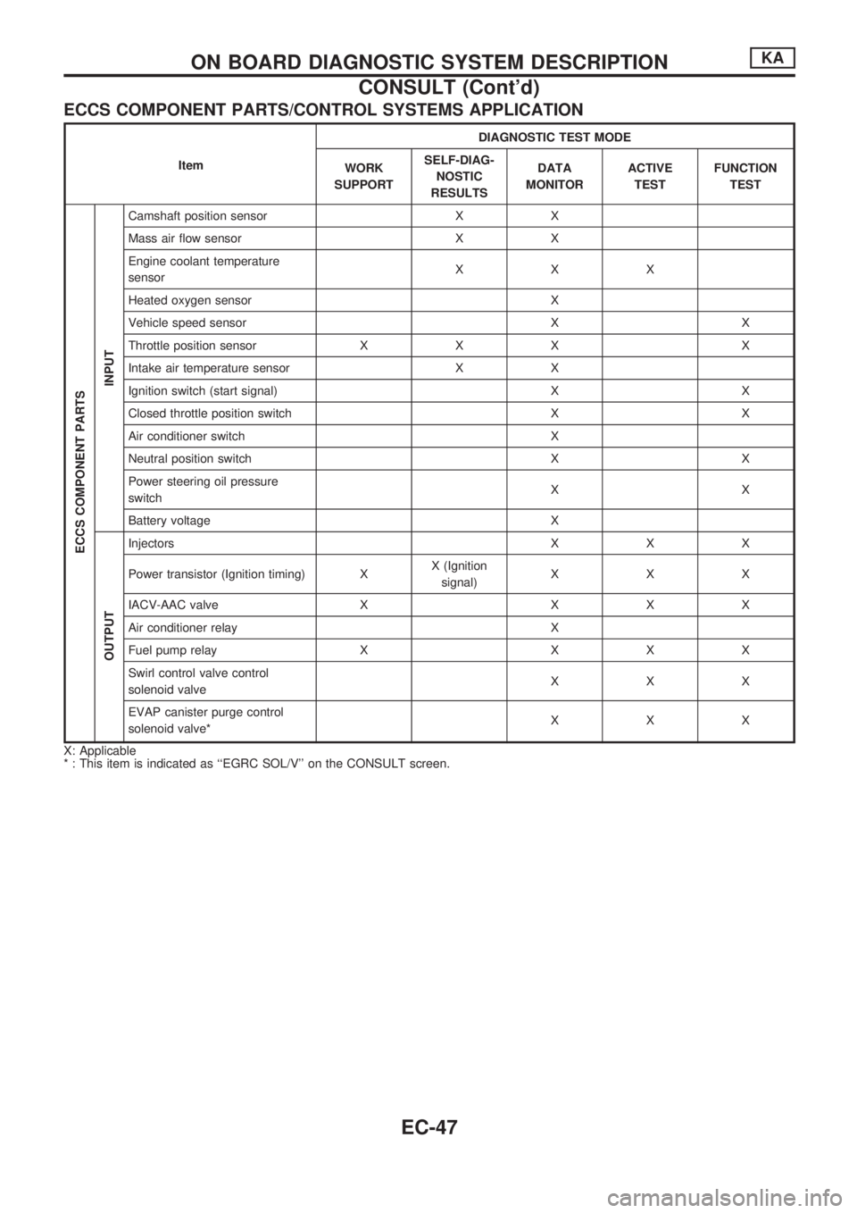
ECCS COMPONENT PARTS/CONTROL SYSTEMS APPLICATION
ItemDIAGNOSTIC TEST MODE
WORK
SUPPORTSELF-DIAG-
NOSTIC
RESULTSDATA
MONITORACTIVE
TESTFUNCTION
TEST
ECCS COMPONENT PARTS
INPUT
Camshaft position sensor X X
Mass air flow sensor X X
Engine coolant temperature
sensorXXX
Heated oxygen sensor X
Vehicle speed sensor X X
Throttle position sensor X X X X
Intake air temperature sensor X X
Ignition switch (start signal) X X
Closed throttle position switch X X
Air conditioner switch X
Neutral position switch X X
Power steering oil pressure
switchXX
Battery voltage X
OUTPUT
Injectors X X X
Power transistor (Ignition timing) XX (Ignition
signal)XXX
IACV-AAC valve X X X X
Air conditioner relay X
Fuel pump relay X X X X
Swirl control valve control
solenoid valveXXX
EVAP canister purge control
solenoid valve*XXX
X: Applicable
* : This item is indicated as ``EGRC SOL/V'' on the CONSULT screen.
ON BOARD DIAGNOSTIC SYSTEM DESCRIPTIONKA
CONSULT (Cont'd)
EC-47
Page 200 of 1659
![NISSAN PICK-UP 1998 Repair Manual SELF-DIAGNOSTIC MODE
Regarding items detected in ``SELF-DIAG RESULTS mode, refer to ``DIAGNOSTIC TROUBLE CODE
INDEX, EC-1.
DATA MONITOR MODE
Monitored item
[Unit]ECM
input
signalsMain
signalsDescr](/manual-img/5/57374/w960_57374-199.png "NISSAN PICK-UP 1998 Repair Manual SELF-DIAGNOSTIC MODE
Regarding items detected in ``SELF-DIAG RESULTS mode, refer to ``DIAGNOSTIC TROUBLE CODE
INDEX, EC-1.
DATA MONITOR MODE
Monitored item
[Unit]ECM
input
signalsMain
signalsDescr")
SELF-DIAGNOSTIC MODE
Regarding items detected in ``SELF-DIAG RESULTS'' mode, refer to ``DIAGNOSTIC TROUBLE CODE
INDEX'', EC-1.
DATA MONITOR MODE
Monitored item
[Unit]ECM
input
signalsMain
signalsDescription Remarks
CMPSRPM
(POS) [rpm]
jj
lIndicates the engine speed computed
from the POS signal (1É signal) of the
camshaft position sensor.
MAS AIR/FL SE [V]
jjlThe signal voltage of the mass air flow
sensor is displayed.lWhen the engine is stopped, a certain
value is indicated.
COOLAN TEMP/S
[ÉC] or [ÉF]
jj
lThe engine coolant temperature (deter-
mined by the signal voltage of the engine
coolant temperature sensor) is displayed.lWhen the engine coolant temperature
sensor is open or short-circuited, ECM
enters fail-safe mode. The engine coolant
temperature determined by the ECM is
displayed.
O2 SEN [V]
jjlThe signal voltage of the heated oxygen
sensor is displayed.lLHD models only
M/R F/C MNT
[RICH/LEAN]
jj
lDisplay of heated oxygen sensor signal
during air-fuel ratio feedback control:
RICH ... means the mixture became
``rich'', and control is being affected
toward a leaner mixture.
LEAN ... means the mixture became
``lean'', and control is being affected
toward a rich mixture.lAfter turning ON the ignition switch,
``RICH'' is displayed until air-fuel mixture
ratio feedback control begins.
lWhen the air-fuel ratio feedback is
clamped, the value just before the clamp-
ing is displayed continuously.
lLHD models only
VHCL SPEED SE
[km/h] or [mph]
jjlThe vehicle speed computed from the
vehicle speed sensor signal is displayed.
BATTERY VOLT [V]
jjlThe power supply voltage of ECM is dis-
played.
THRTL POS SEN [V]
jjlThe throttle position sensor signal volt-
age is displayed.
INT/A TEMP SE
[ÉC] or [ÉF]
j
lThe intake air temperature (determined
by the signal voltage of the intake air
temperature sensor) is indicated.
START SIGNAL
[ON/OFF]
jjlIndicates [ON/OFF] condition from the
starter signal.lAfter starting the engine, [OFF] is
displayed regardless of the starter signal.
CLSD THL/POSI
[ON/OFF]
jj
lIndicates [ON/OFF] condition from the
throttle position sensor signal.
AIR COND SIG
[ON/OFF]
jj
lIndicates [ON/OFF] condition of the air
conditioner switch as determined by the
air conditioner signal.
P/N POSI SW
[ON/OFF]
jj
lIndicates [ON/OFF] condition from the
park/neutral position switch signal.
PW/ST SIGNAL
[ON/OFF]
jj
l[ON/OFF] condition of the power steering
oil pressure switch determined by the
power steering oil pressure signal is indi-
cated.
NOTE:
Any monitored item that does not match the vehicle being diagnosed is deleted from the display automatically.
ON BOARD DIAGNOSTIC SYSTEM DESCRIPTIONKA
CONSULT (Cont'd)
EC-48
Page 202 of 1659
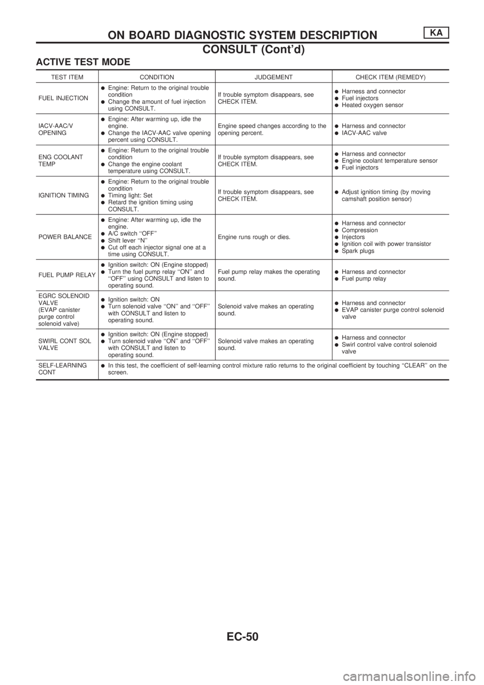
ACTIVE TEST MODE
TEST ITEM CONDITION JUDGEMENT CHECK ITEM (REMEDY)
FUEL INJECTION
lEngine: Return to the original trouble
condition
lChange the amount of fuel injection
using CONSULT.If trouble symptom disappears, see
CHECK ITEM.
lHarness and connectorlFuel injectorslHeated oxygen sensor
IACV-AAC/V
OPENING
lEngine: After warming up, idle the
engine.
lChange the IACV-AAC valve opening
percent using CONSULT.Engine speed changes according to the
opening percent.lHarness and connectorlIACV-AAC valve
ENG COOLANT
TEMP
lEngine: Return to the original trouble
condition
lChange the engine coolant
temperature using CONSULT.If trouble symptom disappears, see
CHECK ITEM.
lHarness and connectorlEngine coolant temperature sensorlFuel injectors
IGNITION TIMING
lEngine: Return to the original trouble
condition
lTiming light: SetlRetard the ignition timing using
CONSULT.If trouble symptom disappears, see
CHECK ITEM.
lAdjust ignition timing (by moving
camshaft position sensor)
POWER BALANCE
lEngine: After warming up, idle the
engine.
lA/C switch ``OFF''lShift lever ``N''lCut off each injector signal one at a
time using CONSULT.Engine runs rough or dies.
lHarness and connectorlCompressionlInjectorslIgnition coil with power transistorlSpark plugs
FUEL PUMP RELAY
lIgnition switch: ON (Engine stopped)lTurn the fuel pump relay ``ON'' and
``OFF'' using CONSULT and listen to
operating sound.Fuel pump relay makes the operating
sound.lHarness and connectorlFuel pump relay
EGRC SOLENOID
VALVE
(EVAP canister
purge control
solenoid valve)
lIgnition switch: ONlTurn solenoid valve ``ON'' and ``OFF''
with CONSULT and listen to
operating sound.Solenoid valve makes an operating
sound.lHarness and connectorlEVAP canister purge control solenoid
valve
SWIRL CONT SOL
VALVE
lIgnition switch: ON (Engine stopped)lTurn solenoid valve ``ON'' and ``OFF''
with CONSULT and listen to
operating sound.Solenoid valve makes an operating
sound.lHarness and connectorlSwirl control valve control solenoid
valve
SELF-LEARNING
CONT
lIn this test, the coefficient of self-learning control mixture ratio returns to the original coefficient by touching ``CLEAR'' on the
screen.
ON BOARD DIAGNOSTIC SYSTEM DESCRIPTIONKA
CONSULT (Cont'd)
EC-50
Page 204 of 1659
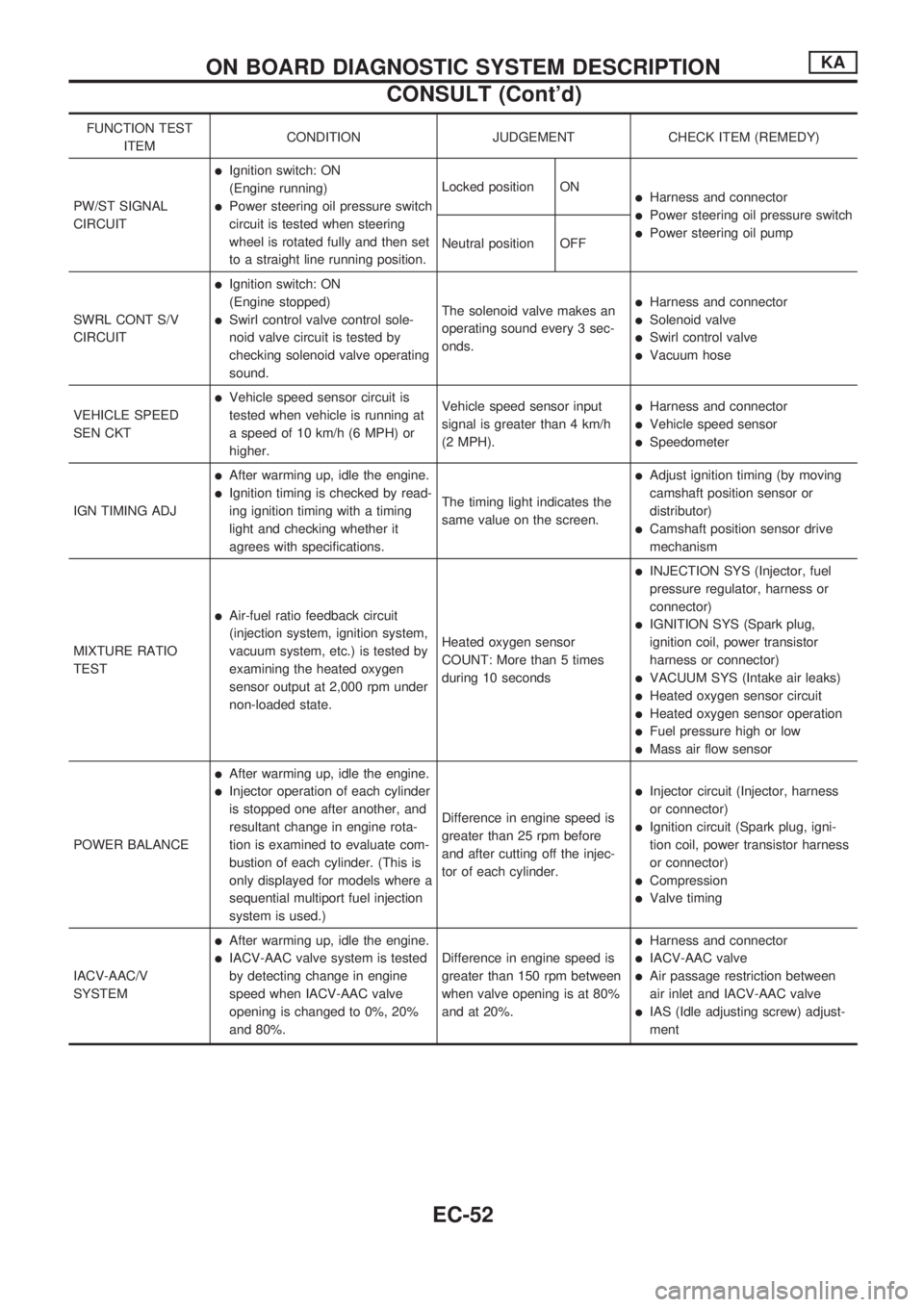
FUNCTION TEST
ITEMCONDITION JUDGEMENT CHECK ITEM (REMEDY)
PW/ST SIGNAL
CIRCUIT
lIgnition switch: ON
(Engine running)
lPower steering oil pressure switch
circuit is tested when steering
wheel is rotated fully and then set
to a straight line running position.Locked position ONlHarness and connector
lPower steering oil pressure switch
lPower steering oil pump
Neutral position OFF
SWRL CONT S/V
CIRCUIT
lIgnition switch: ON
(Engine stopped)
lSwirl control valve control sole-
noid valve circuit is tested by
checking solenoid valve operating
sound.The solenoid valve makes an
operating sound every 3 sec-
onds.
lHarness and connector
lSolenoid valve
lSwirl control valve
lVacuum hose
VEHICLE SPEED
SEN CKT
lVehicle speed sensor circuit is
tested when vehicle is running at
a speed of 10 km/h (6 MPH) or
higher.Vehicle speed sensor input
signal is greater than 4 km/h
(2 MPH).lHarness and connector
lVehicle speed sensor
lSpeedometer
IGN TIMING ADJ
lAfter warming up, idle the engine.
lIgnition timing is checked by read-
ing ignition timing with a timing
light and checking whether it
agrees with specifications.The timing light indicates the
same value on the screen.
lAdjust ignition timing (by moving
camshaft position sensor or
distributor)
lCamshaft position sensor drive
mechanism
MIXTURE RATIO
TEST
lAir-fuel ratio feedback circuit
(injection system, ignition system,
vacuum system, etc.) is tested by
examining the heated oxygen
sensor output at 2,000 rpm under
non-loaded state.Heated oxygen sensor
COUNT: More than 5 times
during 10 seconds
lINJECTION SYS (Injector, fuel
pressure regulator, harness or
connector)
lIGNITION SYS (Spark plug,
ignition coil, power transistor
harness or connector)
lVACUUM SYS (Intake air leaks)
lHeated oxygen sensor circuit
lHeated oxygen sensor operation
lFuel pressure high or low
lMass air flow sensor
POWER BALANCE
lAfter warming up, idle the engine.
lInjector operation of each cylinder
is stopped one after another, and
resultant change in engine rota-
tion is examined to evaluate com-
bustion of each cylinder. (This is
only displayed for models where a
sequential multiport fuel injection
system is used.)Difference in engine speed is
greater than 25 rpm before
and after cutting off the injec-
tor of each cylinder.lInjector circuit (Injector, harness
or connector)
lIgnition circuit (Spark plug, igni-
tion coil, power transistor harness
or connector)
lCompression
lValve timing
IACV-AAC/V
SYSTEM
lAfter warming up, idle the engine.
lIACV-AAC valve system is tested
by detecting change in engine
speed when IACV-AAC valve
opening is changed to 0%, 20%
and 80%.Difference in engine speed is
greater than 150 rpm between
when valve opening is at 80%
and at 20%.
lHarness and connector
lIACV-AAC valve
lAir passage restriction between
air inlet and IACV-AAC valve
lIAS (Idle adjusting screw) adjust-
ment
ON BOARD DIAGNOSTIC SYSTEM DESCRIPTIONKA
CONSULT (Cont'd)
EC-52
Page 214 of 1659

Symptom Matrix Chart
SYMPTOM
Reference page
HARD/NO START/RESTART (EXCP. HA)
ENGINE STALL
HESITATION/SURGING/FLAT SPOT
SPARK KNOCK/DETONATION
LACK OF POWER/POOR ACCELERATION
HIGH IDLE/LOW IDLE
ROUGH IDLE/HUNTING
IDLING VIBRATION
SLOW/NO RETURN TO IDLE
OVERHEATS/WATER TEMPERATURE HIGH
EXCESSIVE FUEL CONSUMPTION
EXCESSIVE OIL CONSUMPTION
BATTERY DEAD (UNDER CHARGE)
OVERCOOLS
OVERCHARGING
Warranty Symptom Code AA AB AC AD AE AF AG AH AJ AK AL AM HA 1P 1X
Basic engine control system
Fuel Fuel pump circuitllljlljjjEC-151
Fuel pressure regulator system
llljljlljlEC-22
Injector circuit
llljlll lEC-144
Evaporative emission systemjjjj
ljjjj jEC-19
Air Positive crankcase ventilation systemjjjj
ljjjj jjEC-21
Incorrect idle speed adjustmentjj jjjj jEC-25
Swirl control valve circuitjj
lEC-161
IACV-AAC valve circuit
llljllllljjEC-131
IACV-FICD solenoid valve circuitjjjjjjjjj jEC-168
Ignition Incorrect ignition timing adjustmentjj
lll ll lEC-25
Ignition circuit
lllll ll lEC-99
EVAP EVAP canister purge control solenoid
valve circuit
ljjjj j jEC-140
Main power supply and ground circuit
llljj jj jj jEC-75
Air conditioner circuitjjjjjjjjj j jHA section
ECCS system
ECCS Camshaft position sensor circuitllllljj jEC-82
Mass air flow sensor circuit
lllll ljjEC-89
Heated oxygen sensor circuit
lljlljlEC-123, 127
Engine coolant temperature sensor circuit
llljllljjlEC-95
Throttle position sensor circuit
ll lllll lEC-113
Incorrect throttle position sensor adjust-
ment
ljjljjljEC-58
Vehicle speed sensor circuitjj j jEC-118
ECMjjjjjjjjjjjEC-61
Start signal circuitjEC-149
Neutral position switch circuitjjjj jEC-136
Power steering oil pressure switch circuitjjjEC-157
l; High Possibility Item
j; Low Possibility Item(continued on next page)
TROUBLE DIAGNOSIS Ð General DescriptionKA
EC-62
Page 215 of 1659
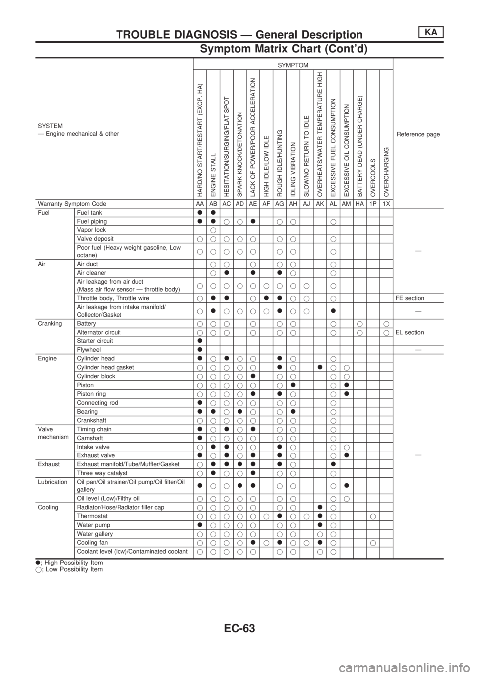
SYSTEM
Ð Engine mechanical & otherSYMPTOM
Reference page
HARD/NO START/RESTART (EXCP. HA)
ENGINE STALL
HESITATION/SURGING/FLAT SPOT
SPARK KNOCK/DETONATION
LACK OF POWER/POOR ACCELERATION
HIGH IDLE/LOW IDLE
ROUGH IDLE/HUNTING
IDLING VIBRATION
SLOW/NO RETURN TO IDLE
OVERHEATS/WATER TEMPERATURE HIGH
EXCESSIVE FUEL CONSUMPTION
EXCESSIVE OIL CONSUMPTION
BATTERY DEAD (UNDER CHARGE)
OVERCOOLS
OVERCHARGING
Warranty Symptom Code AA AB AC AD AE AF AG AH AJ AK AL AM HA 1P 1X
Fuel Fuel tank
ll
Ð Fuel piping
lljjljj j
Vapor lockj
Valve depositjjjjj jj j
Poor fuel (Heavy weight gasoline, Low
octane)jjjjj jj j
Air Air ductjjjjj j
Air cleanerj
llljj
Air leakage from air duct
(Mass air flow sensor Ð throttle body)jjjjjjjjj j
Throttle body, Throttle wirej
lljlljj jFE section
Air leakage from intake manifold/
Collector/Gasketj
ljjjjljjlÐ
Cranking Batteryjjjjjj jjj
EL section Alternator circuitjjjjjj jjj
Starter circuit
l
FlywheellÐ
Engine Cylinder head
ljljjljj
Ð Cylinder head gasketjjjjj
ljljj
Cylinder blockjjjj
ljj jj
Pistonjjjjj j
ljl
Piston ringjjjjlljjl
Connecting rodljjjj jj j
Bearing
lljljjlj
Crankshaftjjjjj jj j
Valve
mechanismTiming chain
ljljljj j
Camshaft
ljjjj jj j
Intake valvej
lljjljjj
Exhaust valve
ljljlljjl
Exhaust Exhaust manifold/Tube/Muffler/Gasketjllll ljl
Three way catalystjljjljj j
Lubrication Oil pan/Oil strainer/Oil pump/Oil filter/Oil
gallery
ljjlljj jl
Oil level (Low)/Filthy oiljjjjj jj jj
Cooling Radiator/Hose/Radiator filler capjjjjj jj
lj
Thermostatjjjjjj
ljjljj
Water pump
ljjjj jjlj
Water galleryjjjjj jj jj
Cooling fanjjjj
ljljjljj
Coolant level (low)/Contaminated coolantjjjjj jj jj
l; High Possibility Item
j; Low Possibility Item
TROUBLE DIAGNOSIS Ð General DescriptionKA
Symptom Matrix Chart (Cont'd)
EC-63
Page 224 of 1659
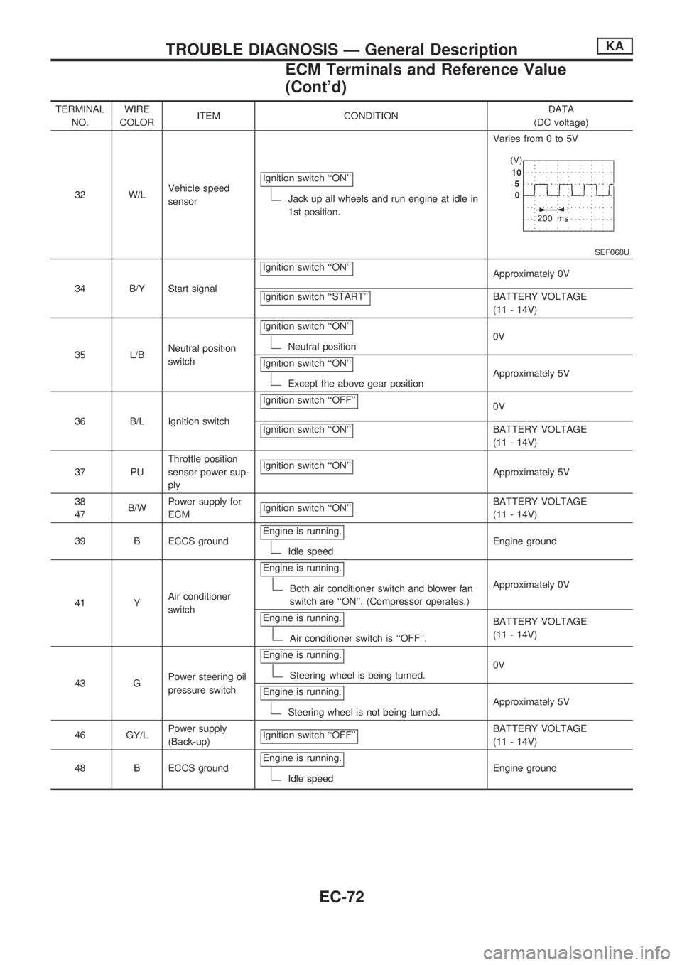
TERMINAL
NO.WIRE
COLORITEM CONDITIONDATA
(DC voltage)
32 W/LVehicle speed
sensorIgnition switch ``ON''
Jack up all wheels and run engine at idle in
1st position.Varies from 0 to 5V
SEF068U
34 B/Y Start signalIgnition switch ``ON''
Approximately 0V
Ignition switch ``START''
BATTERY VOLTAGE
(11 - 14V)
35 L/BNeutral position
switchIgnition switch ``ON''
Neutral position0V
Ignition switch ``ON''
Except the above gear positionApproximately 5V
36 B/L Ignition switchIgnition switch ``OFF''
0V
Ignition switch ``ON''
BATTERY VOLTAGE
(11 - 14V)
37 PUThrottle position
sensor power sup-
plyIgnition switch ``ON''
Approximately 5V
38
47B/WPower supply for
ECMIgnition switch ``ON''
BATTERY VOLTAGE
(11 - 14V)
39 B ECCS groundEngine is running.
Idle speedEngine ground
41 YAir conditioner
switchEngine is running.
Both air conditioner switch and blower fan
switch are ``ON''. (Compressor operates.)Approximately 0V
Engine is running.
Air conditioner switch is ``OFF''.BATTERY VOLTAGE
(11 - 14V)
43 GPower steering oil
pressure switchEngine is running.
Steering wheel is being turned.0V
Engine is running.
Steering wheel is not being turned.Approximately 5V
46 GY/LPower supply
(Back-up)Ignition switch ``OFF''
BATTERY VOLTAGE
(11 - 14V)
48 B ECCS groundEngine is running.
Idle speedEngine ground
TROUBLE DIAGNOSIS Ð General DescriptionKA
ECM Terminals and Reference Value
(Cont'd)
EC-72