1998 NISSAN PICK-UP engine oil
[x] Cancel search: engine oilPage 439 of 1659
Bulb Replacement
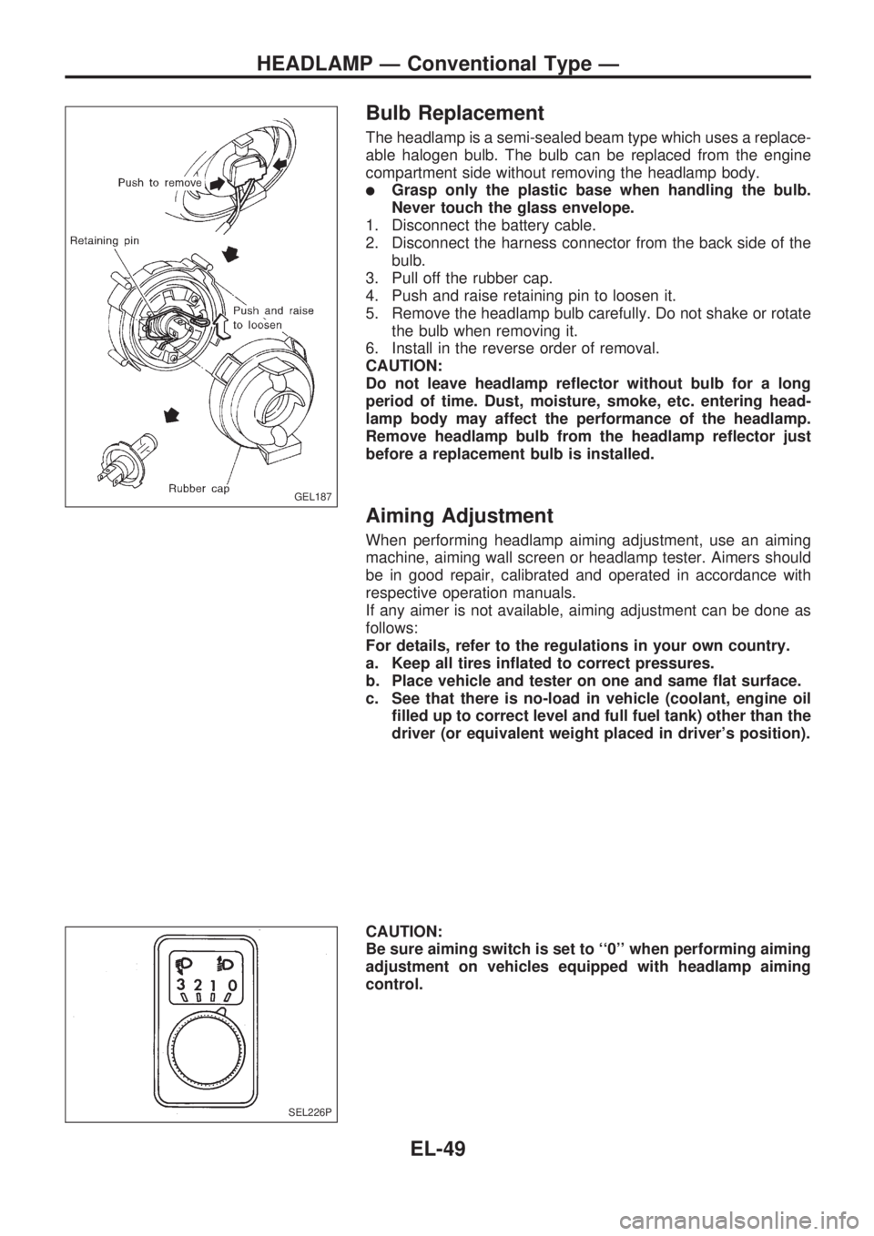
The headlamp is a semi-sealed beam type which uses a replace-
able halogen bulb. The bulb can be replaced from the engine
compartment side without removing the headlamp body.
lGrasp only the plastic base when handling the bulb.
Never touch the glass envelope.
1. Disconnect the battery cable.
2. Disconnect the harness connector from the back side of the
bulb.
3. Pull off the rubber cap.
4. Push and raise retaining pin to loosen it.
5. Remove the headlamp bulb carefully. Do not shake or rotate
the bulb when removing it.
6. Install in the reverse order of removal.
CAUTION:
Do not leave headlamp reflector without bulb for a long
period of time. Dust, moisture, smoke, etc. entering head-
lamp body may affect the performance of the headlamp.
Remove headlamp bulb from the headlamp reflector just
before a replacement bulb is installed.
Aiming Adjustment
When performing headlamp aiming adjustment, use an aiming
machine, aiming wall screen or headlamp tester. Aimers should
be in good repair, calibrated and operated in accordance with
respective operation manuals.
If any aimer is not available, aiming adjustment can be done as
follows:
For details, refer to the regulations in your own country.
a. Keep all tires inflated to correct pressures.
b. Place vehicle and tester on one and same flat surface.
c. See that there is no-load in vehicle (coolant, engine oil
filled up to correct level and full fuel tank) other than the
driver (or equivalent weight placed in driver's position).
CAUTION:
Be sure aiming switch is set to ``0'' when performing aiming
adjustment on vehicles equipped with headlamp aiming
control.
GEL187
SEL226P
HEADLAMP Ð Conventional Type Ð
EL-49
Page 506 of 1659
Electrical Components Inspection
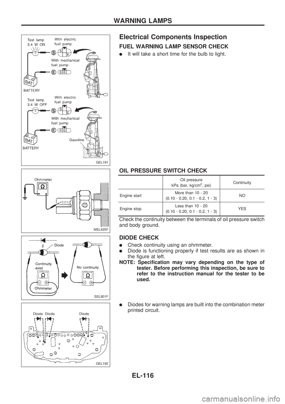
FUEL WARNING LAMP SENSOR CHECK
lIt will take a short time for the bulb to light.
OIL PRESSURE SWITCH CHECK
Oil pressure
kPa (bar, kg/cm2, psi)Continuity
Engine startMore than 10 - 20
(0.10 - 0.20, 0.1 - 0.2,1-3)NO
Engine stopLess than 10 - 20
(0.10 - 0.20, 0.1 - 0.2,1-3)YES
Check the continuity between the terminals of oil pressure switch
and body ground.
DIODE CHECK
lCheck continuity using an ohmmeter.
lDiode is functioning properly if test results are as shown in
the figure at left.
NOTE: Specification may vary depending on the type of
tester. Before performing this inspection, be sure to
refer to the instruction manual for the tester to be
used.
lDiodes for warning lamps are built into the combination meter
printed circuit.
GEL191
MEL425F
SEL901F
GEL192
WARNING LAMPS
EL-116
Page 532 of 1659
Trouble Diagnoses
Symptom Possible causes Repair order
Radio inoperative (no digital
display and no sound from
speakers).1. 10A fuse
2. Poor radio case ground
3. Radio1. Check 10A fuse (No.
18, located in fuse block). Turn igni-
tion switch ON and verify battery positive voltage is present
at terminal
V10of radio.
2. Check radio case ground.
3. Remove radio for repair.
Radio controls are operational,
but no sound is heard from
any speaker.1. Radio output
2. Radio1. Check radio output voltages.
2. Remove radio for repair.
Radio presets are lost when
ignition switch is turned OFF.1. 7.5A fuse
2. Radio1. Check 7.5A fuse (No.
6, located in fuse block) and verify
battery positive voltage is present at terminal
V6of radio.
2. Remove radio for repair.
Individual speaker is noisy or
inoperative.1. Speaker
2. Radio output
3. Speaker circuit
4. Radio1. Check speaker.
2. Check radio output voltages.
3. Check wires for open or short between radio and speaker.
4. Remove radio for repair.
Radio stations are weak or
noisy.1. Antenna
2. Poor radio ground
3. Radio1. Check antenna.
2. Check radio ground.
3. Remove radio for repair.
Radio generates static noise
with engine running.1. Poor radio ground
2. Loose or missing ground bonding straps
3. Ignition condenser or rear window defogger
noise suppressor condenser
4. Alternator
5. Ignition coil or secondary wiring
6. Radio1. Check radio ground.
2. Check ground bonding straps.
3. Replace ignition condenser or rear window defogger noise
suppressor condenser.
4. Check alternator.
5. Check ignition coil and secondary wiring.
6. Remove radio for repair.
Radio generates static noise
with accessories on (switch
pops and motor noise).1. Poor radio ground
2. Antenna
3. Accessory ground
4. Faulty accessory1. Check radio ground.
2. Check antenna.
3. Check accessory ground.
4. Replace accessory.
SPEAKER INSPECTION
1. Disconnect speaker harness connector.
2. Measure the resistance between speaker terminals
V1andV2.
lThe resistance should be2-4W.
3. Using jumper wires, momentarily connect a 9V battery between speaker terminals
V1andV2.
lA momentary hum or pop should be heard.
ANTENNA INSPECTION
Using a jumper wire, clip an auxiliary ground between antenna and body.
lIf reception improves, check antenna ground (at body surface).
lIf reception does not improve, check main feeder cable for short circuit or open circuit.
RADIO INSPECTION
All voltage inspections are made with:
lIgnition switch ON or ACC
lRadio ON
lRadio connected (If removed for inspection, supply a ground to the case using a jumper wire.)
AUDIO
EL-142
Page 643 of 1659
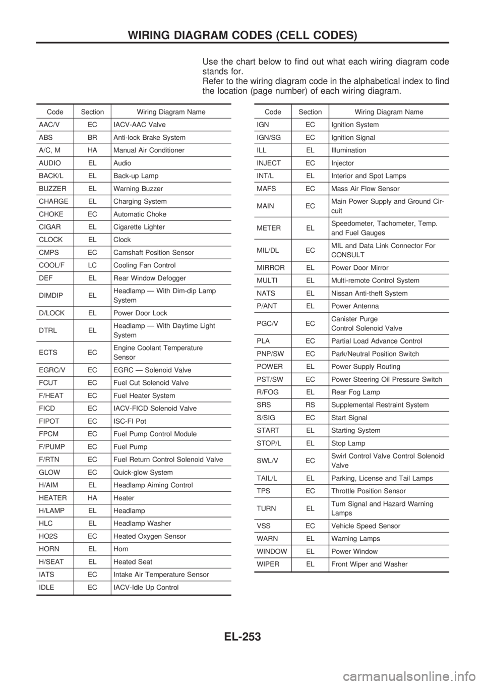
Use the chart below to find out what each wiring diagram code
stands for.
Refer to the wiring diagram code in the alphabetical index to find
the location (page number) of each wiring diagram.
Code Section Wiring Diagram Name
AAC/V EC IACV-AAC Valve
ABS BR Anti-lock Brake System
A/C, M HA Manual Air Conditioner
AUDIO EL Audio
BACK/L EL Back-up Lamp
BUZZER EL Warning Buzzer
CHARGE EL Charging System
CHOKE EC Automatic Choke
CIGAR EL Cigarette Lighter
CLOCK EL Clock
CMPS EC Camshaft Position Sensor
COOL/F LC Cooling Fan Control
DEF EL Rear Window Defogger
DIMDIP ELHeadlamp Ð With Dim-dip Lamp
System
D/LOCK EL Power Door Lock
DTRL ELHeadlamp Ð With Daytime Light
System
ECTS ECEngine Coolant Temperature
Sensor
EGRC/V EC EGRC Ð Solenoid Valve
FCUT EC Fuel Cut Solenoid Valve
F/HEAT EC Fuel Heater System
FICD EC IACV-FICD Solenoid Valve
FIPOT EC ISC-FI Pot
FPCM EC Fuel Pump Control Module
F/PUMP EC Fuel Pump
F/RTN EC Fuel Return Control Solenoid Valve
GLOW EC Quick-glow System
H/AIM EL Headlamp Aiming Control
HEATER HA Heater
H/LAMP EL Headlamp
HLC EL Headlamp Washer
HO2S EC Heated Oxygen Sensor
HORN EL Horn
H/SEAT EL Heated Seat
IATS EC Intake Air Temperature Sensor
IDLE EC IACV-Idle Up ControlCode Section Wiring Diagram Name
IGN EC Ignition System
IGN/SG EC Ignition Signal
ILL EL Illumination
INJECT EC Injector
INT/L EL Interior and Spot Lamps
MAFS EC Mass Air Flow Sensor
MAIN ECMain Power Supply and Ground Cir-
cuit
METER ELSpeedometer, Tachometer, Temp.
and Fuel Gauges
MIL/DL ECMIL and Data Link Connector For
CONSULT
MIRROR EL Power Door Mirror
MULTI EL Multi-remote Control System
NATS EL Nissan Anti-theft System
P/ANT EL Power Antenna
PGC/V ECCanister Purge
Control Solenoid Valve
PLA EC Partial Load Advance Control
PNP/SW EC Park/Neutral Position Switch
POWER EL Power Supply Routing
PST/SW EC Power Steering Oil Pressure Switch
R/FOG EL Rear Fog Lamp
SRS RS Supplemental Restraint System
S/SIG EC Start Signal
START EL Starting System
STOP/L EL Stop Lamp
SWL/V ECSwirl Control Valve Control Solenoid
Valve
TAIL/L EL Parking, License and Tail Lamps
TPS EC Throttle Position Sensor
TURN ELTurn Signal and Hazard Warning
Lamps
VSS EC Vehicle Speed Sensor
WARN EL Warning Lamps
WINDOW EL Power Window
WIPER EL Front Wiper and Washer
WIRING DIAGRAM CODES (CELL CODES)
EL-253
Page 644 of 1659
ENGINE MECHANICAL
SECTION
EM
CONTENTS
PRECAUTIONS......................................................... 1
Parts Requiring Angular Tightening....................... 1
Liquid Gasket Application Procedure .................... 1
PREPARATION......................................................... 2
Special Service Tools ............................................ 2
Commercial Service Tools ..................................... 7
KA
OUTER COMPONENT PARTS................................. 9
COMPRESSION PRESSURE.................................. 10
Measurement of Compression Pressure ............. 10
OIL PAN................................................................... 11
Removal ............................................................... 11
Installation ............................................................ 12
TIMING CHAIN........................................................ 13
Removal ............................................................... 13
Inspection ............................................................. 17
Installation ............................................................ 17
OIL SEAL REPLACEMENT.................................... 22
Valve Oil Seal ...................................................... 22
Front Oil Seal ....................................................... 22
Rear Oil Seal ....................................................... 23
CYLINDER HEAD.................................................... 24
Removal ............................................................... 25
Disassembly ......................................................... 27
Inspection ............................................................. 27
Assembly.............................................................. 33
Installation ............................................................ 34
ENGINE REMOVAL................................................. 36
Removal ............................................................... 37
Installation ............................................................ 37
CYLINDER BLOCK................................................. 38Disassembly ......................................................... 39
Inspection ............................................................. 39
Assembly.............................................................. 45
TD
OUTER COMPONENT PARTS............................... 49
COMPRESSION PRESSURE.................................. 51
Measurement of Compression Pressure ............. 51
OIL PAN................................................................... 52
Removal ............................................................... 52
Installation ............................................................ 52
CYLINDER HEAD.................................................... 53
Removal ............................................................... 54
Disassembly ......................................................... 55
Inspection ............................................................. 56
Assembly.............................................................. 62
Installation ............................................................ 63
OIL SEAL REPLACEMENT.................................... 67
ENGINE REMOVAL................................................. 69
Removal ............................................................... 70
Installation ............................................................ 70
ENGINE OVERHAUL.............................................. 71
Disassembly ......................................................... 72
Inspection and Replacement ............................... 74
Assembly.............................................................. 86
KA
SERVICE DATA AND SPECIFICATIONS (SDS)... 91
General Specifications ......................................... 91
Inspection and Adjustment .................................. 91
EM
Page 646 of 1659
Parts Requiring Angular Tightening
lUse an angle wrench for the final tightening of the following
engine parts:
(1) Cylinder head bolts
(2) Connecting rod cap nuts for gasoline engines
lDo not use a torque value for final tightening.
lThe torque value for these parts are for a preliminary step.
lEnsure thread and seat surfaces are clean and coated with
engine oil.
Liquid Gasket Application Procedure
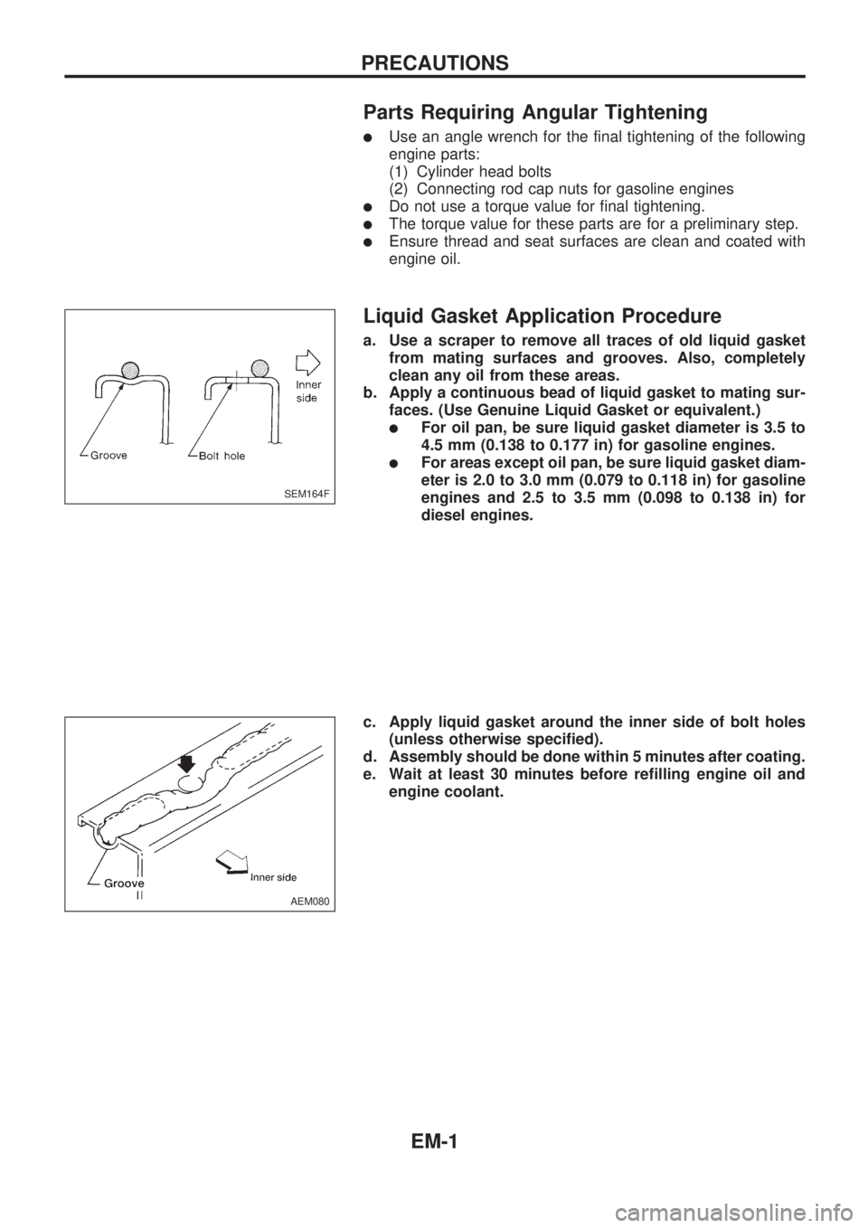
a. Use a scraper to remove all traces of old liquid gasket
from mating surfaces and grooves. Also, completely
clean any oil from these areas.
b. Apply a continuous bead of liquid gasket to mating sur-
faces. (Use Genuine Liquid Gasket or equivalent.)
lFor oil pan, be sure liquid gasket diameter is 3.5 to
4.5 mm (0.138 to 0.177 in) for gasoline engines.
lFor areas except oil pan, be sure liquid gasket diam-
eter is 2.0 to 3.0 mm (0.079 to 0.118 in) for gasoline
engines and 2.5 to 3.5 mm (0.098 to 0.138 in) for
diesel engines.
c. Apply liquid gasket around the inner side of bolt holes
(unless otherwise specified).
d. Assembly should be done within 5 minutes after coating.
e. Wait at least 30 minutes before refilling engine oil and
engine coolant.
SEM164F
AEM080
PRECAUTIONS
EM-1
Page 648 of 1659
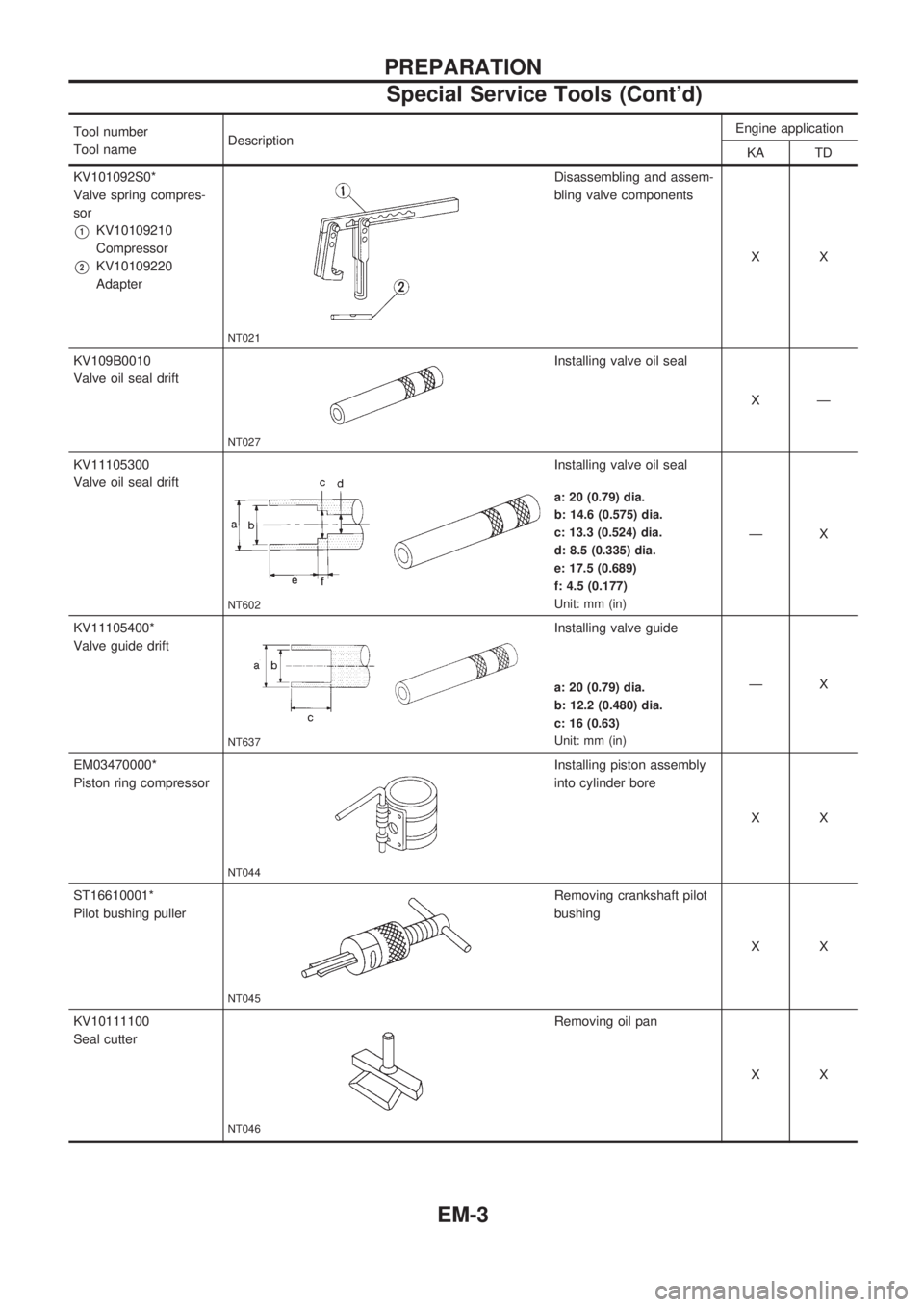
Tool number
Tool nameDescriptionEngine application
KA TD
KV101092S0*
Valve spring compres-
sor
V1KV10109210
Compressor
V2KV10109220
Adapter
NT021
Disassembling and assem-
bling valve components
XX
KV109B0010
Valve oil seal drift
NT027
Installing valve oil seal
XÐ
KV11105300
Valve oil seal drift
NT602
Installing valve oil seal
ÐX
a: 20 (0.79) dia.
b: 14.6 (0.575) dia.
c: 13.3 (0.524) dia.
d: 8.5 (0.335) dia.
e: 17.5 (0.689)
f: 4.5 (0.177)
Unit: mm (in)
KV11105400*
Valve guide drift
NT637
Installing valve guide
ÐX
a: 20 (0.79) dia.
b: 12.2 (0.480) dia.
c: 16 (0.63)
Unit: mm (in)
EM03470000*
Piston ring compressor
NT044
Installing piston assembly
into cylinder bore
XX
ST16610001*
Pilot bushing puller
NT045
Removing crankshaft pilot
bushing
XX
KV10111100
Seal cutter
NT046
Removing oil pan
XX
PREPARATION
Special Service Tools (Cont'd)
EM-3
Page 649 of 1659
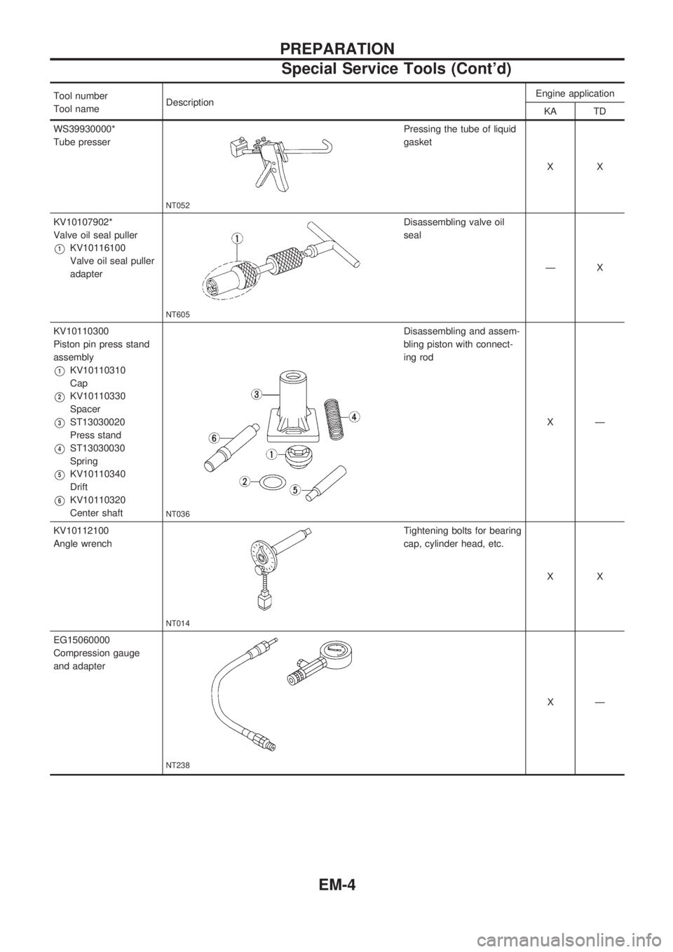
Tool number
Tool nameDescriptionEngine application
KA TD
WS39930000*
Tube presser
NT052
Pressing the tube of liquid
gasket
XX
KV10107902*
Valve oil seal puller
V1KV10116100
Valve oil seal puller
adapter
NT605
Disassembling valve oil
seal
ÐX
KV10110300
Piston pin press stand
assembly
V1KV10110310
Cap
V2KV10110330
Spacer
V3ST13030020
Press stand
V4ST13030030
Spring
V5KV10110340
Drift
V6KV10110320
Center shaft
NT036
Disassembling and assem-
bling piston with connect-
ing rod
XÐ
KV10112100
Angle wrench
NT014
Tightening bolts for bearing
cap, cylinder head, etc.
XX
EG15060000
Compression gauge
and adapter
NT238
XÐ
PREPARATION
Special Service Tools (Cont'd)
EM-4