1998 NISSAN PICK-UP engine oil
[x] Cancel search: engine oilPage 311 of 1659
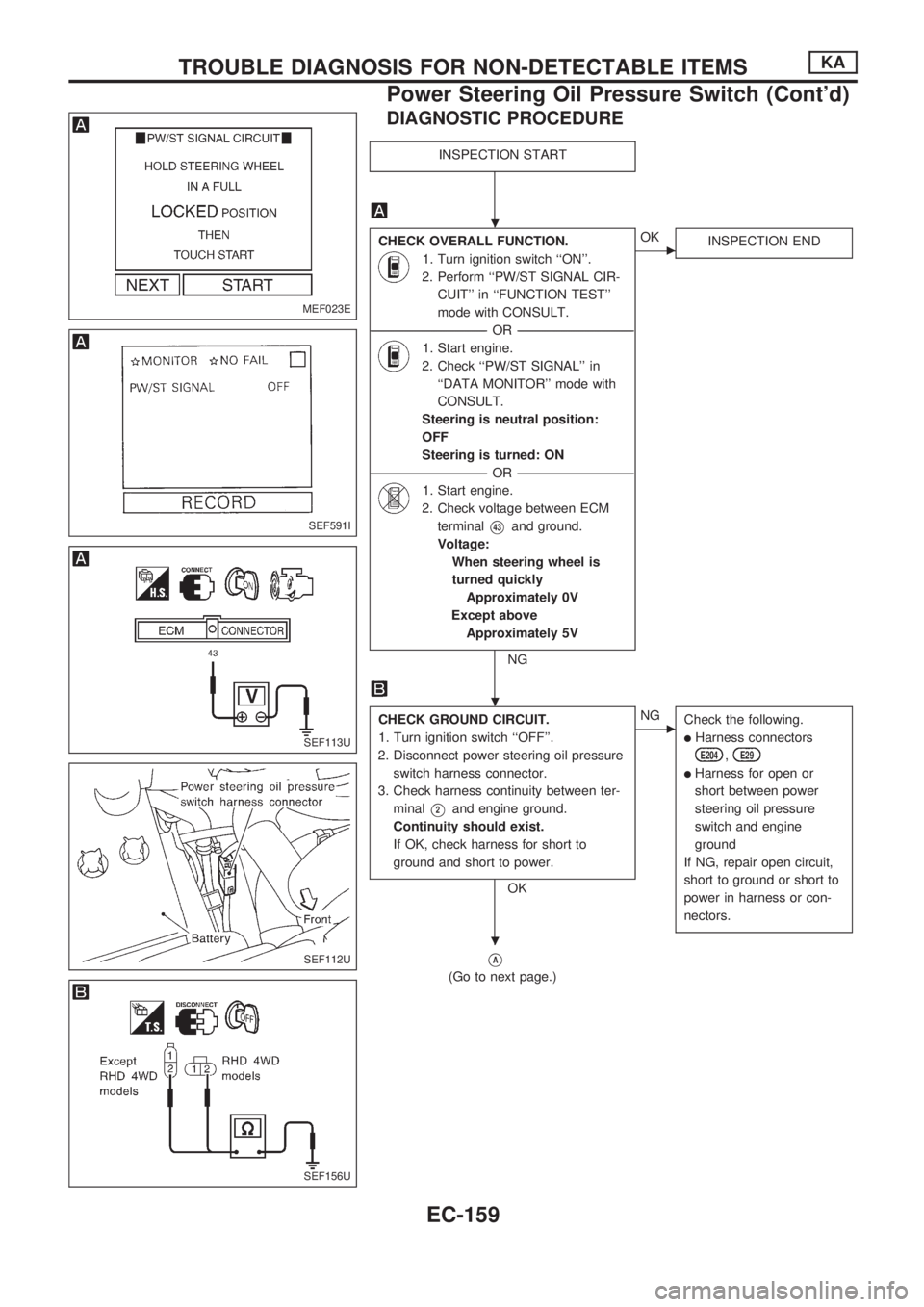
DIAGNOSTIC PROCEDURE
INSPECTION START
CHECK OVERALL FUNCTION.
1. Turn ignition switch ``ON''.
2. Perform ``PW/ST SIGNAL CIR-
CUIT'' in ``FUNCTION TEST''
mode with CONSULT.
----------------------------------------------------------------------------------------------------------------------------------OR----------------------------------------------------------------------------------------------------------------------------------
1. Start engine.
2. Check ``PW/ST SIGNAL'' in
``DATA MONITOR'' mode with
CONSULT.
Steering is neutral position:
OFF
Steering is turned: ON
----------------------------------------------------------------------------------------------------------------------------------OR----------------------------------------------------------------------------------------------------------------------------------
1. Start engine.
2. Check voltage between ECM
terminal
V43and ground.
Voltage:
When steering wheel is
turned quickly
Approximately 0V
Except above
Approximately 5V
NG
cOK
INSPECTION END
CHECK GROUND CIRCUIT.
1. Turn ignition switch ``OFF''.
2. Disconnect power steering oil pressure
switch harness connector.
3. Check harness continuity between ter-
minal
V2and engine ground.
Continuity should exist.
If OK, check harness for short to
ground and short to power.
OK
cNG
Check the following.
lHarness connectors
E204,E29
lHarness for open or
short between power
steering oil pressure
switch and engine
ground
If NG, repair open circuit,
short to ground or short to
power in harness or con-
nectors.
VA
(Go to next page.)
MEF023E
SEF591I
SEF113U
SEF112U
SEF156U
.
.
.
TROUBLE DIAGNOSIS FOR NON-DETECTABLE ITEMSKA
Power Steering Oil Pressure Switch (Cont'd)
EC-159
Page 312 of 1659
VA
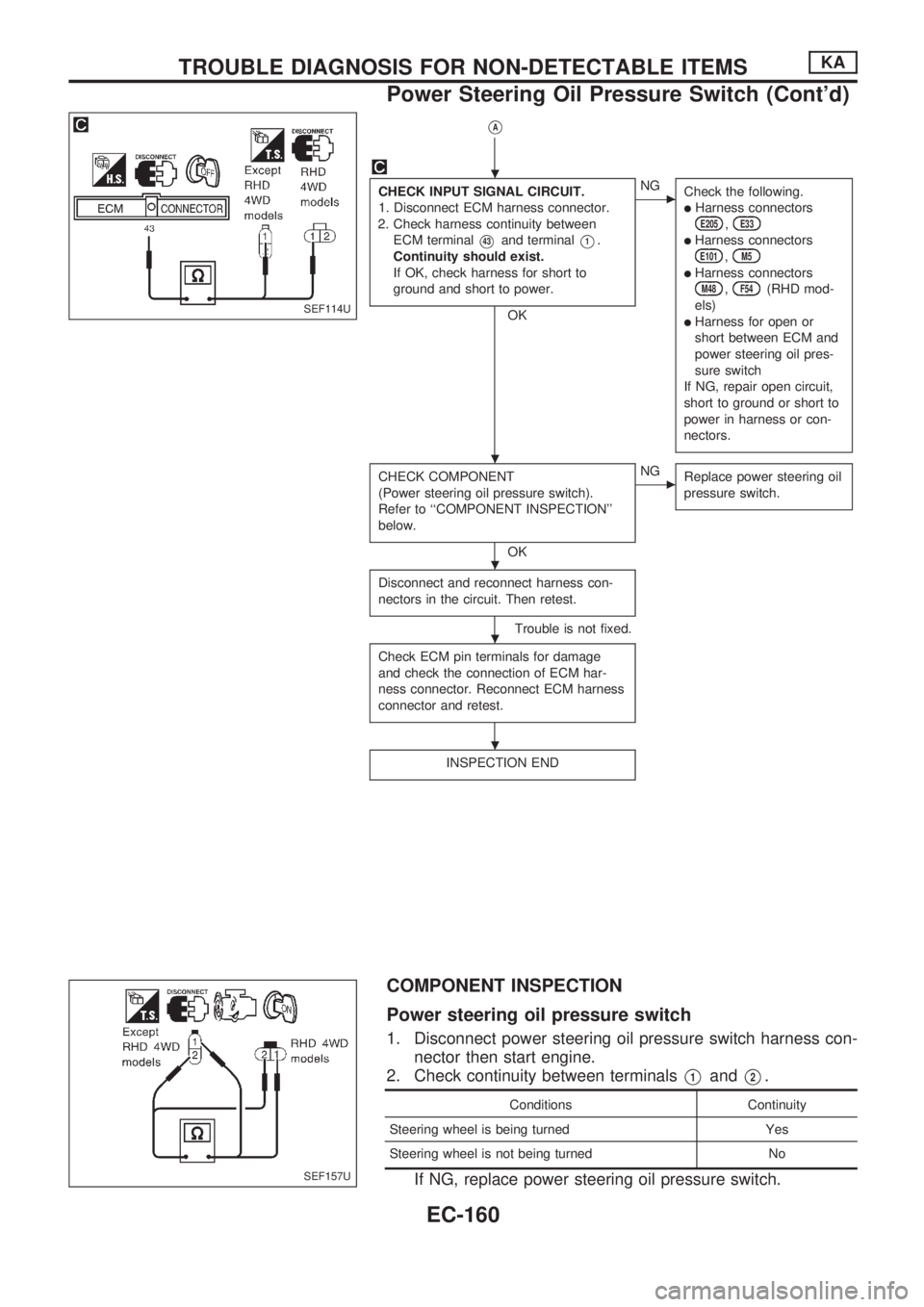
CHECK INPUT SIGNAL CIRCUIT.
1. Disconnect ECM harness connector.
2. Check harness continuity between
ECM terminal
V43and terminalV1.
Continuity should exist.
If OK, check harness for short to
ground and short to power.
OK
cNG
Check the following.
lHarness connectorsE205,E33
lHarness connectorsE101,M5
lHarness connectorsM48,F54(RHD mod-
els)
lHarness for open or
short between ECM and
power steering oil pres-
sure switch
If NG, repair open circuit,
short to ground or short to
power in harness or con-
nectors.
CHECK COMPONENT
(Power steering oil pressure switch).
Refer to ``COMPONENT INSPECTION''
below.
OK
cNG
Replace power steering oil
pressure switch.
Disconnect and reconnect harness con-
nectors in the circuit. Then retest.
Trouble is not fixed.
Check ECM pin terminals for damage
and check the connection of ECM har-
ness connector. Reconnect ECM harness
connector and retest.
INSPECTION END
COMPONENT INSPECTION
Power steering oil pressure switch
1. Disconnect power steering oil pressure switch harness con-
nector then start engine.
2. Check continuity between terminals
V1andV2.
Conditions Continuity
Steering wheel is being turned Yes
Steering wheel is not being turned No
If NG, replace power steering oil pressure switch.
SEF114U
SEF157U
.
.
.
.
.
TROUBLE DIAGNOSIS FOR NON-DETECTABLE ITEMSKA
Power Steering Oil Pressure Switch (Cont'd)
EC-160
Page 333 of 1659
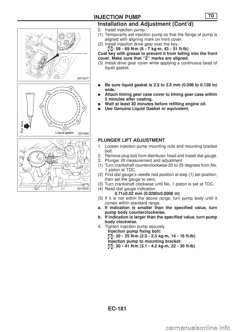
2. Install injection pump.
(1) Temporarily set injection pump so that the flange of pump is
aligned with aligning mark on front cover.
(2) Install injection drive gear over the key.
:59-69Nzm (6 - 7 kg-m, 43 - 51 ft-lb)
Coat key with grease to prevent it from falling into the front
cover. Make sure that ``Z'' marks are aligned.
(3) Install drive gear cover while applying a continuous bead of
liquid gasket.
lBe sure liquid gasket is 2.5 to 3.5 mm (0.098 to 0.138 in)
wide.
lAttach timing gear case cover to timing gear case within
5 minutes after coating.
lWait at least 30 minutes before refilling engine oil.
lUse Genuine Liquid Gasket or equivalent.
PLUNGER LIFT ADJUSTMENT
1. Loosen injection pump mounting nuts and mounting bracket
bolt.
2. Remove plug bolt from distributor head and install dial gauge.
3. Plunger lift measurement and adjustment
(1) Turn crankshaft counterclockwise 20 to 25 degrees from No.
1 piston at TDC.
(2) Find dial gauge's needle rest position at step (1) set position,
then set the gauge to zero.
(3) Turn crankshaft clockwise until No. 1 piston is set at TDC.
(4) Read dial gauge indication.
0.71 0.02 mm (0.0280 0.0008 in)
(5) If it is not within the above range, turn pump body until it
comes within standard range.
a. If indication is smaller than the specified value, turn
pump body counterclockwise.
b. If indication is larger than the specified value, turn pump
body clockwise.
4. Tighten injection pump securely.
Injection pump fixing bolt:
:20-25Nzm (2.0 - 2.5 kg-m, 14 - 18 ft-lb)
Injection pump to mounting bracket:
:30-41Nzm (3.1 - 4.2 kg-m, 22 - 30 ft-lb)
SEF337F
SEF626I
SEF065K
INJECTION PUMPTD
Installation and Adjustment (Cont'd)
EC-181
Page 381 of 1659
When installing, use a new O-ring.
WARNING:
Do not touch the cooled fuel temperature switch with your
bare hand.
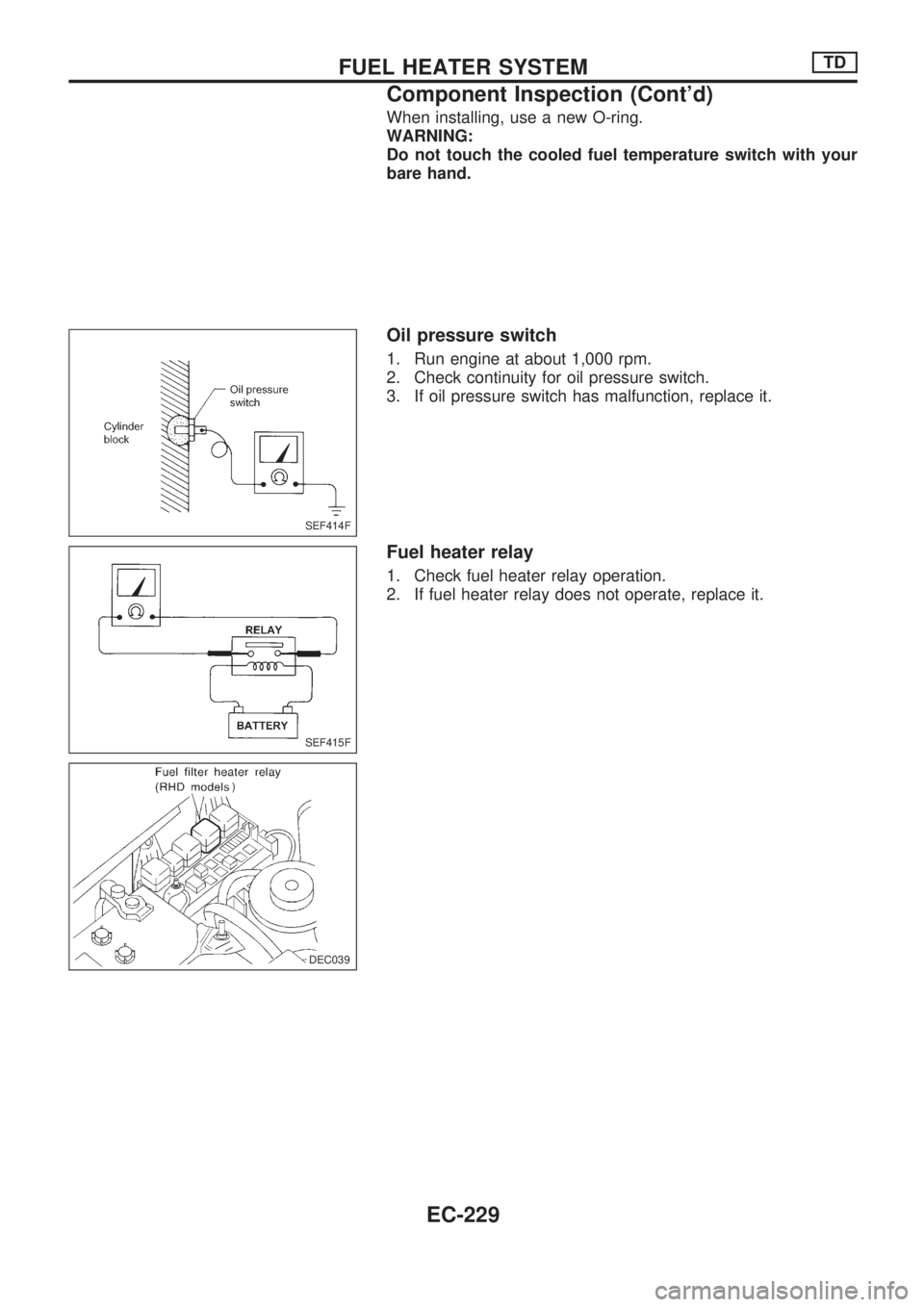
Oil pressure switch
1. Run engine at about 1,000 rpm.
2. Check continuity for oil pressure switch.
3. If oil pressure switch has malfunction, replace it.
Fuel heater relay
1. Check fuel heater relay operation.
2. If fuel heater relay does not operate, replace it.
SEF414F
SEF415F
DEC039
.)
.DEC039
FUEL HEATER SYSTEMTD
Component Inspection (Cont'd)
EC-229
Page 384 of 1659
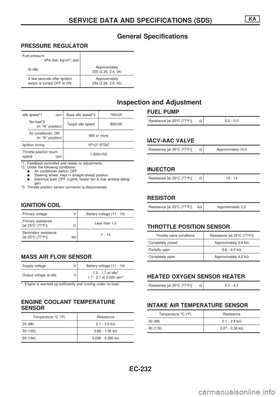
General Specifications
PRESSURE REGULATOR
Fuel pressure
kPa (bar, kg/cm2, psi)
At idleApproximately
235 (2.35, 2.4, 34)
A few seconds after ignition
switch is turned OFF to ONApproximately
294 (2.94, 3.0, 43)
Inspection and Adjustment
Idle speed*1 rpm Base idle speed*3 750 25
No-load*2
(in ``N'' position)Target idle speed 800 50
Air conditioner: ON
(in ``N'' position)900 or more
Ignition timing 10É 2É BTDC
Throttle position touch
speed rpm1,000 150
*1: Feedback controlled and needs no adjustments
*2: Under the following conditions:
lAir conditioner switch: OFFlSteering wheel: Kept in straight-ahead positionlElectrical load: OFF (Lights, heater fan & rear window defog-
ger)
*3: Throttle position sensor connector is disconnected.
IGNITION COIL
Primary voltage V Battery voltage (11 - 14)
Primary resistance
[at 25ÉC (77ÉF)]WLess than 1.0
Secondary resistance
[at 25ÉC (77ÉF)] kW7-13
MASS AIR FLOW SENSOR
Supply voltage V Battery voltage (11 - 14)
Output voltage at idle V1.3 - 1.7 at idle*
1.7 - 2.1 at 2,500 rpm*
*: Engine is warmed up sufficiently and running under no-load.
ENGINE COOLANT TEMPERATURE
SENSOR
Temperature ÉC (ÉF) Resistance
20 (68) 2.1 - 2.9 kW
50 (122) 0.68 - 1.00 kW
90 (194) 0.236 - 0.260 kW
FUEL PUMP
Resistance [at 25ÉC (77ÉF)]W0.2 - 5.0
IACV-AAC VALVE
Resistance [at 25ÉC (77ÉF)]WApproximately 10.0
INJECTOR
Resistance [at 25ÉC (77ÉF)]W10-14
RESISTOR
Resistance [at 25ÉC (77ÉF)] kWApproximately 2.2
THROTTLE POSITION SENSOR
Throttle valve conditions Resistance [at 25ÉC (77ÉF)]
Completely closed Approximately 0.6 kW
Partially open 0.6 - 4.0 kW
Completely open Approximately 4.0 kW
HEATED OXYGEN SENSOR HEATER
Resistance [at 25ÉC (77ÉF)]W2.3 - 4.3
INTAKE AIR TEMPERATURE SENSOR
Temperature ÉC (ÉF) Resistance
20 (68) 2.1 - 2.9 kW
80 (176) 0.27 - 0.38 kW
SERVICE DATA AND SPECIFICATIONS (SDS)KA
EC-232
Page 407 of 1659
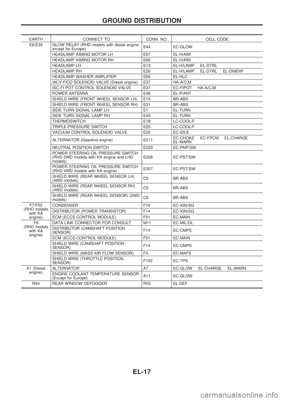
EARTH CONNECT TO CONN. NO. CELL CODE
E6/E39 GLOW RELAY (RHD models with diesel engine
except for Europe)E44 EC-GLOW
HEADLAMP AIMING MOTOR LH E57 EL-H/AIM
HEADLAMP AIMING MOTOR RH E60 EL-H/AIM
HEADLAMP LH E13 EL-H/LAMP EL-DTRL
HEADLAMP RH E26 EL-H/LAMP EL-DTRL EL-DIMDIP
HEADLAMP WASHER AMPLIFIER E65 EL-HLC
IACV-FICD SOLENOID VALVE (Diesel engine) E37 HA-A/C,M
ISC-FI POT CONTROL SOLENOID VALVE E37 EC-FIPOT HA-A/C,M
POWER ANTENNA E46 EL-P/ANT
SHIELD WIRE (FRONT WHEEL SENSOR LH) E15 BR-ABS
SHIELD WIRE (FRONT WHEEL SENSOR RH) E31 BR-ABS
SIDE TURN SIGNAL LAMP LH E1 EL-TURN
SIDE TURN SIGNAL LAMP RH E45 EL-TURN
THERMOSWITCH E18 LC-COOL/F
TRIPLE-PRESSURE SWITCH E25 LC-COOL/F
VACUUM CONTROL SOLENOID VALVE E20 EC-IDLE
ALTERNATOR (Gasoline engine) E211EC-CHOKE EC-FPCM EL-CHARGE
EL-WARN
NEUTRAL POSITION SWITCH E220 EC-PNP/SW
POWER STEERING OIL PRESSURE SWITCH
(RHD 2WD models with KA engine and LHD
models)E208 EC-PST/SW
POWER STEERING OIL PRESSURE SWITCH
(RHD 4WD models with KA engine)E207 EC-PST/SW
SHIELD WIRE (REAR WHEEL SENSOR LH)
(4WD models)C5 BR-ABS
SHIELD WIRE (REAR WHEEL SENSOR RH)
(4WD models)C5 BR-ABS
SHIELD WIRE (REAR WHEEL SENSOR) (2WD
models)C6 BR-ABS
F7/F52
(RHD models
with KA
engine)CONDENSER F10 EC-IGN/SG
DISTRIBUTOR (POWER TRANSISTOR) F14 EC-IGN/SG
ECM (ECCS CONTROL MODULE) F51 EC-MAIN
F8
(RHD models
with KA
engine)DATA LINK CONNECTOR FOR CONSULT M11 EC-MIL/DL
DISTRIBUTOR (CAMSHAFT POSITION
SENSOR)F14 EC-CMPS
ECM (ECCS CONTROL MODULE) F51 EC-MAIN
SHIELD WIRE (CAMSHAFT POSITION
SENSOR)F14 EC-CMPS
SHIELD WIRE (MASS AIR FLOW SENSOR) F4 EC-MAFS
SHIELD WIRE (THROTTLE POSITION
SENSOR)F102 EC-TPS
A1 (Diesel
engine)ALTERNATOR A7 EC-GLOW EL-CHARGE EL-WARN
ENGINE COOLANT TEMPERATURE SENSOR
(Except for Europe)A11 EC-GLOW
R54 REAR WINDOW DEFOGGER R53 EL-DEF
GROUND DISTRIBUTION
EL-17
Page 426 of 1659
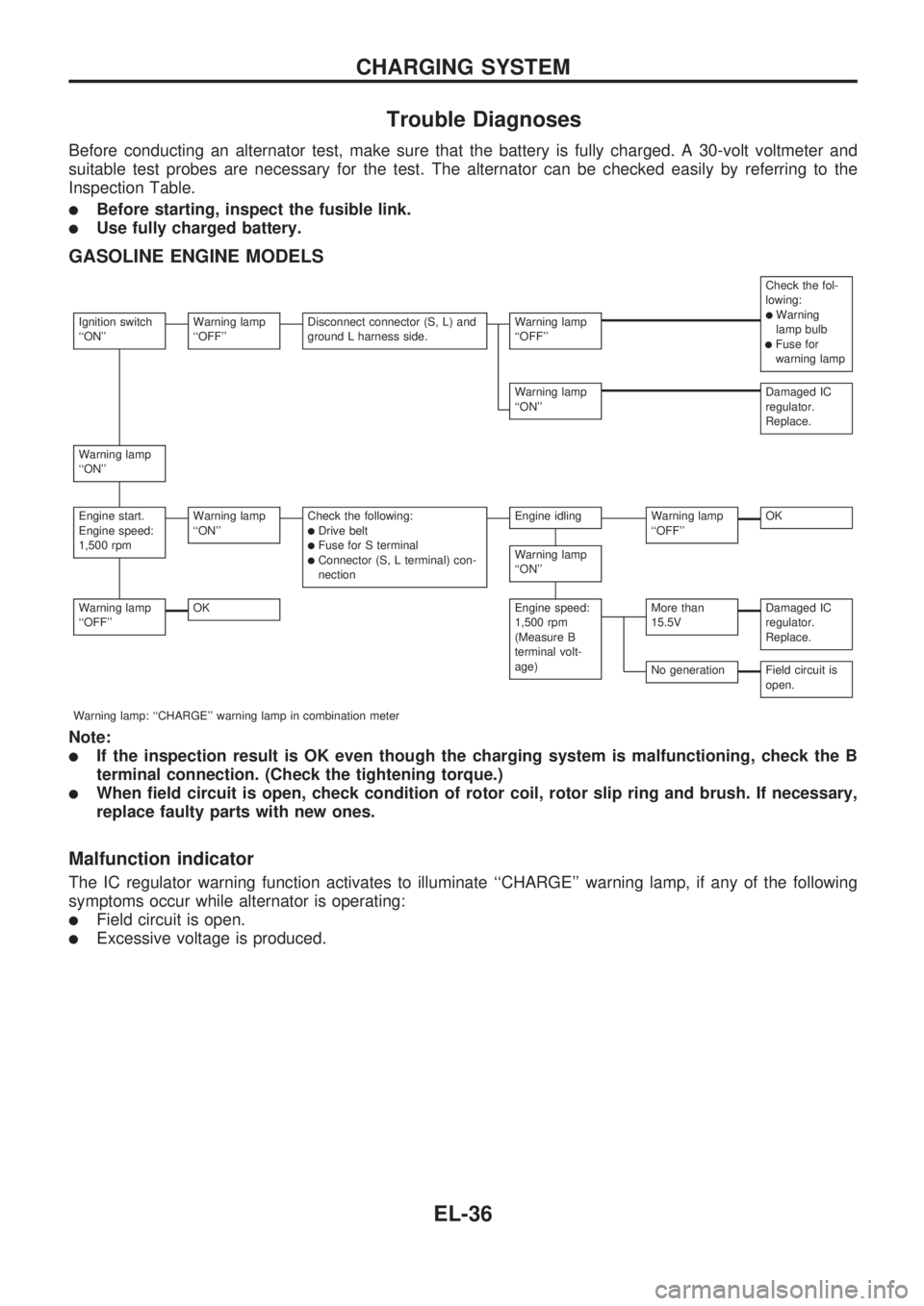
Trouble Diagnoses
Before conducting an alternator test, make sure that the battery is fully charged. A 30-volt voltmeter and
suitable test probes are necessary for the test. The alternator can be checked easily by referring to the
Inspection Table.
lBefore starting, inspect the fusible link.
lUse fully charged battery.
GASOLINE ENGINE MODELS
Check the fol-
lowing:
lWarning
lamp bulb
lFuse for
warning lamp
Ignition switch
``ON''Warning lamp
``OFF''Disconnect connector (S, L) and
ground L harness side.Warning lamp
``OFF''
Warning lamp
``ON''Damaged IC
regulator.
Replace.
Warning lamp
``ON''
Engine start.
Engine speed:
1,500 rpmWarning lamp
``ON''Check the following:lDrive beltlFuse for S terminallConnector (S, L terminal) con-
nection
Engine idlingWarning lamp
``OFF''OK
Warning lamp
``ON''
Warning lamp
``OFF''OKEngine speed:
1,500 rpm
(Measure B
terminal volt-
age)More than
15.5VDamaged IC
regulator.
Replace.
No generationField circuit is
open.
Warning lamp: ``CHARGE'' warning lamp in combination meter
Note:
lIf the inspection result is OK even though the charging system is malfunctioning, check the B
terminal connection. (Check the tightening torque.)
lWhen field circuit is open, check condition of rotor coil, rotor slip ring and brush. If necessary,
replace faulty parts with new ones.
Malfunction indicator
The IC regulator warning function activates to illuminate ``CHARGE'' warning lamp, if any of the following
symptoms occur while alternator is operating:
lField circuit is open.
lExcessive voltage is produced.
CHARGING SYSTEM
EL-36
Page 427 of 1659
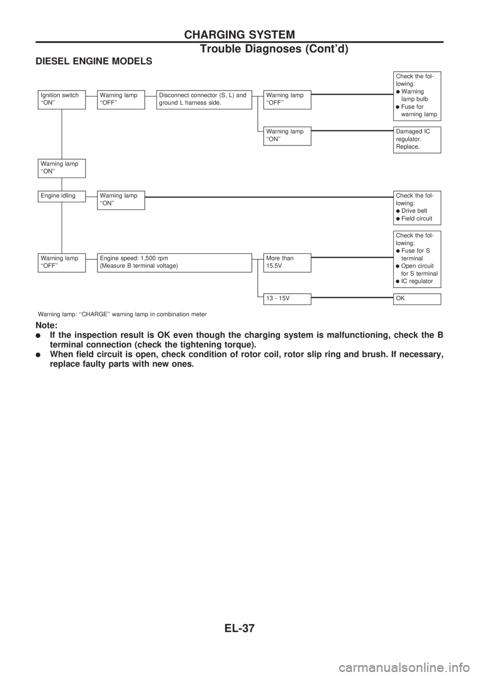
DIESEL ENGINE MODELS
Check the fol-
lowing:
lWarning
lamp bulb
lFuse for
warning lamp
Ignition switch
``ON''Warning lamp
``OFF''Disconnect connector (S, L) and
ground L harness side.Warning lamp
``OFF''
Warning lamp
``ON''Damaged IC
regulator.
Replace.
Warning lamp
``ON''
Engine idlingWarning lamp
``ON''Check the fol-
lowing:
lDrive beltlField circuit
Check the fol-
lowing:
lFuse for S
terminal
lOpen circuit
for S terminal
lIC regulator
Warning lamp
``OFF''Engine speed: 1,500 rpm
(Measure B terminal voltage)More than
15.5V
13 - 15VOK
Warning lamp: ``CHARGE'' warning lamp in combination meter
Note:
lIf the inspection result is OK even though the charging system is malfunctioning, check the B
terminal connection (check the tightening torque).
lWhen field circuit is open, check condition of rotor coil, rotor slip ring and brush. If necessary,
replace faulty parts with new ones.
CHARGING SYSTEM
Trouble Diagnoses (Cont'd)
EL-37