Page 1640 of 1659
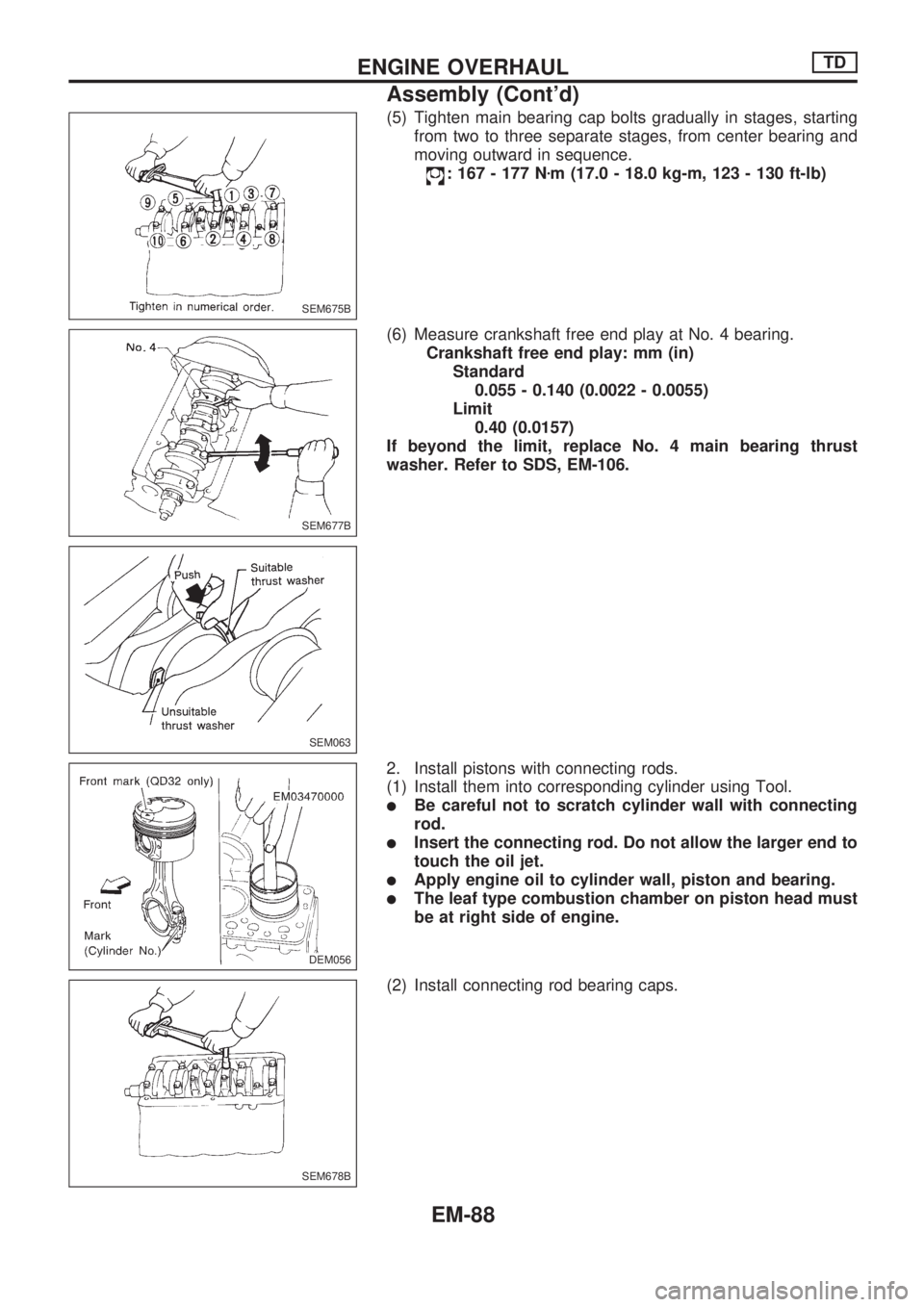
Install piston assembly.
CAUTION:
lStretch the piston rings only enough to fit them in the
piston grooves.
lAlways install new piston rings with the position marks
facing up.
Identification color
Top ring Yellow
2nd ring Red
lInstall No. 1 piston ring in such a way that its gap faces
the direction of the piston pin; and then install piston
rings so that their gap positioned at 180É to one another.
CRANKSHAFT
1. Install crankshaft.
(1) Set main bearings in the proper position on cylinder block.
a. If either crankshaft, cylinder block or main bearing is
reused again, it is necessary to measure main bearing
clearance.
b. Upper bearings have oil hole and oil groove, however
lower bearings do not.
(2) Apply engine oil to crankshaft journal and pin and install
crankshaft.
(3) Install main bearing caps.
a. Install main bearing cap with the number facing the front of
vehicle.
b. Apply engine oil to main bearing cap and cylinder block con-
tact surfaces.
c. Install rear oil seal assembly. Apply engine oil to contact
surface of rear end oil seal and crankshaft.
(4) Install crankshaft thrust washer at the 4th journal from front.
Install thrust washer so that oil groove can face crankshaft.
DEM059
DEM055
SEM674BA
SEM057
ENGINE OVERHAULTD
Assembly (Cont'd)
EM-87
Page 1641 of 1659
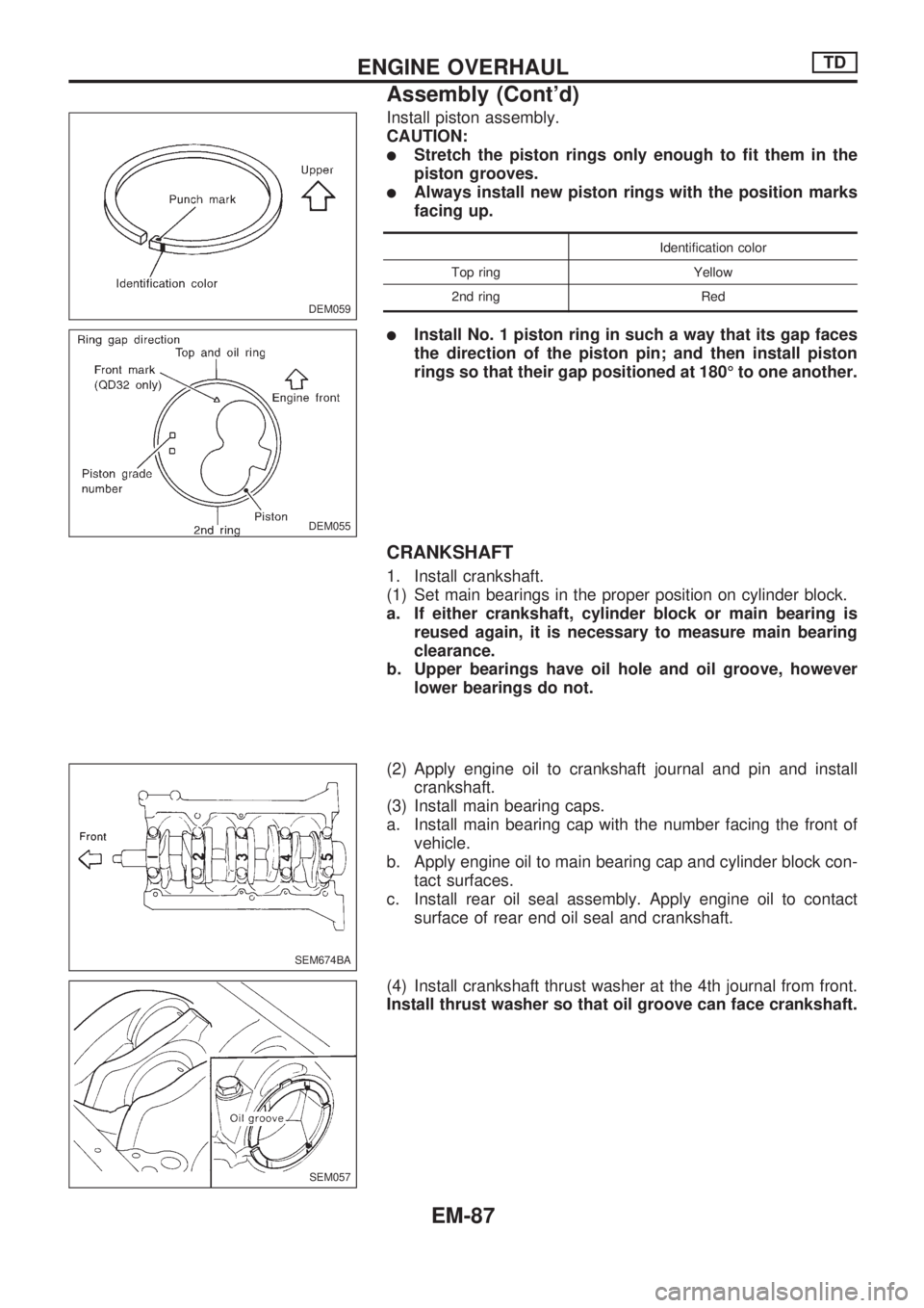
(5) Tighten main bearing cap bolts gradually in stages, starting
from two to three separate stages, from center bearing and
moving outward in sequence.
: 167 - 177 Nzm (17.0 - 18.0 kg-m, 123 - 130 ft-lb)
(6) Measure crankshaft free end play at No. 4 bearing.
Crankshaft free end play: mm (in)
Standard
0.055 - 0.140 (0.0022 - 0.0055)
Limit
0.40 (0.0157)
If beyond the limit, replace No. 4 main bearing thrust
washer. Refer to SDS, EM-106.
2. Install pistons with connecting rods.
(1) Install them into corresponding cylinder using Tool.
lBe careful not to scratch cylinder wall with connecting
rod.
lInsert the connecting rod. Do not allow the larger end to
touch the oil jet.
lApply engine oil to cylinder wall, piston and bearing.
lThe leaf type combustion chamber on piston head must
be at right side of engine.
(2) Install connecting rod bearing caps.
SEM675B
SEM677B
SEM063
DEM056.DEM056
SEM678B
ENGINE OVERHAULTD
Assembly (Cont'd)
EM-88
Page 1651 of 1659

General Specifications
Engine model TD25
Cylinder arrangementIn-line
Number of cylinders 4
Valve arrangement OHV
Bore x stroke mm (in)92.9 x 92.0
(3.657 x 3.622)
Displacement cm
3(cu in) 2,494 (152.18)
Firing order 1-3-4-2
Number of
piston ringsCompression 2
Oil 1
Number of main bearings 5
Inspection and Adjustment
COMPRESSION PRESSURE
Unit: kPa (bar, kg/cm2, psi)/rpm
Standard 2,942 (29.4, 30, 427)/200
Minimum 2,452 (24.5, 25, 356)/200
Differential limit between cylinders 294 (2.9, 3, 43)/200
CYLINDER HEAD
Unit: mm (in)
Standard Limit
Head surface distortionLess than
0.07 (0.0028)0.2 (0.008)
Nominal cylinder head height 89.9 - 90.1 (3.539 - 3.547)
VALVE
Unit: mm (in)
SEM188
Engine TD25
Valve head diameter ``D''
Intake41.4 - 41.6
(1.630 - 1.638)
Exhaust36.9 - 37.1
(1.453 - 1.461)
Valve length ``L''
Intake
117 (4.61)
Exhaust
Valve stem diameter ``d''
Intake 7.962 - 7.977 (0.3135 - 0.3141)
Exhaust 7.945 - 7.960 (0.3128 - 0.3134)
Valve seat angle ``a''
Intake
45É - 45É30¢
Exhaust
Valve margin ``T'' limit 0.5 (0.020)
Valve stem end surface
grinding limit0.2 (0.008)
Valve clearance (Hot)
Intake
0.35 (0.0138)
Exhaust
SERVICE DATA AND SPECIFICATIONS (SDS)TD
EM-98