Page 1615 of 1659
Assembly
1. Assemble rocker shaft component parts.
lFace punch mark toward the front of the engine.
Identification of rocker arms
Identification mark
(At area
Vaon rocker arm)For use with
Two ridges Intake
No ridge Exhaust
2. Install valve component parts.
Identification of valves
Identification mark
(on intake and exhaust valve)
Engine
Intake valve Exhaust valve
2 B TD25
lAlways use new valve oil seal. (Refer to EM-68.)
lInstall valve spring (uneven pitch type) with its narrow
pitch side toward cylinder head side.
DEM034
SEM066C
MEM180A
SEM615F
SEM638B
CYLINDER HEADTD
EM-62
Page 1617 of 1659
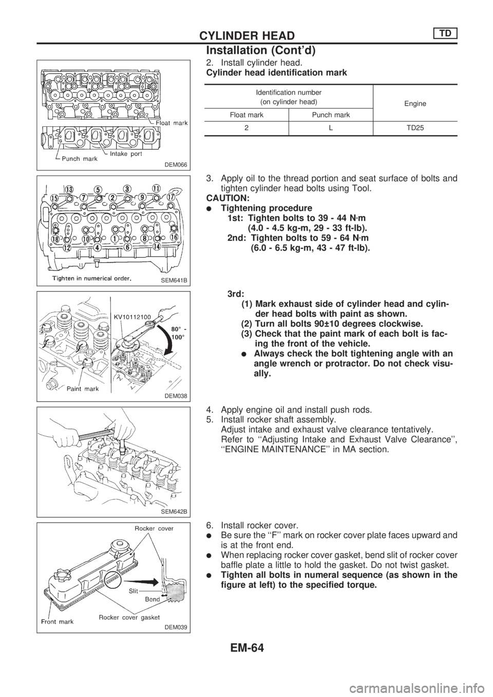
2. Install cylinder head.
Cylinder head identification mark
Identification number
(on cylinder head)
Engine
Float mark Punch mark
2 L TD25
3. Apply oil to the thread portion and seat surface of bolts and
tighten cylinder head bolts using Tool.
CAUTION:
lTightening procedure
1st: Tighten bolts to 39 - 44 Nzm
(4.0 - 4.5 kg-m, 29 - 33 ft-lb).
2nd: Tighten bolts to 59 - 64 Nzm
(6.0 - 6.5 kg-m, 43 - 47 ft-lb).
3rd:
(1) Mark exhaust side of cylinder head and cylin-
der head bolts with paint as shown.
(2) Turn all bolts 90 10 degrees clockwise.
(3) Check that the paint mark of each bolt is fac-
ing the front of the vehicle.
lAlways check the bolt tightening angle with an
angle wrench or protractor. Do not check visu-
ally.
4. Apply engine oil and install push rods.
5. Install rocker shaft assembly.
Adjust intake and exhaust valve clearance tentatively.
Refer to ``Adjusting Intake and Exhaust Valve Clearance'',
``ENGINE MAINTENANCE'' in MA section.
6. Install rocker cover.
lBe sure the ``F'' mark on rocker cover plate faces upward and
is at the front end.
lWhen replacing rocker cover gasket, bend slit of rocker cover
baffle plate a little to hold the gasket. Do not twist gasket.
lTighten all bolts in numeral sequence (as shown in the
figure at left) to the specified torque.
DEM066
SEM641B
DEM038
SEM642B
DEM039
CYLINDER HEADTD
Installation (Cont'd)
EM-64
Page 1620 of 1659
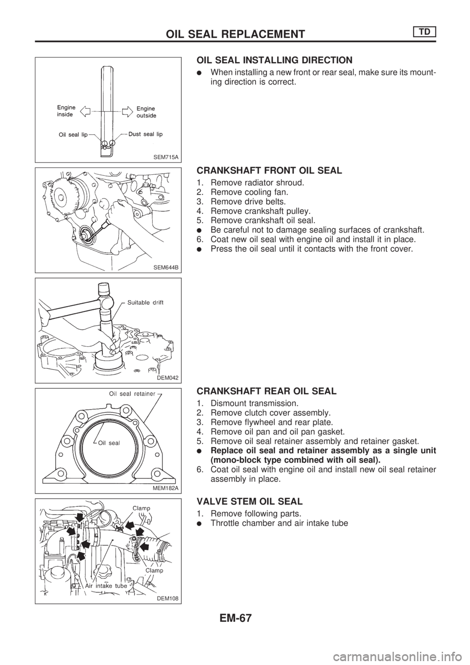
OIL SEAL INSTALLING DIRECTION
lWhen installing a new front or rear seal, make sure its mount-
ing direction is correct.
CRANKSHAFT FRONT OIL SEAL
1. Remove radiator shroud.
2. Remove cooling fan.
3. Remove drive belts.
4. Remove crankshaft pulley.
5. Remove crankshaft oil seal.
lBe careful not to damage sealing surfaces of crankshaft.
6. Coat new oil seal with engine oil and install it in place.
lPress the oil seal until it contacts with the front cover.
CRANKSHAFT REAR OIL SEAL
1. Dismount transmission.
2. Remove clutch cover assembly.
3. Remove flywheel and rear plate.
4. Remove oil pan and oil pan gasket.
5. Remove oil seal retainer assembly and retainer gasket.
lReplace oil seal and retainer assembly as a single unit
(mono-block type combined with oil seal).
6. Coat oil seal with engine oil and install new oil seal retainer
assembly in place.
VALVE STEM OIL SEAL
1. Remove following parts.
lThrottle chamber and air intake tube
SEM715A
SEM644B
DEM042
MEM182A
DEM108
.
OIL SEAL REPLACEMENTTD
EM-67
Page 1621 of 1659
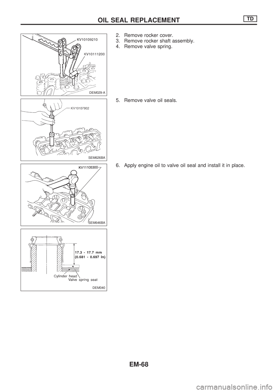
2. Remove rocker cover.
3. Remove rocker shaft assembly.
4. Remove valve spring.
5. Remove valve oil seals.
6. Apply engine oil to valve oil seal and install it in place.
DEM029-A
SEM626BA
SEM646BA
DEM040
OIL SEAL REPLACEMENTTD
EM-68
Page 1623 of 1659
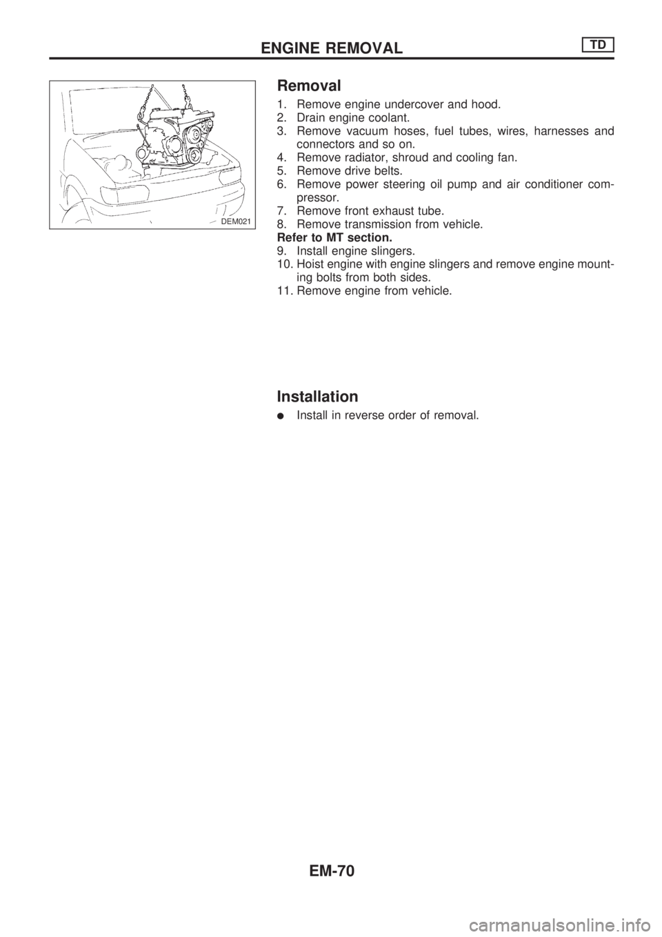
Removal
1. Remove engine undercover and hood.
2. Drain engine coolant.
3. Remove vacuum hoses, fuel tubes, wires, harnesses and
connectors and so on.
4. Remove radiator, shroud and cooling fan.
5. Remove drive belts.
6. Remove power steering oil pump and air conditioner com-
pressor.
7. Remove front exhaust tube.
8. Remove transmission from vehicle.
Refer to MT section.
9. Install engine slingers.
10. Hoist engine with engine slingers and remove engine mount-
ing bolts from both sides.
11. Remove engine from vehicle.
Installation
lInstall in reverse order of removal.
DEM021
ENGINE REMOVALTD
EM-70
Page 1625 of 1659
Disassembly
PISTON AND CRANKSHAFT
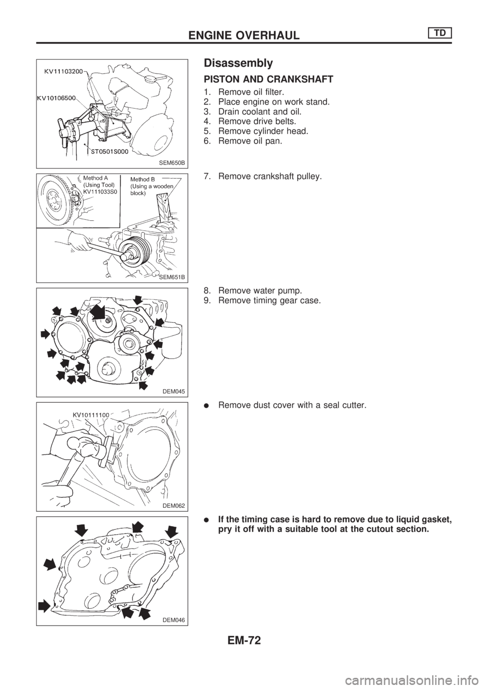
1. Remove oil filter.
2. Place engine on work stand.
3. Drain coolant and oil.
4. Remove drive belts.
5. Remove cylinder head.
6. Remove oil pan.
7. Remove crankshaft pulley.
8. Remove water pump.
9. Remove timing gear case.
lRemove dust cover with a seal cutter.
lIf the timing case is hard to remove due to liquid gasket,
pry it off with a suitable tool at the cutout section.
SEM650B
SEM651B
DEM045
DEM062
DEM046
ENGINE OVERHAULTD
EM-72
Page 1626 of 1659
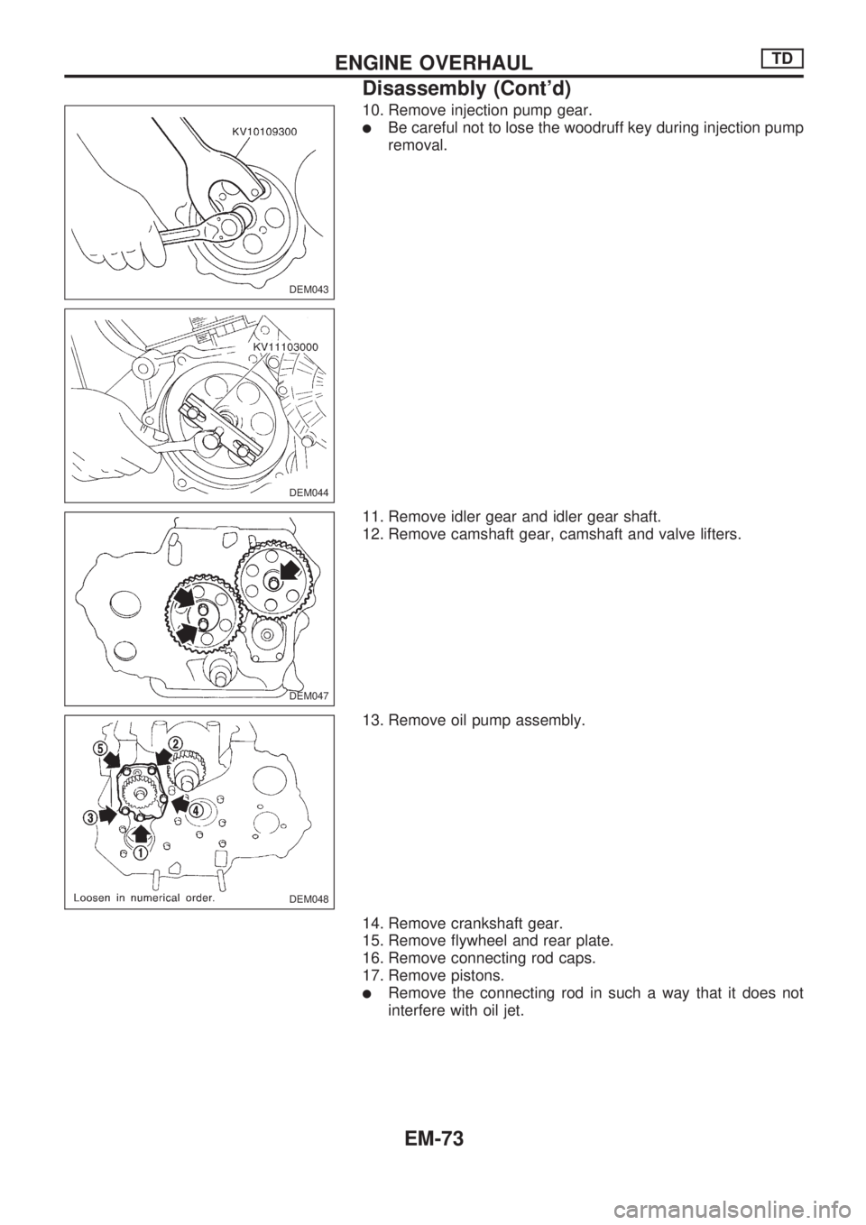
10. Remove injection pump gear.
lBe careful not to lose the woodruff key during injection pump
removal.
11. Remove idler gear and idler gear shaft.
12. Remove camshaft gear, camshaft and valve lifters.
13. Remove oil pump assembly.
14. Remove crankshaft gear.
15. Remove flywheel and rear plate.
16. Remove connecting rod caps.
17. Remove pistons.
lRemove the connecting rod in such a way that it does not
interfere with oil jet.
DEM043
DEM044
DEM047
DEM048
ENGINE OVERHAULTD
Disassembly (Cont'd)
EM-73
Page 1627 of 1659
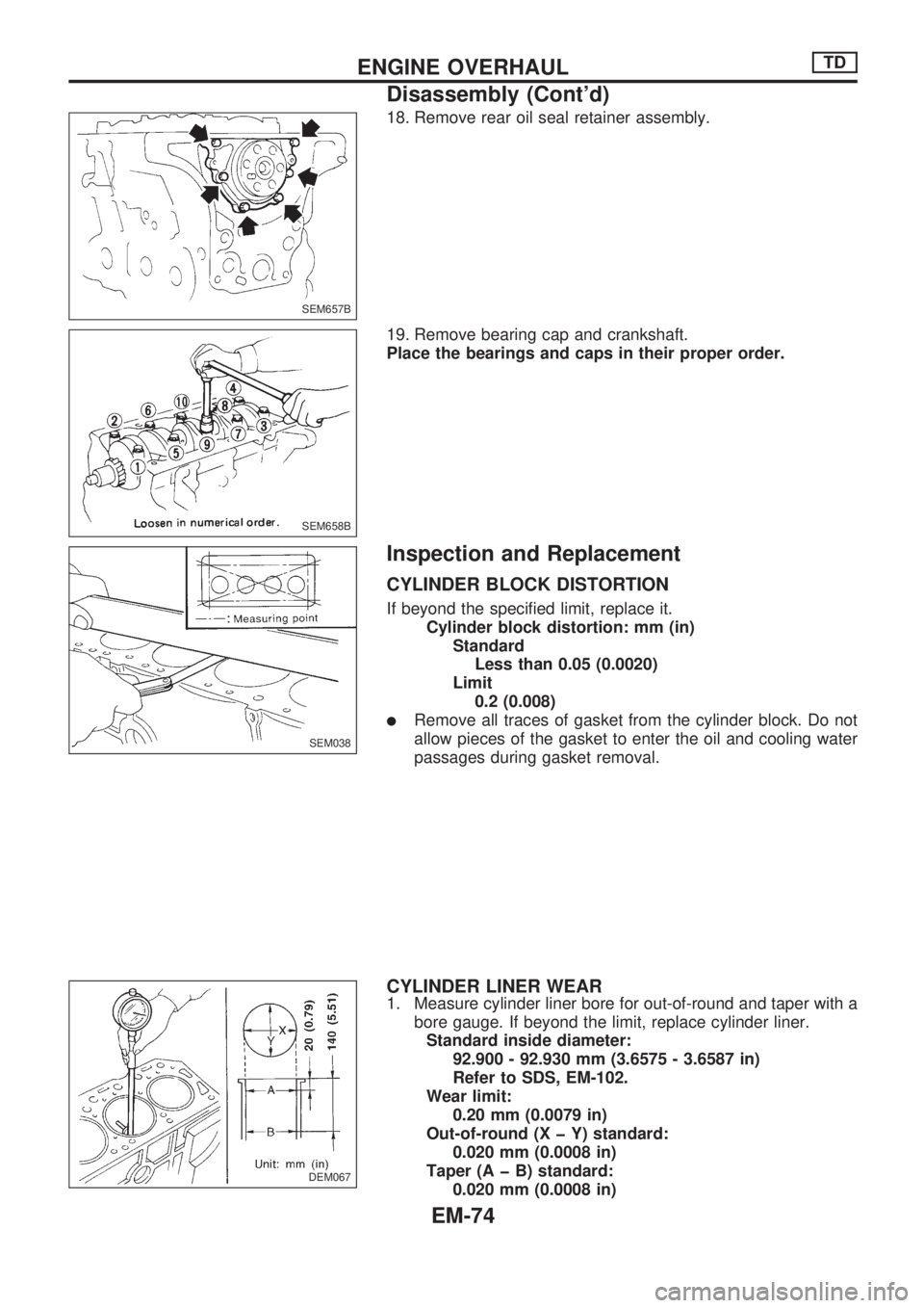
18. Remove rear oil seal retainer assembly.
19. Remove bearing cap and crankshaft.
Place the bearings and caps in their proper order.
Inspection and Replacement
CYLINDER BLOCK DISTORTION
If beyond the specified limit, replace it.
Cylinder block distortion: mm (in)
Standard
Less than 0.05 (0.0020)
Limit
0.2 (0.008)
lRemove all traces of gasket from the cylinder block. Do not
allow pieces of the gasket to enter the oil and cooling water
passages during gasket removal.
CYLINDER LINER WEAR
1. Measure cylinder liner bore for out-of-round and taper with a
bore gauge. If beyond the limit, replace cylinder liner.
Standard inside diameter:
92.900 - 92.930 mm (3.6575 - 3.6587 in)
Refer to SDS, EM-102.
Wear limit:
0.20 mm (0.0079 in)
Out-of-round (X þ Y) standard:
0.020 mm (0.0008 in)
Taper (A þ B) standard:
0.020 mm (0.0008 in)
SEM657B
SEM658B
SEM038
DEM067
ENGINE OVERHAULTD
Disassembly (Cont'd)
EM-74