1998 NISSAN PICK-UP Mass Air Flow Sensor
[x] Cancel search: Mass Air Flow SensorPage 151 of 1659

TROUBLE DIAGNOSIS FOR POWER SUPPLY.... 75
Main Power Supply and Ground Circuit .............. 75
TROUBLE DIAGNOSIS FOR ``CAMSHAFT
POSI SEN'' (DTC 11).............................................. 82
Camshaft Position Sensor (CMPS) ..................... 82
TROUBLE DIAGNOSIS FOR ``MASS AIR
FLOW SEN'' (DTC 12)............................................ 89
Mass Air Flow Sensor (MAFS) ............................ 89
TROUBLE DIAGNOSIS FOR ``COOLANT TEMP
SEN'' (DTC 13)........................................................ 95
Engine Coolant Temperature Sensor (ECTS) ..... 95
TROUBLE DIAGNOSIS FOR ``IGN SIGNAL-
PRIMARY'' (DTC 21)............................................... 99
Ignition Signal ...................................................... 99
TROUBLE DIAGNOSIS FOR ``OVER HEAT''
(DTC 28)................................................................. 106
Overheat ............................................................ 106
TROUBLE DIAGNOSIS FOR ``INT AIR TEMP
SEN'' (DTC 41)...................................................... 109
Intake Air Temperature Sensor ......................... 109
TROUBLE DIAGNOSIS FOR ``THROTTLE POSI
SEN'' (DTC 43)...................................................... 113
Throttle Position Sensor .................................... 113
TROUBLE DIAGNOSIS FOR
NON-DETECTABLE ITEMS.................................. 118
Vehicle Speed Sensor (VSS) ............................ 118
Heated Oxygen Sensor (HO2S)
- LHD Models - .................................................. 123
Heated Oxygen Sensor Heater
- LHD Models - .................................................. 127
Idle Air Control Valve (IACV) - Auxiliary Air
Control (AAC) Valve .......................................... 131
Neutral Position Switch ...................................... 136
EVAP Canister Purge Control Solenoid Valve .. 140
Injector ............................................................... 144
Start Signal ........................................................ 149
Fuel Pump.......................................................... 151
Power Steering Oil Pressure Switch ................. 157
Swirl Control Valve Control Solenoid Valve ...... 161
IACV-FICD Solenoid Valve ................................ 168
MIL & Data Link Connectors ............................. 173
TD
INJECTION SYSTEM............................................ 176
Fuel System ....................................................... 176
INJECTION PUMP................................................. 178
Inspection ........................................................... 178
Removal ............................................................. 178
Installation and Adjustment................................ 180
Disassembly ....................................................... 183
Load Timer Adjustment...................................... 183
Start Q Adjustment Lever .................................. 184
INJECTION NOZZLE............................................. 186Removal and Installation ................................... 186
Disassembly ....................................................... 186
Inspection ........................................................... 187
Cleaning ............................................................. 187
Assembly............................................................ 189
Test and Adjustment .......................................... 189
FUEL SYSTEM CHECK........................................ 191
Bleeding Fuel System ........................................ 191
Bleeding Fuel Filter ............................................ 192
Checking Priming Pump .................................... 192
Checking Fuel Filter Switch ............................... 192
POSITIVE CRANKCASE VENTILATION.............. 193
Description ......................................................... 193
Inspection ........................................................... 193
QUICK-GLOW SYSTEM........................................ 194
Component Parts Location ................................ 194
Circuit Diagram .................................................. 195
Description ......................................................... 196
Wiring Diagram .................................................. 197
Glow Control Unit Circuit Inspection (For Cold
Areas)................................................................. 203
Glow Control Unit Circuit Inspection (Except
for Cold Areas)................................................... 206
Component Inspection ....................................... 208
EGR SYSTEM........................................................ 210
Component Parts Location ................................ 210
Description ......................................................... 211
Operation ........................................................... 212
Wiring Diagram .................................................. 213
System Inspection.............................................. 217
Component Inspection ....................................... 218
SOLENOID TIMER................................................ 220
Description ......................................................... 220
Operation ........................................................... 220
Wiring Diagram .................................................. 222
Inspection ........................................................... 224
FUEL CUT SYSTEM.............................................. 225
Wiring Diagram .................................................. 225
FUEL HEATER SYSTEM...................................... 226
Description ......................................................... 226
Wiring Diagram .................................................. 227
System Inspection.............................................. 228
Component Inspection ....................................... 228
FAST IDLE CONTROL CIRCUIT.......................... 230
Wiring Diagram .................................................. 230
Electrical Components Inspection ..................... 231
KA
SERVICE DATA AND SPECIFICATIONS (SDS). 232
General Specifications ....................................... 232
Inspection and Adjustment ................................ 232
Page 165 of 1659

System Chart
Camshaft position sensorc
ECM
(ECCS
control
module)
Mass air flow sensorc
Engine coolant temperature sensorc
Heated oxygen sensor*c
Ignition switchc
Throttle position sensorc
Neutral position switchc
Vehicle speed sensorc
Air conditioner switchc
Battery voltagec
Power steering oil pressure switchc
Intake air temperature sensorc
*: LHD models
Fuel injection &
mixture ratio controlcInjectors
Distributor ignition systemcPower transistor
Idle air control systemcIACV-AAC valve
IACV-FICD solenoid valve
Swirl control valve controlcSwirl control valve control
solenoid valve
EVAP canister controlcEVAP canister purge control
solenoid valve
Fuel pump controlcFuel pump relay
Heated oxygen sensor moni-
tor & on board diagnostic
systemcMalfunction indicator lamp
(On the instrument panel)
Acceleration cut controlcAir conditioner relay
Heated oxygen sensor
heater control*cHeated oxygen sensor
heater
ENGINE AND EMISSION CONTROL OVERALL SYSTEMKA
EC-13
Page 166 of 1659

Multiport Fuel Injection (MFI) System
INPUT/OUTPUT SIGNAL LINE
Camshaft position sensorcEngine speed and piston position
ECM
(ECCS
control
module)
cInjector
Mass air flow sensorcAmount of intake air
Engine coolant temperature sensor
cEngine coolant temperature
Heated oxygen sensor*
cDensity of oxygen in exhaust gas
Throttle position sensor
cThrottle position
Throttle valve idle position
Neutral position switch
cGear position
Vehicle speed sensor
cVehicle speed
Ignition switch
cStart signal
Battery
cBattery voltage
*: LHD models
BASIC MULTIPORT FUEL INJECTION
SYSTEM
The amount of fuel injected from the fuel injector is
determined by the ECM. The ECM controls the
length of time the valve remains open (injection
pulse duration). The amount of fuel injected is a
program value in the ECM memory. The program
value is preset by engine operating conditions.
These conditions are determined by input signals
(for engine speed and intake air) from both the
camshaft position sensor and the mass air flow
sensor.
VARIOUS FUEL INJECTION
INCREASE/DECREASE COMPENSATION
The amount of fuel injected is compensated for to
improve engine performance. This will be made
under various operating conditions as listed below.
lDuring warm-up
lWhen starting the engine
lDuring acceleration
lHot-engine operation
lHigh-load, high-speed operation
lWhen swirl control valve operates
lDuring deceleration
lDuring high-engine speed operation
lExtremely high-engine coolant temperature
ENGINE AND EMISSION BASIC CONTROL SYSTEM DESCRIPTIONKA
EC-14
Page 167 of 1659

MIXTURE RATIO FEEDBACK CONTROL
The mixture ratio feedback system provides the best air-fuel
mixture ratio for driveability and emission control. The three way
catalyst can then better reduce CO, HC and NOx emissions. This
system uses a heated oxygen sensor in the exhaust manifold to
monitor if the engine is rich or lean. The ECM adjusts the injec-
tion pulse width according to the sensor voltage signal. For more
information about heated oxygen sensor, refer to page EC-123.
This maintains the mixture ratio within the range of stoichiomet-
ric (ideal air-fuel mixture).
This stage is referred to as the closed loop control condition.
OPEN LOOP CONTROL
The open loop system condition refers to when the ECM detects
any of the following conditions. Feedback control stops in order
to maintain stabilized fuel combustion.
lDeceleration and acceleration
lHigh-load, high-speed operation
lEngine idling
lMalfunction of heated oxygen sensor or its circuit
lInsufficient activation of heated oxygen sensor at low engine
coolant temperature
lHigh-engine coolant temperature
lDuring warm-up
lWhen starting the engine
MIXTURE RATIO SELF-LEARNING CONTROL
The mixture ratio feedback control system monitors the mixture
ratio signal transmitted from the heated oxygen sensor. This
feedback signal is then sent to the ECM. The ECM controls the
basic mixture ratio as close to the theoretical mixture ratio as
possible. However, the basic mixture ratio is not necessarily con-
trolled as originally designed. Both Manufacturing differences
(i.e. mass air flow sensor hot wire) and characteristic changes
during operation (i.e. injector clogging) directly affect mixture
ratio.
Accordingly, the difference between the basic and theoretical
mixture ratios is monitored in this system. This is then computed
in terms of ``injection pulse duration'' to automatically compen-
sate for the difference between the two ratios.
FUEL INJECTION SYSTEM
Two types of systems are used.
Sequential multiport fuel injection system
Fuel is injected into each cylinder during each engine cycle
according to the firing order. This system is used when the
engine is running.
MEF025DD
MEF522D
ENGINE AND EMISSION BASIC CONTROL SYSTEM DESCRIPTIONKA
Multiport Fuel Injection (MFI) System
(Cont'd)
EC-15
Page 169 of 1659

Distributor Ignition (DI) System
INPUT/OUTPUT SIGNAL LINE
Camshaft position sensorcEngine speed and piston position
ECM
(ECCS
control
module)
cPower
transistor
Mass air flow sensorcAmount of intake air
Engine coolant temperature sensor
cEngine coolant temperature
Throttle position sensor
c
Throttle position
Throttle valve idle position
Vehicle speed sensor
cVehicle speed
Ignition switch
cStart signal
Intake air temperature sensor
cIntake air temperature
Neutral position switch
cGear position
Battery
cBattery voltage
SYSTEM DESCRIPTION
The ignition timing is controlled by the ECM to maintain the best
air-fuel ratio for every running condition of the engine.
The ignition timing data is stored in the ECM. This data forms the
map shown left.
The ECM detects information such as the injection pulse width
and camshaft position sensor signal. Responding to this
information, ignition signals are transmitted to the power transis-
tor.
e.g. N: 1,800 rpm, Tp: 1.50 msec
A ÉBTDC
During the following conditions, the ignition timing is revised by
the ECM according to the other data stored in the ECM.
1 At starting
2 During warm-up
3 At idle
4 When swirl control valve operates
5 Hot-engine operation
6 At acceleration
SEF742M
ENGINE AND EMISSION BASIC CONTROL SYSTEM DESCRIPTIONKA
EC-17
Page 182 of 1659
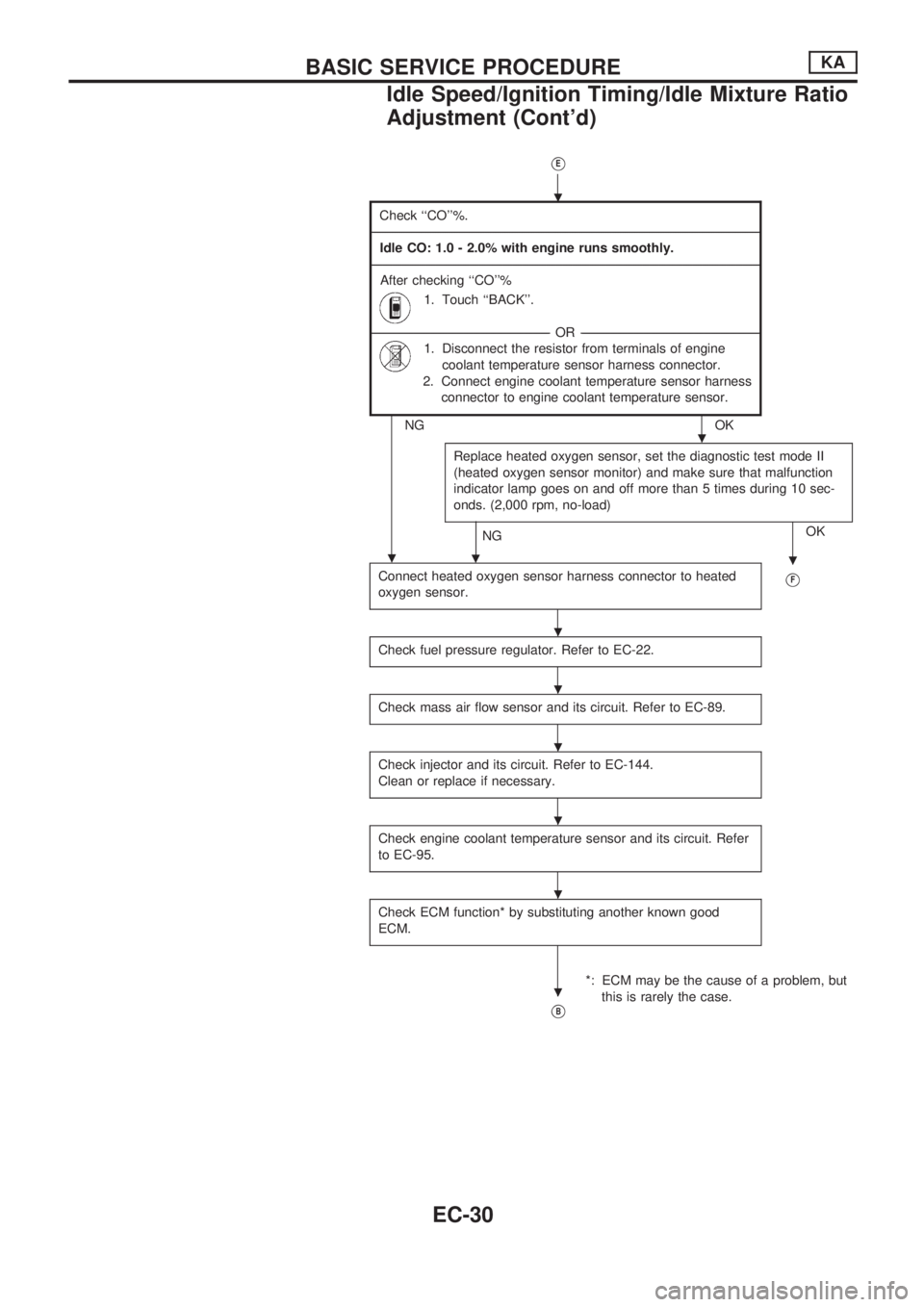
VE
Check ``CO''%.
-------------------------------------------------------------------------------------------------------------------------------------------------------------------------------------------------------------------------------------------------------------------------------------------------------------------------------------------------------------------------------------------------------------------------------------------------------
Idle CO: 1.0 - 2.0% with engine runs smoothly.
-------------------------------------------------------------------------------------------------------------------------------------------------------------------------------------------------------------------------------------------------------------------------------------------------------------------------------------------------------------------------------------------------------------------------------------------------------
After checking ``CO''%
1. Touch ``BACK''.
---------------------------------------------------------------------------------------------------------------------------------------------------------------------------------------------------------OR---------------------------------------------------------------------------------------------------------------------------------------------------------------------------------------------------------
1. Disconnect the resistor from terminals of engine
coolant temperature sensor harness connector.
2. Connect engine coolant temperature sensor harness
connector to engine coolant temperature sensor.
NG OK
Replace heated oxygen sensor, set the diagnostic test mode II
(heated oxygen sensor monitor) and make sure that malfunction
indicator lamp goes on and off more than 5 times during 10 sec-
onds. (2,000 rpm, no-load)
NGOK
.
Connect heated oxygen sensor harness connector to heated
oxygen sensor.VF
Check fuel pressure regulator. Refer to EC-22.
Check mass air flow sensor and its circuit. Refer to EC-89.
Check injector and its circuit. Refer to EC-144.
Clean or replace if necessary.
Check engine coolant temperature sensor and its circuit. Refer
to EC-95.
Check ECM function* by substituting another known good
ECM.
*: ECM may be the cause of a problem, but
this is rarely the case.
VB
.
.
..
.
.
.
.
.
.
BASIC SERVICE PROCEDUREKA
Idle Speed/Ignition Timing/Idle Mixture Ratio
Adjustment (Cont'd)
EC-30
Page 199 of 1659
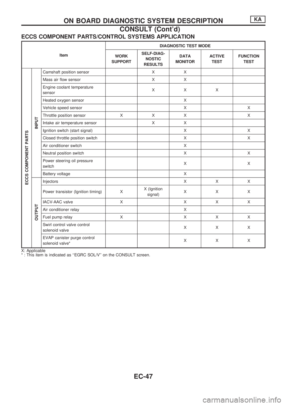
ECCS COMPONENT PARTS/CONTROL SYSTEMS APPLICATION
ItemDIAGNOSTIC TEST MODE
WORK
SUPPORTSELF-DIAG-
NOSTIC
RESULTSDATA
MONITORACTIVE
TESTFUNCTION
TEST
ECCS COMPONENT PARTS
INPUT
Camshaft position sensor X X
Mass air flow sensor X X
Engine coolant temperature
sensorXXX
Heated oxygen sensor X
Vehicle speed sensor X X
Throttle position sensor X X X X
Intake air temperature sensor X X
Ignition switch (start signal) X X
Closed throttle position switch X X
Air conditioner switch X
Neutral position switch X X
Power steering oil pressure
switchXX
Battery voltage X
OUTPUT
Injectors X X X
Power transistor (Ignition timing) XX (Ignition
signal)XXX
IACV-AAC valve X X X X
Air conditioner relay X
Fuel pump relay X X X X
Swirl control valve control
solenoid valveXXX
EVAP canister purge control
solenoid valve*XXX
X: Applicable
* : This item is indicated as ``EGRC SOL/V'' on the CONSULT screen.
ON BOARD DIAGNOSTIC SYSTEM DESCRIPTIONKA
CONSULT (Cont'd)
EC-47
Page 200 of 1659
![NISSAN PICK-UP 1998 Repair Manual SELF-DIAGNOSTIC MODE
Regarding items detected in ``SELF-DIAG RESULTS mode, refer to ``DIAGNOSTIC TROUBLE CODE
INDEX, EC-1.
DATA MONITOR MODE
Monitored item
[Unit]ECM
input
signalsMain
signalsDescr](/manual-img/5/57374/w960_57374-199.png "NISSAN PICK-UP 1998 Repair Manual SELF-DIAGNOSTIC MODE
Regarding items detected in ``SELF-DIAG RESULTS mode, refer to ``DIAGNOSTIC TROUBLE CODE
INDEX, EC-1.
DATA MONITOR MODE
Monitored item
[Unit]ECM
input
signalsMain
signalsDescr")
SELF-DIAGNOSTIC MODE
Regarding items detected in ``SELF-DIAG RESULTS'' mode, refer to ``DIAGNOSTIC TROUBLE CODE
INDEX'', EC-1.
DATA MONITOR MODE
Monitored item
[Unit]ECM
input
signalsMain
signalsDescription Remarks
CMPSRPM
(POS) [rpm]
jj
lIndicates the engine speed computed
from the POS signal (1É signal) of the
camshaft position sensor.
MAS AIR/FL SE [V]
jjlThe signal voltage of the mass air flow
sensor is displayed.lWhen the engine is stopped, a certain
value is indicated.
COOLAN TEMP/S
[ÉC] or [ÉF]
jj
lThe engine coolant temperature (deter-
mined by the signal voltage of the engine
coolant temperature sensor) is displayed.lWhen the engine coolant temperature
sensor is open or short-circuited, ECM
enters fail-safe mode. The engine coolant
temperature determined by the ECM is
displayed.
O2 SEN [V]
jjlThe signal voltage of the heated oxygen
sensor is displayed.lLHD models only
M/R F/C MNT
[RICH/LEAN]
jj
lDisplay of heated oxygen sensor signal
during air-fuel ratio feedback control:
RICH ... means the mixture became
``rich'', and control is being affected
toward a leaner mixture.
LEAN ... means the mixture became
``lean'', and control is being affected
toward a rich mixture.lAfter turning ON the ignition switch,
``RICH'' is displayed until air-fuel mixture
ratio feedback control begins.
lWhen the air-fuel ratio feedback is
clamped, the value just before the clamp-
ing is displayed continuously.
lLHD models only
VHCL SPEED SE
[km/h] or [mph]
jjlThe vehicle speed computed from the
vehicle speed sensor signal is displayed.
BATTERY VOLT [V]
jjlThe power supply voltage of ECM is dis-
played.
THRTL POS SEN [V]
jjlThe throttle position sensor signal volt-
age is displayed.
INT/A TEMP SE
[ÉC] or [ÉF]
j
lThe intake air temperature (determined
by the signal voltage of the intake air
temperature sensor) is indicated.
START SIGNAL
[ON/OFF]
jjlIndicates [ON/OFF] condition from the
starter signal.lAfter starting the engine, [OFF] is
displayed regardless of the starter signal.
CLSD THL/POSI
[ON/OFF]
jj
lIndicates [ON/OFF] condition from the
throttle position sensor signal.
AIR COND SIG
[ON/OFF]
jj
lIndicates [ON/OFF] condition of the air
conditioner switch as determined by the
air conditioner signal.
P/N POSI SW
[ON/OFF]
jj
lIndicates [ON/OFF] condition from the
park/neutral position switch signal.
PW/ST SIGNAL
[ON/OFF]
jj
l[ON/OFF] condition of the power steering
oil pressure switch determined by the
power steering oil pressure signal is indi-
cated.
NOTE:
Any monitored item that does not match the vehicle being diagnosed is deleted from the display automatically.
ON BOARD DIAGNOSTIC SYSTEM DESCRIPTIONKA
CONSULT (Cont'd)
EC-48