Page 242 of 1659

DIAGNOSTIC TROUBLE CODE CONFIRMATION
PROCEDURE
1) Turn ignition switch ``ON'', and wait at least 6 seconds.
2) Select ``DATA MONITOR'' mode with CONSULT.
3) Start engine and wait at least 3 seconds.
-------------------------------------------------------------------------------------------------------------------------------------------------------------------------------------------------------------------------------------------------OR-------------------------------------------------------------------------------------------------------------------------------------------------------------------------------------------------------------------------------------------------
1) Turn ignition switch ``ON'', and wait at least 6 seconds.
2) Start engine and wait at least 3 seconds.
3) Turn ignition switch ``OFF'', wait at least 5 seconds and
then turn ``ON''.
4) Perform ``Diagnostic Test Mode II (Self-diagnostic
results)'' with ECM.
SEF078U
TROUBLE DIAGNOSIS FOR ``MASS AIR FLOW SEN'' (DTC 12)KA
Mass Air Flow Sensor (MAFS) (Cont'd)
EC-90
Page 243 of 1659
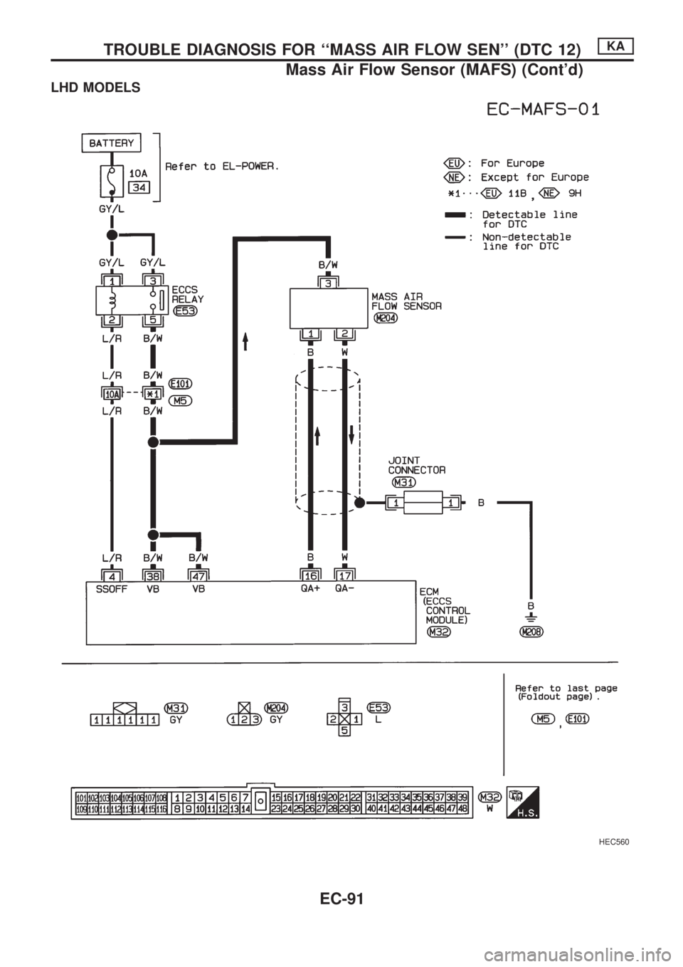
LHD MODELS
HEC560
TROUBLE DIAGNOSIS FOR ``MASS AIR FLOW SEN'' (DTC 12)KA
Mass Air Flow Sensor (MAFS) (Cont'd)
EC-91
Page 244 of 1659
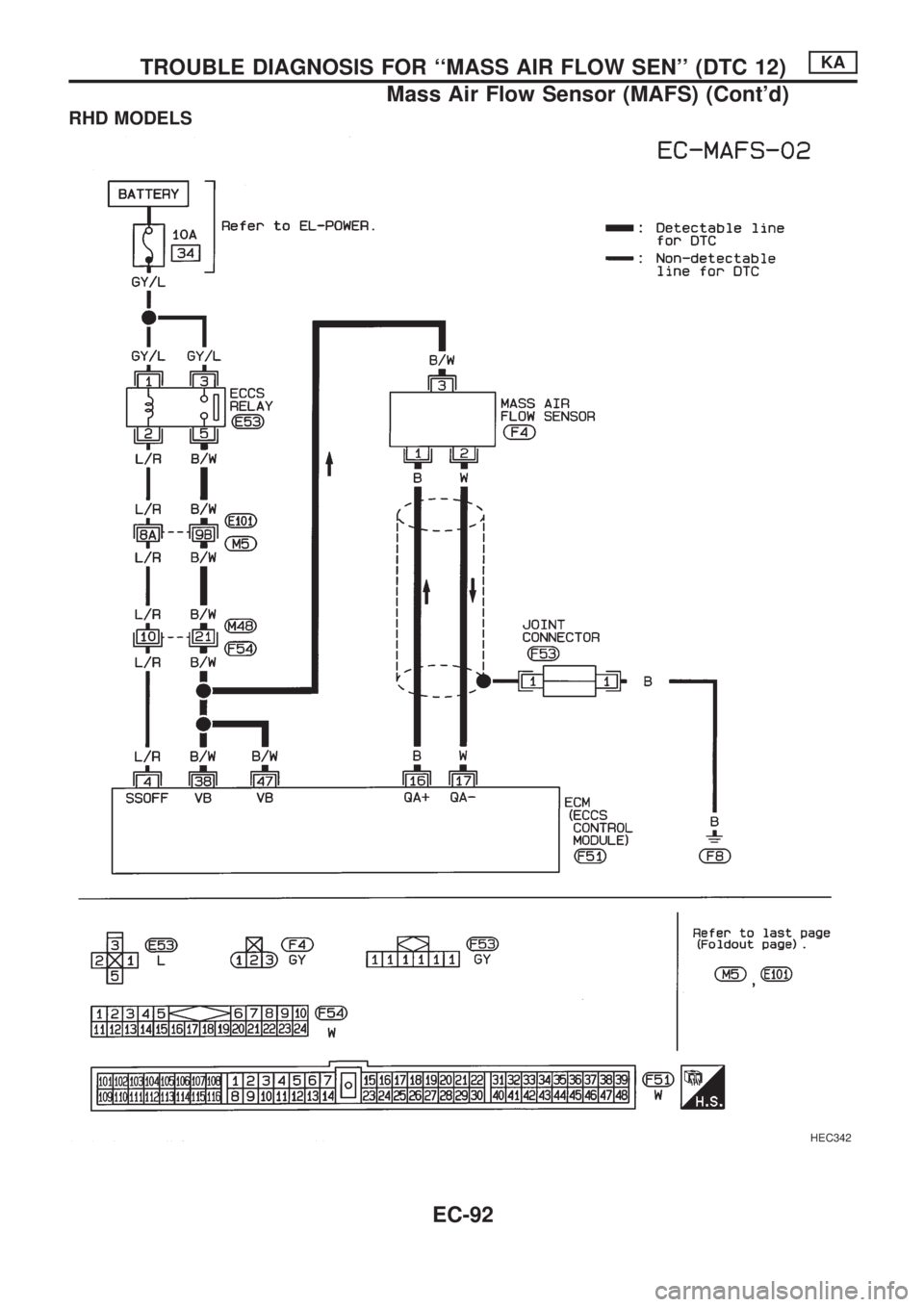
RHD MODELS
HEC342
TROUBLE DIAGNOSIS FOR ``MASS AIR FLOW SEN'' (DTC 12)KA
Mass Air Flow Sensor (MAFS) (Cont'd)
EC-92
Page 245 of 1659
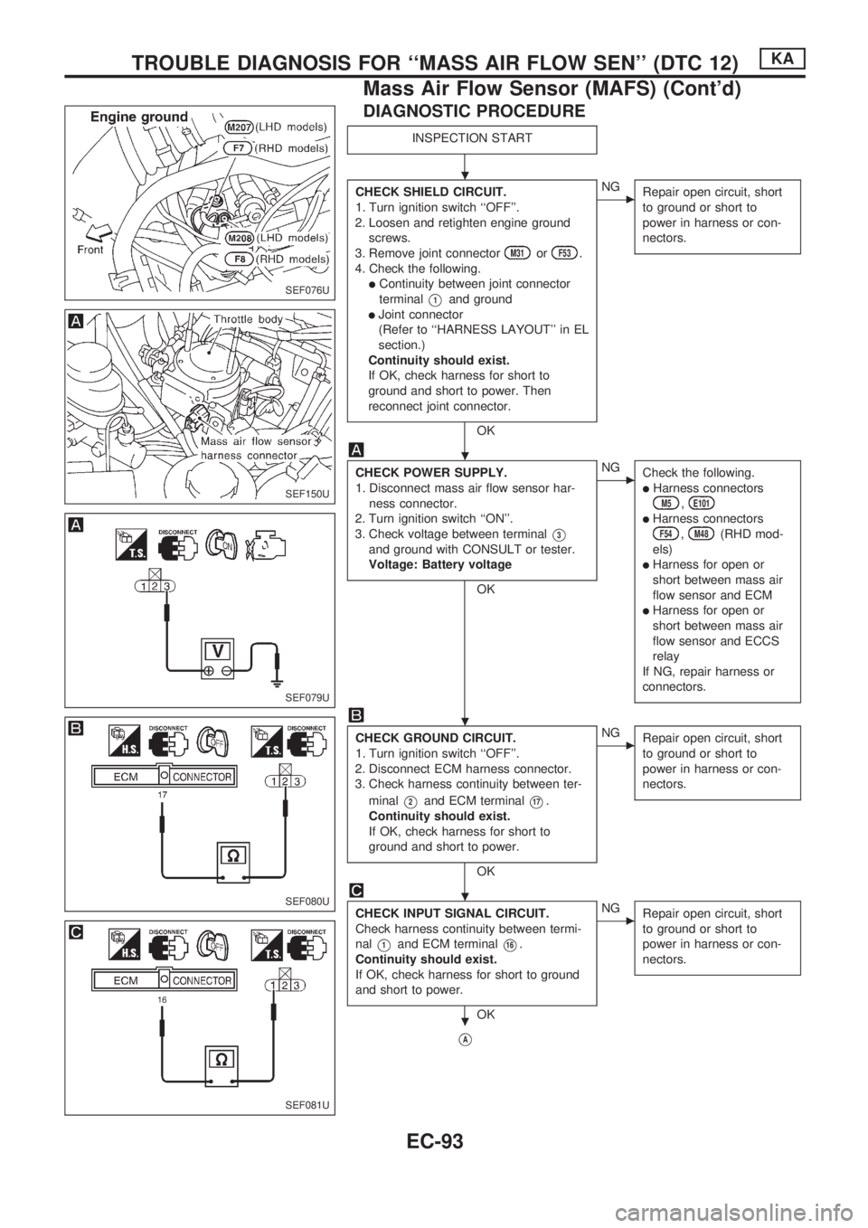
DIAGNOSTIC PROCEDURE
INSPECTION START
CHECK SHIELD CIRCUIT.
1. Turn ignition switch ``OFF''.
2. Loosen and retighten engine ground
screws.
3. Remove joint connector
M31orF53.
4. Check the following.
lContinuity between joint connector
terminal
V1and ground
lJoint connector
(Refer to ``HARNESS LAYOUT'' in EL
section.)
Continuity should exist.
If OK, check harness for short to
ground and short to power. Then
reconnect joint connector.
OK
cNG
Repair open circuit, short
to ground or short to
power in harness or con-
nectors.
CHECK POWER SUPPLY.
1. Disconnect mass air flow sensor har-
ness connector.
2. Turn ignition switch ``ON''.
3. Check voltage between terminal
V3
and ground with CONSULT or tester.
Voltage: Battery voltage
OK
cNG
Check the following.
lHarness connectorsM5,E101
lHarness connectorsF54,M48(RHD mod-
els)
lHarness for open or
short between mass air
flow sensor and ECM
lHarness for open or
short between mass air
flow sensor and ECCS
relay
If NG, repair harness or
connectors.
CHECK GROUND CIRCUIT.
1. Turn ignition switch ``OFF''.
2. Disconnect ECM harness connector.
3. Check harness continuity between ter-
minal
V2and ECM terminalV17.
Continuity should exist.
If OK, check harness for short to
ground and short to power.
OK
cNG
Repair open circuit, short
to ground or short to
power in harness or con-
nectors.
CHECK INPUT SIGNAL CIRCUIT.
Check harness continuity between termi-
nal
V1and ECM terminalV16.
Continuity should exist.
If OK, check harness for short to ground
and short to power.
OK
cNG
Repair open circuit, short
to ground or short to
power in harness or con-
nectors.
VA
SEF076U
SEF150U
SEF079U
SEF080U
SEF081U
.
.
.
.
.
TROUBLE DIAGNOSIS FOR ``MASS AIR FLOW SEN'' (DTC 12)KA
Mass Air Flow Sensor (MAFS) (Cont'd)
EC-93
Page 246 of 1659
VA
CHECK COMPONENT
(Mass air flow sensor).
Refer to ``COMPONENT INSPECTION''
below.
OK
cNG
Replace mass air flow
sensor.
Disconnect and reconnect harness con-
nectors in the circuits. Then retest.
Trouble is not fixed.
Check ECM pin terminals for damage
and check the connection of ECM har-
ness connector. Reconnect ECM harness
connector and retest.
INSPECTION END
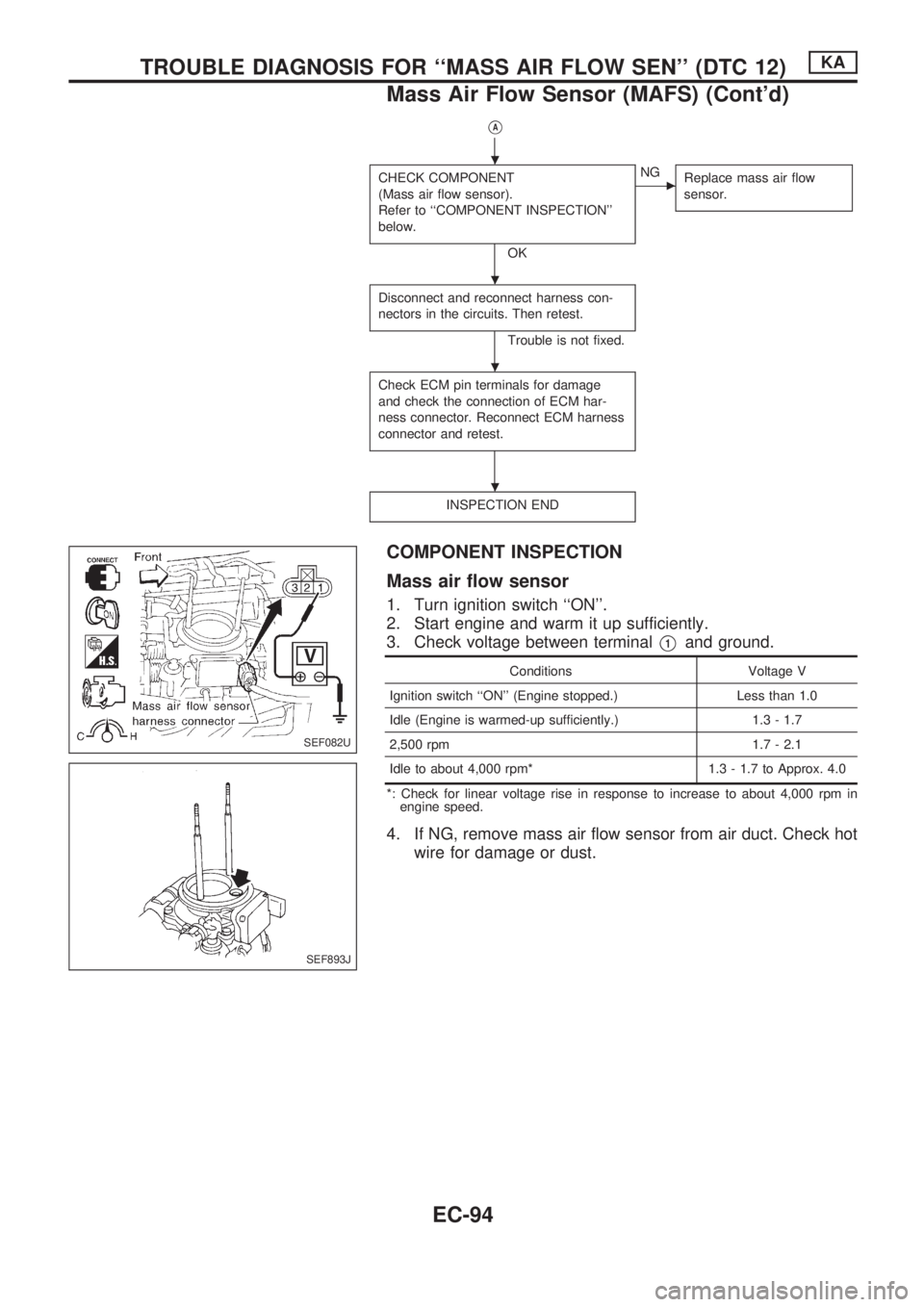
COMPONENT INSPECTION
Mass air flow sensor
1. Turn ignition switch ``ON''.
2. Start engine and warm it up sufficiently.
3. Check voltage between terminal
V1and ground.
Conditions Voltage V
Ignition switch ``ON'' (Engine stopped.) Less than 1.0
Idle (Engine is warmed-up sufficiently.) 1.3 - 1.7
2,500 rpm 1.7 - 2.1
Idle to about 4,000 rpm* 1.3 - 1.7 to Approx. 4.0
*: Check for linear voltage rise in response to increase to about 4,000 rpm in
engine speed.
4. If NG, remove mass air flow sensor from air duct. Check hot
wire for damage or dust.
SEF082U
SEF893J
.
.
.
.
TROUBLE DIAGNOSIS FOR ``MASS AIR FLOW SEN'' (DTC 12)KA
Mass Air Flow Sensor (MAFS) (Cont'd)
EC-94
Page 266 of 1659
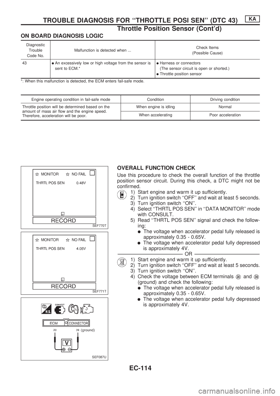
ON BOARD DIAGNOSIS LOGIC
Diagnostic
Trouble
Code No.Malfunction is detected when ...Check Items
(Possible Cause)
43
lAn excessively low or high voltage from the sensor is
sent to ECM.*lHarness or connectors
(The sensor circuit is open or shorted.)
lThrottle position sensor
*: When this malfunction is detected, the ECM enters fail-safe mode.
Engine operating condition in fail-safe mode Condition Driving condition
Throttle position will be determined based on the
amount of mass air flow and the engine speed.
Therefore, acceleration will be poor.When engine is idling Normal
When accelerating Poor acceleration
OVERALL FUNCTION CHECK
Use this procedure to check the overall function of the throttle
position sensor circuit. During this check, a DTC might not be
confirmed.
1) Start engine and warm it up sufficiently.
2) Turn ignition switch ``OFF'' and wait at least 5 seconds.
3) Turn ignition switch ``ON''.
4) Select ``THRTL POS SEN'' in ``DATA MONITOR'' mode
with CONSULT.
5) Read ``THRTL POS SEN'' signal and check the follow-
ing:
lThe voltage when accelerator pedal fully released is
approximately 0.35 - 0.65V.
lThe voltage when accelerator pedal fully depressed
is approximately 4V.
-------------------------------------------------------------------------------------------------------------------------------------------------------------------------------------------------------------------------------------------------OR-------------------------------------------------------------------------------------------------------------------------------------------------------------------------------------------------------------------------------------------------
1) Start engine and warm it up sufficiently.
2) Turn ignition switch ``OFF'' and wait at least 5 seconds.
3) Turn ignition switch ``ON''.
4) Check the voltage between ECM terminals
V20andV39
(ground) and check the following:
lThe voltage when accelerator pedal fully released is
approximately 0.35 - 0.65V.
lThe voltage when accelerator pedal fully depressed
is approximately 4V.
SEF770T
SEF771T
SEF087U
TROUBLE DIAGNOSIS FOR ``THROTTLE POSI SEN'' (DTC 43)KA
Throttle Position Sensor (Cont'd)
EC-114
Page 283 of 1659
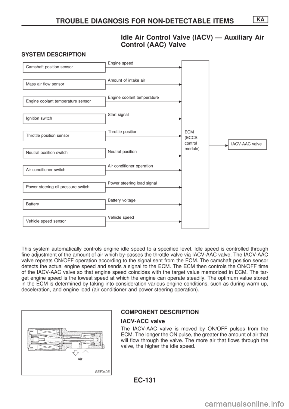
Idle Air Control Valve (IACV) Ð Auxiliary Air
Control (AAC) Valve
SYSTEM DESCRIPTION
Camshaft position sensorcEngine speed
ECM
(ECCS
control
module)
cIACV-AAC valve
Mass air flow sensorcAmount of intake air
Engine coolant temperature sensor
cEngine coolant temperature
Ignition switch
cStart signal
Throttle position sensor
cThrottle position
Neutral position switch
cNeutral position
Air conditioner switch
cAir conditioner operation
Power steering oil pressure switch
cPower steering load signal
Battery
cBattery voltage
Vehicle speed sensor
cVehicle speed
This system automatically controls engine idle speed to a specified level. Idle speed is controlled through
fine adjustment of the amount of air which by-passes the throttle valve via IACV-AAC valve. The IACV-AAC
valve repeats ON/OFF operation according to the signal sent from the ECM. The camshaft position sensor
detects the actual engine speed and sends a signal to the ECM. The ECM then controls the ON/OFF time
of the IACV-AAC valve so that engine speed coincides with the target value memorized in ECM. The tar-
get engine speed is the lowest speed at which the engine can operate steadily. The optimum value stored
in the ECM is determined by taking into consideration various engine conditions, such as during warm up,
deceleration, and engine load (air conditioner and power steering operation).
COMPONENT DESCRIPTION
IACV-ACC valve
The IACV-AAC valve is moved by ON/OFF pulses from the
ECM. The longer the ON pulse, the greater the amount of air that
will flow through the valve. The more air that flows through the
valve, the higher the idle speed.
SEF040E
TROUBLE DIAGNOSIS FOR NON-DETECTABLE ITEMSKA
EC-131
Page 313 of 1659
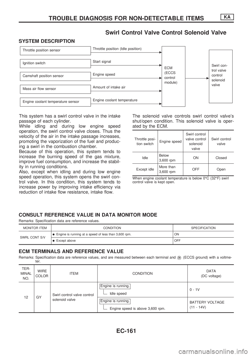
Swirl Control Valve Control Solenoid Valve
SYSTEM DESCRIPTION
Throttle position sensorcThrottle position (Idle position)
ECM
(ECCS
control
module)
c
Swirl con-
trol valve
control
solenoid
valveIgnition switchcStart signal
Camshaft position sensor
cEngine speed
Mass air flow sensor
cAmount of intake air
Engine coolant temperature sensor
cEngine coolant temperature
This system has a swirl control valve in the intake
passage of each cylinder.
While idling and during low engine speed
operation, the swirl control valve closes. Thus the
velocity of the air in the intake passage increases,
promoting the vaporization of the fuel and produc-
ing a swirl in the combustion chamber.
Because of this operation, this system tends to
increase the burning speed of the gas mixture,
improve fuel consumption, and increase the stabil-
ity in running conditions.
Also, except when idling and during low engine
speed operation, this system opens the swirl con-
trol valve. In this condition, this system tends to
increase power by improving intake efficiency via
reduction of intake flow resistance, intake flow.The solenoid valve controls swirl control valve's
shut/open condition. This solenoid valve is oper-
ated by the ECM.
Throttle posi-
tion switchEngine speedSwirl control
valve control
solenoid
valveSwirl control
valve
IdleBelow
3,600 rpmON Closed
Except idleMore than
3,600 rpmOFF Open
When engine coolant temperature is below 0ÉC (32ÉF) swirl
control valve is kept open.
CONSULT REFERENCE VALUE IN DATA MONITOR MODE
Remarks: Specification data are reference values.
MONITOR ITEM CONDITION SPECIFICATION
SWRL CONT S/V
lEngine is running at a speed of less than 3,600 rpm. ON
lExcept above OFF
ECM TERMINALS AND REFERENCE VALUE
Remarks: Specification data are reference values, and are measured between each terminal andV39(ECCS ground) with a voltme-
ter.
TER-
MINAL
NO.WIRE
COLORITEM CONDITIONDATA
(DC voltage)
12 GYSwirl control valve control
solenoid valveEngine is running.
Idle speed0-1V
Engine is running.
Engine speed is above 3,600 rpm.BATTERY VOLTAGE
(11 - 14V)
TROUBLE DIAGNOSIS FOR NON-DETECTABLE ITEMSKA
EC-161