1998 NISSAN PICK-UP thermostat
[x] Cancel search: thermostatPage 215 of 1659
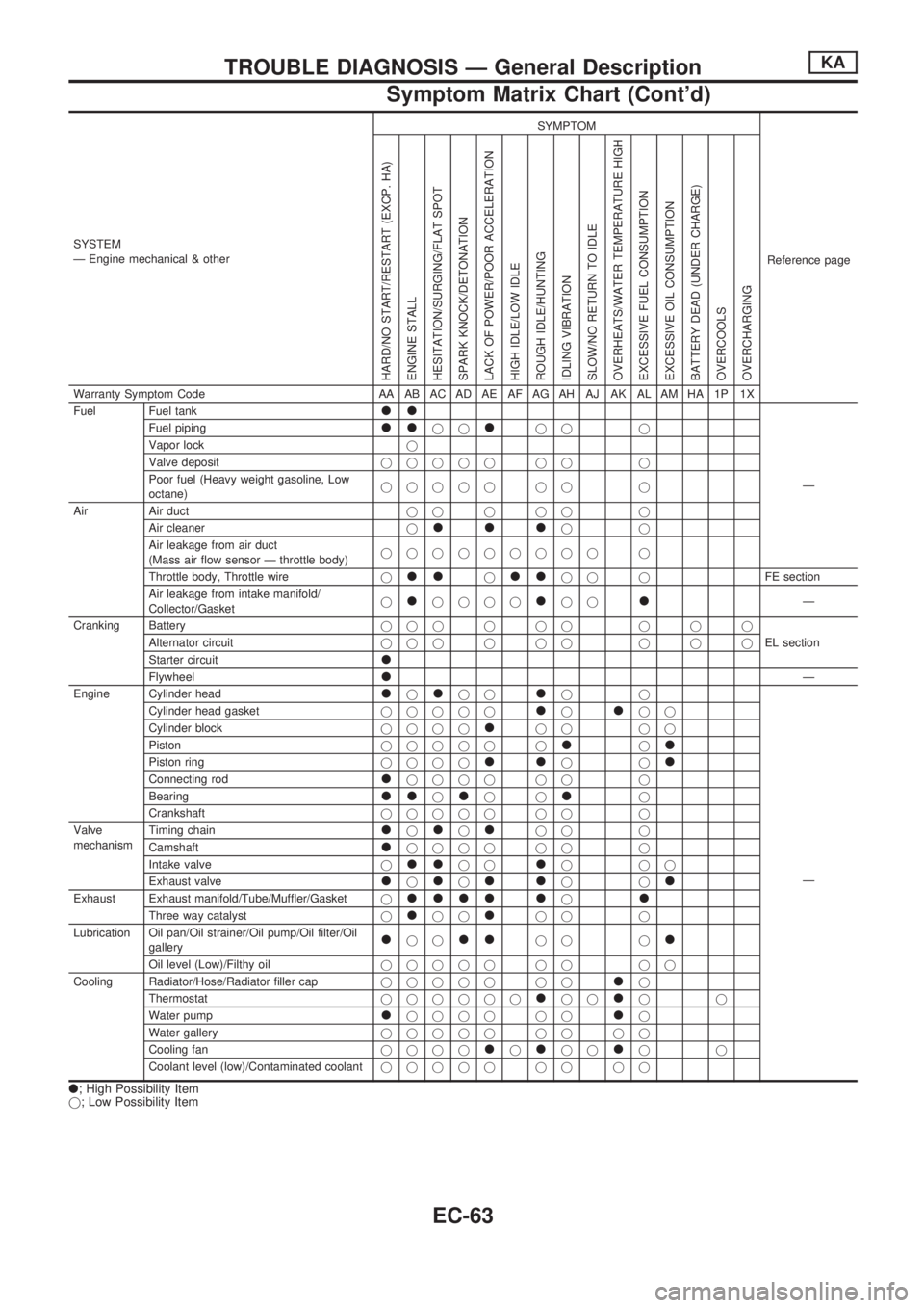
SYSTEM
Ð Engine mechanical & otherSYMPTOM
Reference page
HARD/NO START/RESTART (EXCP. HA)
ENGINE STALL
HESITATION/SURGING/FLAT SPOT
SPARK KNOCK/DETONATION
LACK OF POWER/POOR ACCELERATION
HIGH IDLE/LOW IDLE
ROUGH IDLE/HUNTING
IDLING VIBRATION
SLOW/NO RETURN TO IDLE
OVERHEATS/WATER TEMPERATURE HIGH
EXCESSIVE FUEL CONSUMPTION
EXCESSIVE OIL CONSUMPTION
BATTERY DEAD (UNDER CHARGE)
OVERCOOLS
OVERCHARGING
Warranty Symptom Code AA AB AC AD AE AF AG AH AJ AK AL AM HA 1P 1X
Fuel Fuel tank
ll
Ð Fuel piping
lljjljj j
Vapor lockj
Valve depositjjjjj jj j
Poor fuel (Heavy weight gasoline, Low
octane)jjjjj jj j
Air Air ductjjjjj j
Air cleanerj
llljj
Air leakage from air duct
(Mass air flow sensor Ð throttle body)jjjjjjjjj j
Throttle body, Throttle wirej
lljlljj jFE section
Air leakage from intake manifold/
Collector/Gasketj
ljjjjljjlÐ
Cranking Batteryjjjjjj jjj
EL section Alternator circuitjjjjjj jjj
Starter circuit
l
FlywheellÐ
Engine Cylinder head
ljljjljj
Ð Cylinder head gasketjjjjj
ljljj
Cylinder blockjjjj
ljj jj
Pistonjjjjj j
ljl
Piston ringjjjjlljjl
Connecting rodljjjj jj j
Bearing
lljljjlj
Crankshaftjjjjj jj j
Valve
mechanismTiming chain
ljljljj j
Camshaft
ljjjj jj j
Intake valvej
lljjljjj
Exhaust valve
ljljlljjl
Exhaust Exhaust manifold/Tube/Muffler/Gasketjllll ljl
Three way catalystjljjljj j
Lubrication Oil pan/Oil strainer/Oil pump/Oil filter/Oil
gallery
ljjlljj jl
Oil level (Low)/Filthy oiljjjjj jj jj
Cooling Radiator/Hose/Radiator filler capjjjjj jj
lj
Thermostatjjjjjj
ljjljj
Water pump
ljjjj jjlj
Water galleryjjjjj jj jj
Cooling fanjjjj
ljljjljj
Coolant level (low)/Contaminated coolantjjjjj jj jj
l; High Possibility Item
j; Low Possibility Item
TROUBLE DIAGNOSIS Ð General DescriptionKA
Symptom Matrix Chart (Cont'd)
EC-63
Page 258 of 1659
Overheat
ON BOARD DIAGNOSIS LOGIC
If the cooling fan or another component in the cooling system malfunctions, the engine coolant temperature
will rise.
When the engine coolant temperature reaches an abnormally high temperature condition, a malfunction is
indicated.
Diagnostic trouble
code No.Malfunction is detected when ...Check Items
(Possible Cause)
28
lEngine coolant temperature reaches an abnormally
high temperature.lCooling fan
lRadiator hose
lRadiator
lRadiator cap
lWater pump
lThermostat
For more information, refer to ``MAIN 12
CAUSES OF OVERHEATING'', EC-108.
CAUTION:
When a malfunction is indicated, be sure to replace the coolant following the procedure in MA sec-
tion (``Changing Engine Coolant'', ``ENGINE MAINTENANCE''). Also, replace the engine oil.
lFill radiator with coolant up to specified level with a filling speed of 2 liters per minute like pour-
ing coolant by kettle. Be sure to use coolant with the proper mixture ratio. Refer to MA section
(``Anti-freeze Coolant Mixture Ratio'', ``RECOMMENDED FLUIDS AND LUBRICANTS'').
lAfter refilling coolant, run engine to ensure that no water-flow noise is emitted.
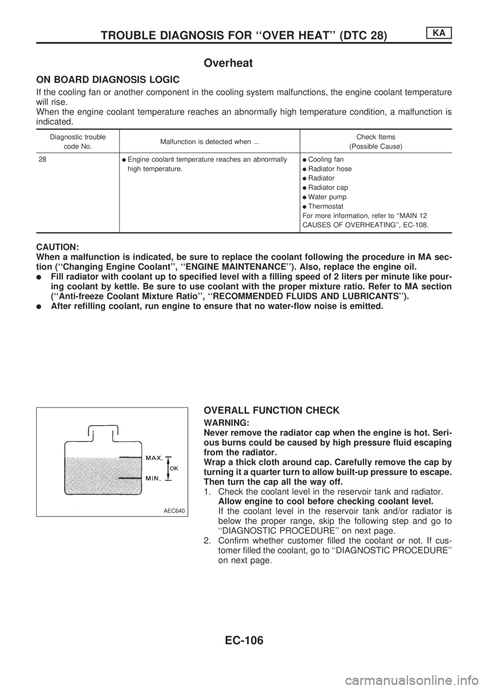
OVERALL FUNCTION CHECK
WARNING:
Never remove the radiator cap when the engine is hot. Seri-
ous burns could be caused by high pressure fluid escaping
from the radiator.
Wrap a thick cloth around cap. Carefully remove the cap by
turning it a quarter turn to allow built-up pressure to escape.
Then turn the cap all the way off.
1. Check the coolant level in the reservoir tank and radiator.
Allow engine to cool before checking coolant level.
If the coolant level in the reservoir tank and/or radiator is
below the proper range, skip the following step and go to
``DIAGNOSTIC PROCEDURE'' on next page.
2. Confirm whether customer filled the coolant or not. If cus-
tomer filled the coolant, go to ``DIAGNOSTIC PROCEDURE''
on next page.
AEC640
TROUBLE DIAGNOSIS FOR ``OVER HEAT'' (DTC 28)KA
EC-106
Page 259 of 1659
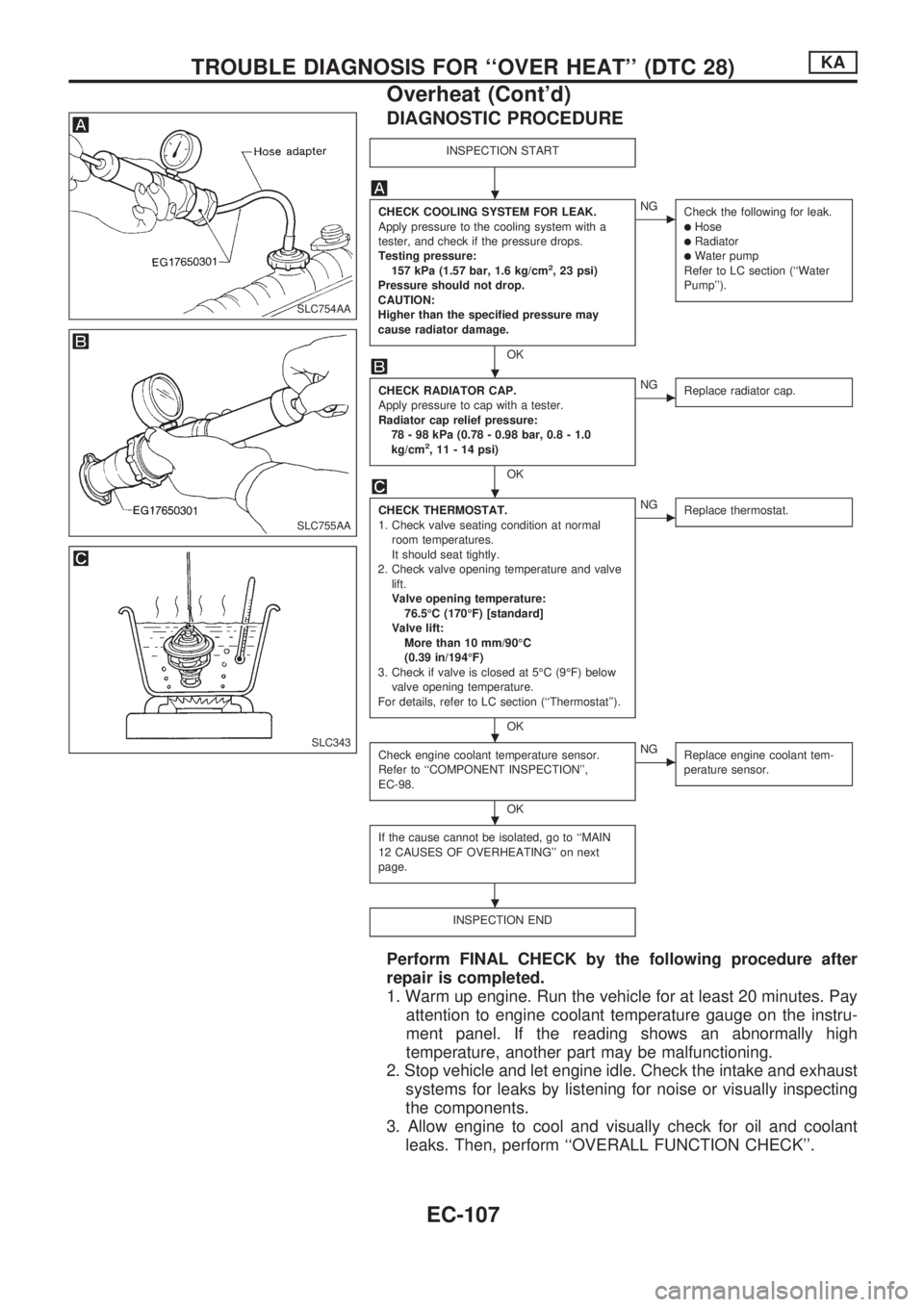
DIAGNOSTIC PROCEDURE
INSPECTION START
CHECK COOLING SYSTEM FOR LEAK.
Apply pressure to the cooling system with a
tester, and check if the pressure drops.
Testing pressure:
157 kPa (1.57 bar, 1.6 kg/cm
2, 23 psi)
Pressure should not drop.
CAUTION:
Higher than the specified pressure may
cause radiator damage.
OK
cNG
Check the following for leak.
lHoselRadiatorlWater pump
Refer to LC section (``Water
Pump'').
CHECK RADIATOR CAP.
Apply pressure to cap with a tester.
Radiator cap relief pressure:
78 - 98 kPa (0.78 - 0.98 bar, 0.8 - 1.0
kg/cm
2, 11 - 14 psi)
OK
cNG
Replace radiator cap.
CHECK THERMOSTAT.
1. Check valve seating condition at normal
room temperatures.
It should seat tightly.
2. Check valve opening temperature and valve
lift.
Valve opening temperature:
76.5ÉC (170ÉF) [standard]
Valve lift:
More than 10 mm/90ÉC
(0.39 in/194ÉF)
3. Check if valve is closed at 5ÉC (9ÉF) below
valve opening temperature.
For details, refer to LC section (``Thermostat'').
OK
cNG
Replace thermostat.
Check engine coolant temperature sensor.
Refer to ``COMPONENT INSPECTION'',
EC-98.
OK
cNG
Replace engine coolant tem-
perature sensor.
If the cause cannot be isolated, go to ``MAIN
12 CAUSES OF OVERHEATING'' on next
page.
INSPECTION END
Perform FINAL CHECK by the following procedure after
repair is completed.
1. Warm up engine. Run the vehicle for at least 20 minutes. Pay
attention to engine coolant temperature gauge on the instru-
ment panel. If the reading shows an abnormally high
temperature, another part may be malfunctioning.
2. Stop vehicle and let engine idle. Check the intake and exhaust
systems for leaks by listening for noise or visually inspecting
the components.
3. Allow engine to cool and visually check for oil and coolant
leaks. Then, perform ``OVERALL FUNCTION CHECK''.
SLC754AA
SLC755AA
SLC343
.
.
.
.
.
.
TROUBLE DIAGNOSIS FOR ``OVER HEAT'' (DTC 28)KA
Overheat (Cont'd)
EC-107
Page 260 of 1659
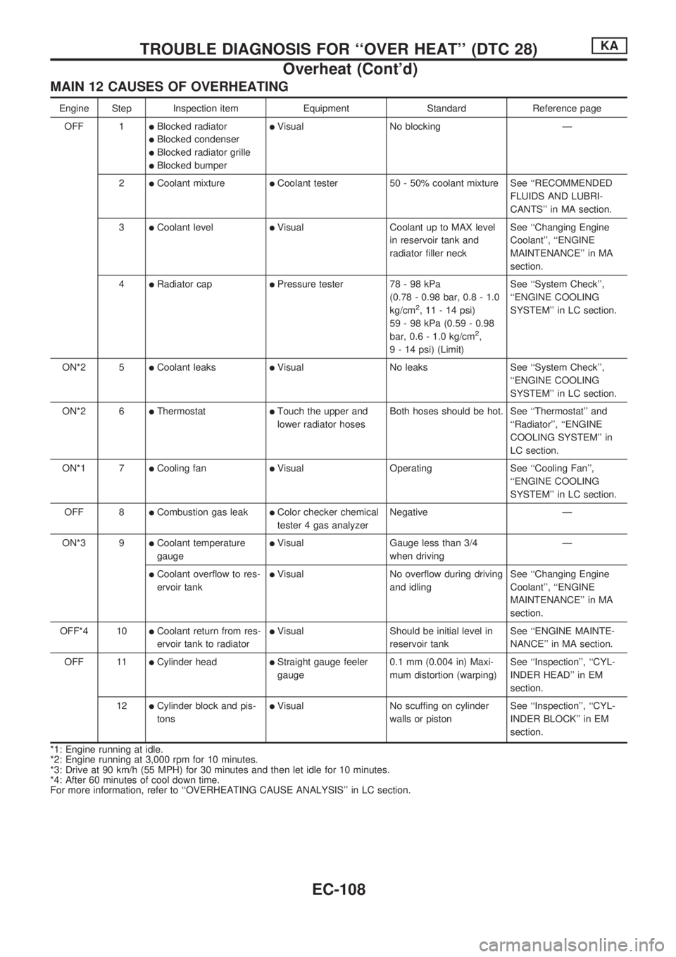
MAIN 12 CAUSES OF OVERHEATING
Engine Step Inspection item Equipment Standard Reference page
OFF 1
lBlocked radiator
lBlocked condenser
lBlocked radiator grille
lBlocked bumper
lVisual No blocking Ð
2
lCoolant mixturelCoolant tester 50 - 50% coolant mixture See ``RECOMMENDED
FLUIDS AND LUBRI-
CANTS'' in MA section.
3
lCoolant levellVisual Coolant up to MAX level
in reservoir tank and
radiator filler neckSee ``Changing Engine
Coolant'', ``ENGINE
MAINTENANCE'' in MA
section.
4
lRadiator caplPressure tester 78 - 98 kPa
(0.78 - 0.98 bar, 0.8 - 1.0
kg/cm
2, 11 - 14 psi)
59 - 98 kPa (0.59 - 0.98
bar, 0.6 - 1.0 kg/cm
2,
9 - 14 psi) (Limit)See ``System Check'',
``ENGINE COOLING
SYSTEM'' in LC section.
ON*2 5
lCoolant leakslVisual No leaks See ``System Check'',
``ENGINE COOLING
SYSTEM'' in LC section.
ON*2 6
lThermostatlTouch the upper and
lower radiator hosesBoth hoses should be hot. See ``Thermostat'' and
``Radiator'', ``ENGINE
COOLING SYSTEM'' in
LC section.
ON*1 7
lCooling fanlVisual Operating See ``Cooling Fan'',
``ENGINE COOLING
SYSTEM'' in LC section.
OFF 8
lCombustion gas leaklColor checker chemical
tester 4 gas analyzerNegative Ð
ON*3 9
lCoolant temperature
gaugelVisual Gauge less than 3/4
when drivingÐ
lCoolant overflow to res-
ervoir tanklVisual No overflow during driving
and idlingSee ``Changing Engine
Coolant'', ``ENGINE
MAINTENANCE'' in MA
section.
OFF*4 10
lCoolant return from res-
ervoir tank to radiatorlVisual Should be initial level in
reservoir tankSee ``ENGINE MAINTE-
NANCE'' in MA section.
OFF 11
lCylinder headlStraight gauge feeler
gauge0.1 mm (0.004 in) Maxi-
mum distortion (warping)See ``Inspection'', ``CYL-
INDER HEAD'' in EM
section.
12
lCylinder block and pis-
tonslVisual No scuffing on cylinder
walls or pistonSee ``Inspection'', ``CYL-
INDER BLOCK'' in EM
section.
*1: Engine running at idle.
*2: Engine running at 3,000 rpm for 10 minutes.
*3: Drive at 90 km/h (55 MPH) for 30 minutes and then let idle for 10 minutes.
*4: After 60 minutes of cool down time.
For more information, refer to ``OVERHEATING CAUSE ANALYSIS'' in LC section.
TROUBLE DIAGNOSIS FOR ``OVER HEAT'' (DTC 28)KA
Overheat (Cont'd)
EC-108
Page 699 of 1659
CAUTION:
lWhen installing sliding parts such as rocker arms, cam-
shaft and oil seal, be sure to apply new engine oil on
their sliding surfaces.
lWhen tightening cylinder head bolts and rocker shaft
bolts, apply new engine oil to thread portions and seat
surfaces of bolts.
Removal
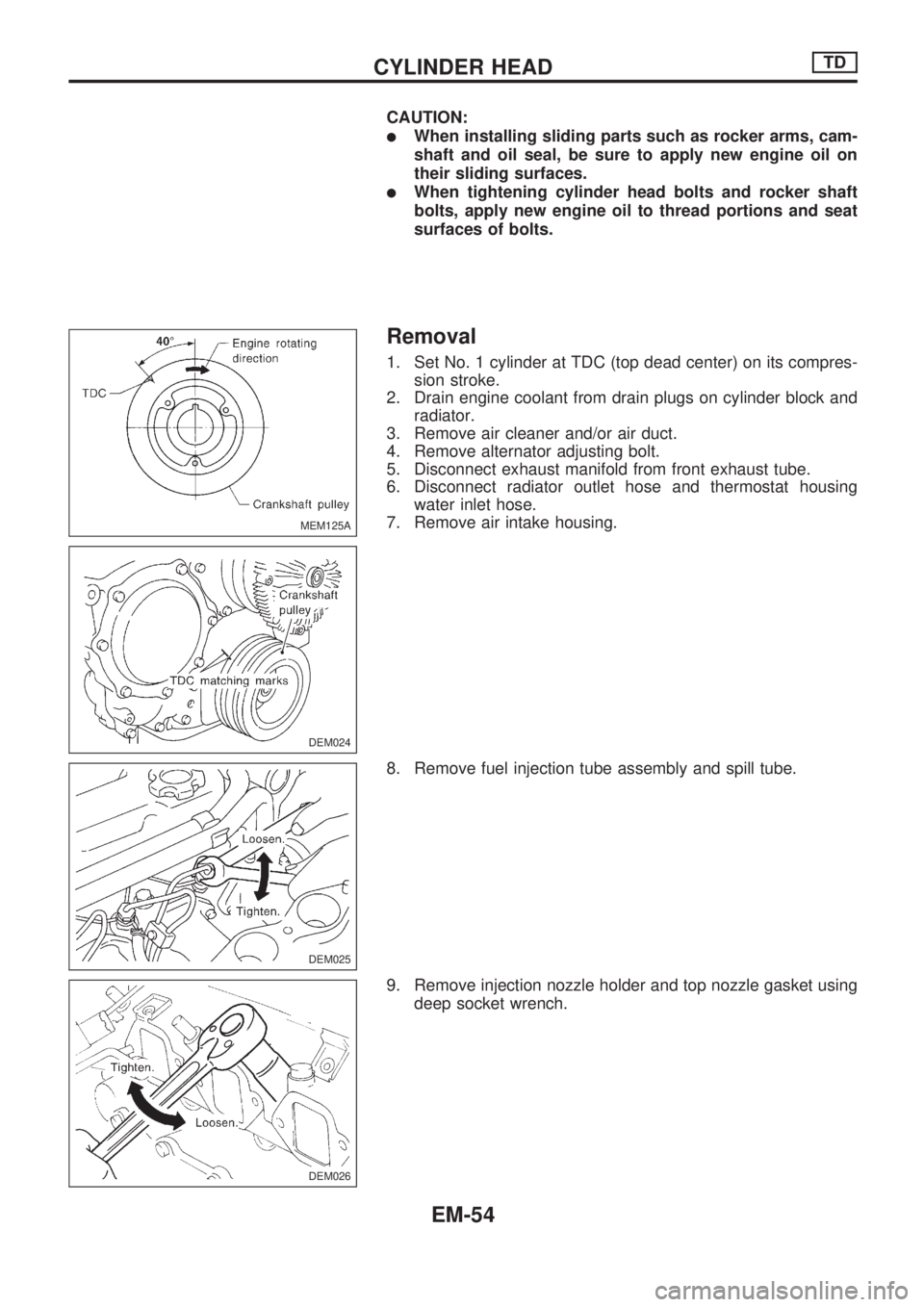
1. Set No. 1 cylinder at TDC (top dead center) on its compres-
sion stroke.
2. Drain engine coolant from drain plugs on cylinder block and
radiator.
3. Remove air cleaner and/or air duct.
4. Remove alternator adjusting bolt.
5. Disconnect exhaust manifold from front exhaust tube.
6. Disconnect radiator outlet hose and thermostat housing
water inlet hose.
7. Remove air intake housing.
8. Remove fuel injection tube assembly and spill tube.
9. Remove injection nozzle holder and top nozzle gasket using
deep socket wrench.
MEM125A
DEM024
DEM025
DEM026
CYLINDER HEADTD
EM-54
Page 700 of 1659
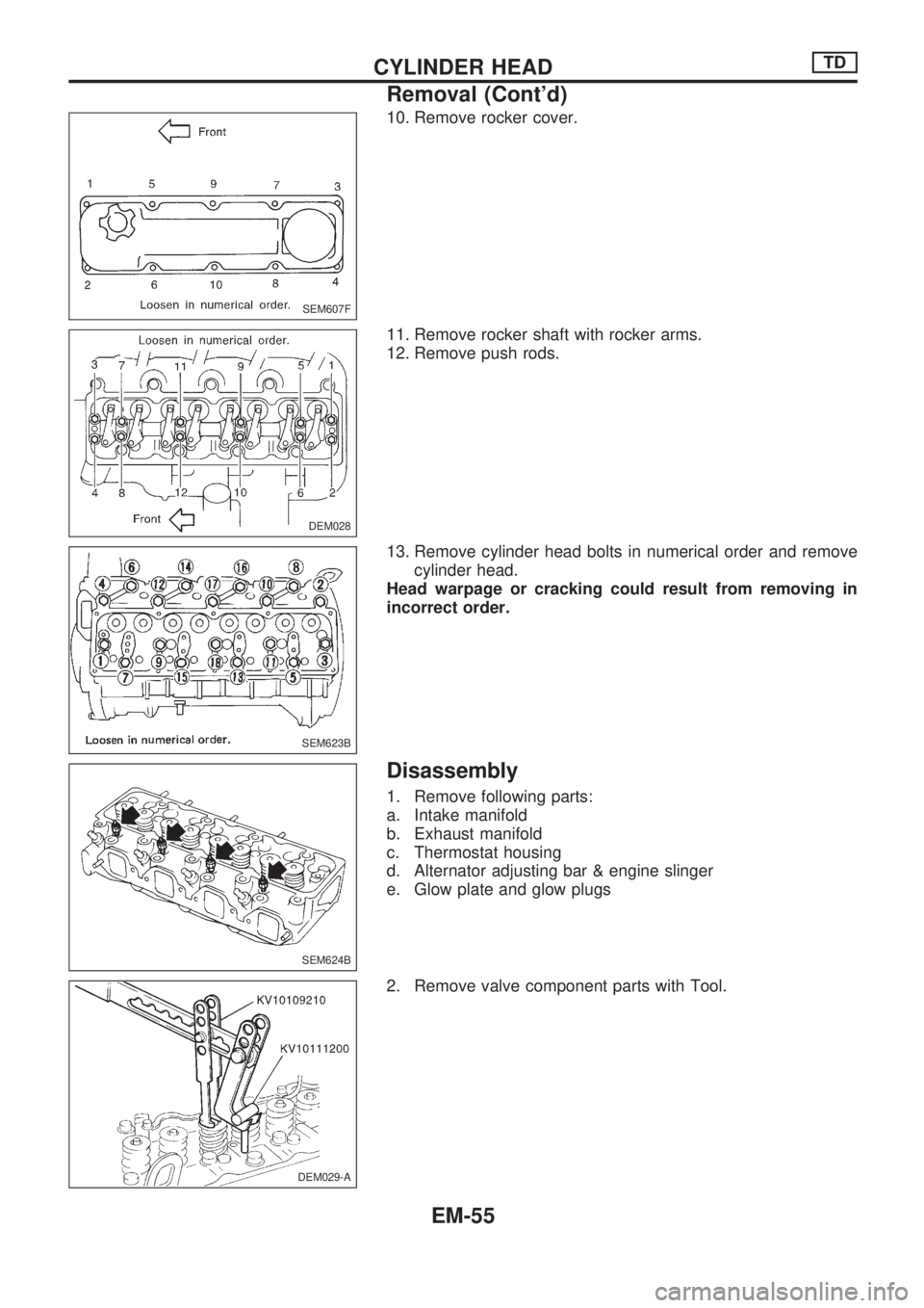
10. Remove rocker cover.
11. Remove rocker shaft with rocker arms.
12. Remove push rods.
13. Remove cylinder head bolts in numerical order and remove
cylinder head.
Head warpage or cracking could result from removing in
incorrect order.
Disassembly
1. Remove following parts:
a. Intake manifold
b. Exhaust manifold
c. Thermostat housing
d. Alternator adjusting bar & engine slinger
e. Glow plate and glow plugs
2. Remove valve component parts with Tool.
SEM607F
DEM028
SEM623B
SEM624B
DEM029-A
CYLINDER HEADTD
Removal (Cont'd)
EM-55
Page 711 of 1659
10. Connect thermostat housing water inlet hose and radiator
hose.
11. After assembling all disassembled parts, fill radiator and
engine with new coolant up to filler opening.
CYLINDER HEADTD
Installation (Cont'd)
EM-66
Page 869 of 1659
Radiator (KA24 engine) ................................. LC-9
Radiator (TD25 engine) ............................... LC-24
Rear axle ....................................................... RA-5
Rear body..................................................... BT-40
Rear case (Transfer) ...................................... TF-8
Rear combination lamp removal and
installation................................................. BT-24
Rear cover gasket replacement diff. ........... PD-13
Rear door ..................................................... BT-11
Rear drum brake.......................................... BR-26
Rear fog lamp............................................... EL-72
Rear seat belt ................................................ RS-4
Rear seat...................................................... BT-33
Rear suspension .......................................... RA-12
Rear window defogger ............................... EL-135
Refrigerant connection precaution................. HA-2
Refrigerant discharging evacuating
charging ................................................... HA-49
Refrigerant general precaution ...................... HA-2
Refrigerant lines........................................... HA-52
Refrigeration cycle ....................................... HA-12
Release bearing (clutch) ................................ CL-9
Removal and installation (Transfer) ............... TF-6
Resistor ...................................................... EC-105
Reverse idler shaft (M/T) (FS5R30A) ......... MT-36
Reverse idler shaft (M/T) (FS5W71C) ........ MT-15
Reverse lamp switch (M/T) - See
Back-up lamp switch (M/T) ........................ MT-9
Reverse main gear (M/T) (FS5R30A) ......... MT-36
Reverse main gear (M/T) (FS5W71C) ........ MT-15
Ring gear diff. inspection (C200)................. PD-38
Ring gear diff. inspection (H233B) .............. PD-60
Road wheel size ........................................... GI-46
Roof trim....................................................... BT-21
Room lamp - See Interior lamp.................... EL-85
Rotor disc (front) .......................................... FA-16
S
S/SIG - Wiring diagram...............................EC-149
SAE J1930 terminology list........................... GI-55
SMJ (super multiple junction) .................... Foldout
SRS - See Supplemental Restraint
System ....................................................... RS-6
SRS Trouble diagnoses
(2WD models) .......................................... RS-17
SRS Trouble diagnoses
(4WD models) .......................................... RS-22
START - Wiring diagram .............................. EL-26
SWL/V - Wiring diagram ............................ EC-163
Screw jack..................................................... GI-48
Seal - See Exterior....................................... BT-24
Seat belt inspection ..................................... MA-40
Seat belt, front ............................................... RS-3
Seat belt, rear ................................................ RS-4
Seat, front..................................................... BT-30
Seat, rear ..................................................... BT-33
Self-diagnostic results.................................. EC-38
Shift control (Transfer) ................................. TF-10Shift control components (M/T)
(FS5R30A) ................................................MT-38
Shift control components (M/T)
(FS5W71C) .............................................. MT-17
Shift fork (M/T) (FS5R30A) ......................... MT-38
Shift fork (M/T) (FS5W71C) ........................ MT-17
Shift lever (FS5R30A) ................................. MT-38
Shift lever (FS5W71C) ................................ MT-17
Shock absorber (front) ................................. FA-28
Shock absorber (rear).................................. RA-13
Side bearing preload (R180A) ..................... PD-23
Side bearing preload (C200) ....................... PD-45
Side trim ....................................................... BT-15
Side window ................................................. BT-38
Spark plug replacement .............................. MA-20
Spiral cable .................................................. RS-11
Spot lamp ..................................................... EL-85
Stabilizer bar (front) ..................................... FA-31
Standardized relay ......................................... EL-3
Start signal ................................................. EC-149
Starter ........................................................... EL-33
Starting system............................................. EL-26
Steering gear and linkage inspection.......... MA-37
Steering gear oil level ................................. MA-38
Steering knuckle........................................... FA-18
Steering linkage ........................................... ST-37
Steering wheel and column ........................... ST-9
Steering wheel play........................................ ST-6
Steering wheel turning force .......................... ST-6
Striking rod (M/T) (FS5R30A) ..................... MT-38
Striking rod (M/T) (FS5W71C) .................... MT-17
Sub-gear (M/T) (FS5R30A) ......................... MT-36
Sub-gear (M/T) (FS5W71C) ........................ MT-15
Sunroof ......................................................... BT-35
Supplemental Restraint System .................... RS-6
Supplemental restraint system - Wiring
diagram (2WD models) ............................ RS-18
Supplemental restraint system - Wiring
diagram (4WD models) ............................ RS-26
Swirl control valve control solenoid
valve ....................................................... EC-161
Symbols and abbreviations............................. GI-8
Synchronizer (M/T) (FS5R30A) ................... MT-36
Synchronizer (M/T) (FS5W71C) .................. MT-15
T
TAIL/L - Wiring diagram ................................EL-66
TPS - Wiring diagram ................................ EC-115
TURN - Wiring diagram................................ EL-75
Tail lamp ....................................................... EL-66
Temperature control cable and linkage
adjustment................................................ HA-47
Tension rod (front) ....................................... FA-33
Thermal protector ........................................ HA-45
Thermo control amp .................................... HA-44
Thermostat (KA24 engine) ............................. LC-8
Thermostat (TD25 engine) ........................... LC-23
Three way catalyst precautions ...................... GI-4
ALPHABETICAL INDEX
IDX-7