Page 17 of 54
Be careful to keep the side bearing outer races together with
their respective inner cones Ð do not mix them up.
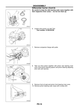
6. Loosen drive pinion nut with Tool.
Tool number: KV38104700
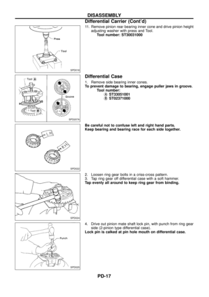
7. Remove companion ¯ange with puller.
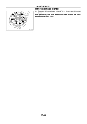
8. Take out drive pinion together with pinion rear bearing inner
cone, drive pinion bearing spacer and pinion bearing adjusting
shim with soft hammer.
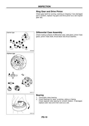
9. Remove front oil seal and pinion front bearing inner cone.
10. Remove pinion bearing outer races with a brass drift.
SPD011
SPD012
SPD686
SPD687
SPD563
DISASSEMBLY
Differential Carrier (Cont'd)
PD-16
Page 18 of 54
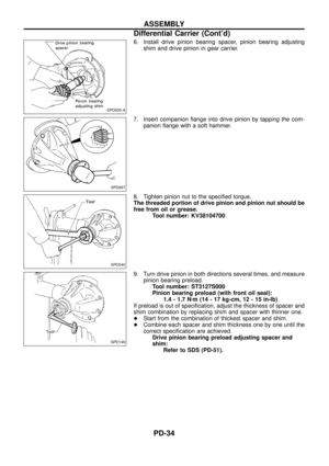
11. Remove pinion rear bearing inner cone and drive pinion height
adjusting washer with press and Tool.
Tool number: ST30031000
Differential Case
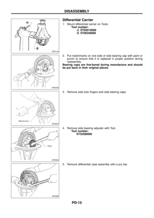
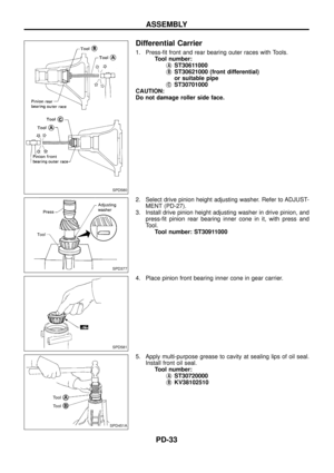
1. Remove side bearing inner cones.
To prevent damage to bearing, engage puller jaws in groove.
Tool number:
j
AST33051001
j
BST02371000
Be careful not to confuse left and right hand parts.
Keep bearing and bearing race for each side together.
2. Loosen ring gear bolts in a criss-cross pattern.
3. Tap ring gear off differential case with a soft hammer.
Tap evenly all around to keep ring gear from binding.
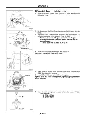
4. Drive out pinion mate shaft lock pin, with punch from ring gear
side (2-pinion type differential case).
Lock pin is calked at pin hole mouth on differential case.
SPD018
SPD207A
SPD022
SPD024
SPD025
DISASSEMBLY
Differential Carrier (Cont'd)
PD-17
Page 19 of 54
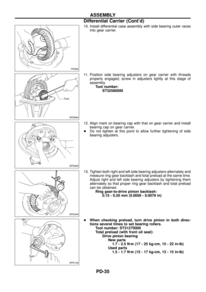
5. Separate differential case LH and RH (4-pinion type differential
case).
Put matchmarks on both differential case LH and RH sides
prior to separating them.
SPD716
DISASSEMBLY
Differential Case (Cont'd)
PD-18
Page 20 of 54
Ring Gear and Drive Pinion
Check gear teeth for scoring, cracking or chipping. If any damaged
part is evident, replace ring gear and drive pinion as a set (hypoid
gear set).
Differential Case Assembly
Check mating surfaces of differential case, side gears, pinion mate
gears, pinion mate shaft, thrust block and thrust washers.
Bearing
1. Thoroughly clean bearing.
2. Check bearings for wear, scratches, pitting or ¯aking.
Check tapered roller bearing for smooth rotation. If damaged,
replace outer race and inner cone as a set.
SPD530
SPD717
SPD715
INSPECTION
PD-19
Page 21 of 54
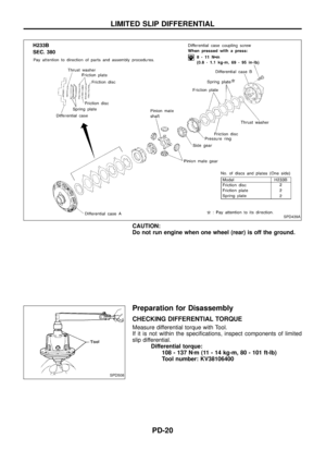
CAUTION:
Do not run engine when one wheel (rear) is off the ground.
Preparation for Disassembly
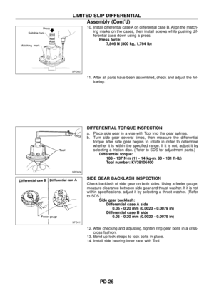
CHECKING DIFFERENTIAL TORQUE
Measure differential torque with Tool.
If it is not within the speci®cations, inspect components of limited
slip differential.
Differential torque:
108 - 137 Nzm (11 - 14 kg-m, 80 - 101 ft-lb)
Tool number: KV38106400
SPD439A
SPD508
LIMITED SLIP DIFFERENTIAL
PD-20
Page 22 of 54
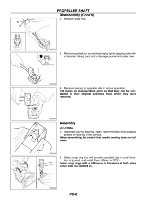
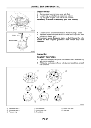
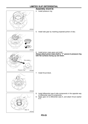
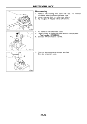
Disassembly
1. Remove side bearing inner cone with Tool.
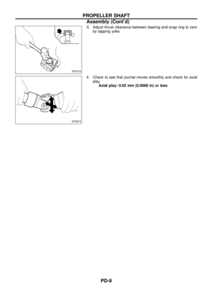
2. Loosen ring gear bolts in a criss-cross pattern.
3. Tap ring gear off gear case with a soft hammer.
Tap evenly all around to keep ring gear from binding.
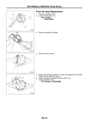
4. Loosen screws on differential cases A and B using a press.
5. Separate differential cases A and B. Draw out component parts
(discs and plates, etc.).
Put marks on gears, discs and plates so that they can be rein-
stalled in their original positions from which they were
removed.
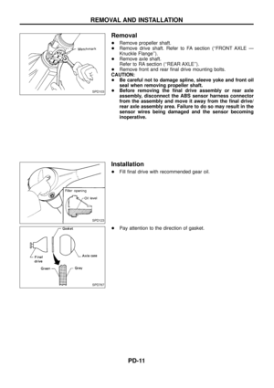
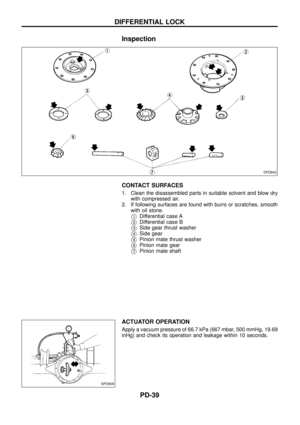
Inspection
CONTACT SURFACES
1. Clean the disassembled parts in suitable solvent and blow dry
with compressed air.
2. If following surfaces are found with burrs or scratches, smooth
with oil stone.
V1Differential case A
V2Differential case B
V3Pressure ring
V4Thrust washer
V5Pinion mate shaft
V6Thrust block
V7Pinion mate gear
V8Side gear
SPD476
SPD507
SPD503
LIMITED SLIP DIFFERENTIAL
PD-21
Page 23 of 54
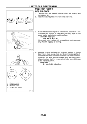
DISC AND PLATE
1. Clean the discs and plates in suitable solvent and blow dry with
compressed air.
2. Inspect discs and plates for wear, nicks and burrs.
3. To test if friction disc or plate is not distorted, place it on a sur-
face plate and rotate it by hand with indicating ®nger of dial
gauge resting against disc or plate surface.
Allowable warpage:
0.08 mm (0.0031 in)
If it exceeds limits, replace with a new plate to eliminate possi-
bility of clutch slippage or sticking.
4. Measure frictional surfaces and projected portions of friction
disc, friction plate, spring plate, and determine each part's dif-
ferences to see if the speci®ed wear limit has been exceeded.
If any part has worn beyond the wear limit, and deformed or
fatigued, replace it with a new one that is the same thickness
as the projected portion.
Wear limit:
0.1 mm (0.004 in) or less
SPD478
SPD279
SPD403
LIMITED SLIP DIFFERENTIAL
Inspection (Cont'd)
PD-22
Page 24 of 54

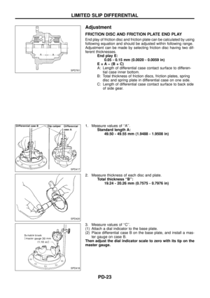
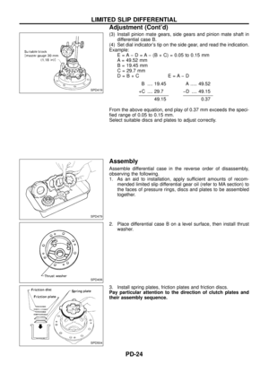
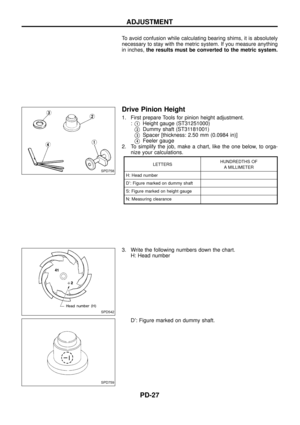
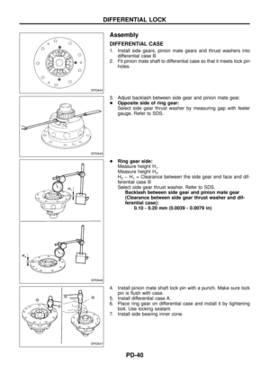
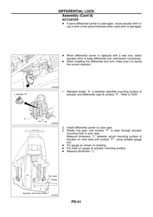
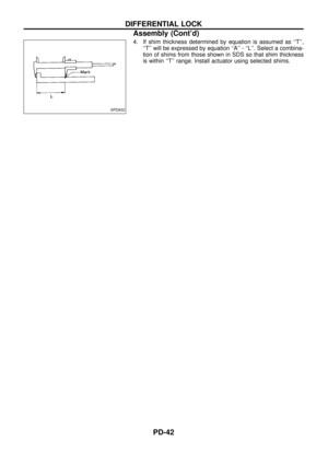
Adjustment
FRICTION DISC AND FRICTION PLATE END PLAY
End play of friction disc and friction plate can be calculated by using
following equation and should be adjusted within following range.
Adjustment can be made by selecting friction disc having two dif-
ferent thicknesses.
End play E:
0.05 - 0.15 mm (0.0020 - 0.0059 in)
E=Aþ(B+C)
A: Length of differential case contact surface to differen-
tial case inner bottom.
B: Total thickness of friction discs, friction plates, spring
disc and spring plate in differential case on one side.
C: Length of differential case contact surface to back side
of side gear.
1. Measure values of ``A''.
Standard length A:
49.50 - 49.55 mm (1.9488 - 1.9508 in)
2. Measure thickness of each disc and plate.
Total thickness ``B'':
19.24 - 20.26 mm (0.7575 - 0.7976 in)
3. Measure values of ``C''.
(1) Attach a dial indicator to the base plate.
(2) Place differential case B on the base plate, and install a mas-
ter gauge on case B.
Then adjust the dial indicator scale to zero with its tip on the
master gauge.
SPD761
SPD417
SPD420
SPD418
LIMITED SLIP DIFFERENTIAL
PD-23


.
Put matchmarks on both differential case LH and RH sides
prior to separating them.
SPD716
DISASSEMBLY
Differential Case (Cont")
.
Differential Case Assembly")
 is off the ground.
Preparation for Disassembly
CHECKING DIFFERENTIAL TORQUE
Measure differential torque with Tool.
If it is not within the speci®catio")

