1998 NISSAN PATROL Front bearing
[x] Cancel search: Front bearingPage 1 of 54
PROPELLER SHAFT &
DIFFERENTIAL CARRIER
SECTION
PD
CONTENTS
PREPARATION................................................................1
Special Service Tools ..................................................1
NOISE, VIBRATION AND HARSHNESS (NVH)
TROUBLESHOOTING.....................................................4
NVH Troubleshooting Chart.........................................4
PROPELLER SHAFT......................................................5
Front Propeller Shaft ...................................................5
Rear Propeller Shaft ....................................................5
On-vehicle Service.......................................................6
Removal and Installation .............................................7
Inspection.....................................................................7
Disassembly.................................................................7
Assembly .....................................................................8
ON-VEHICLE SERVICE (Final Drive)..........................10
Front Oil Seal Replacement ......................................10
REMOVAL AND INSTALLATION.................................. 11
Removal ..................................................................... 11
Installation .................................................................. 11
FRONT FINAL DRIVE...................................................12
REAR FINAL DRIVE.....................................................13
DISASSEMBLY..............................................................14
Pre-inspection ............................................................14
Differential Carrier......................................................15
Differential Case ........................................................17
INSPECTION..................................................................19
Ring Gear and Drive Pinion ......................................19
Differential Case Assembly........................................19Bearing.......................................................................19
LIMITED SLIP DIFFERENTIAL.....................................20
Preparation for Disassembly .....................................20
Disassembly...............................................................21
Inspection...................................................................21
Adjustment .................................................................23
Assembly ...................................................................24
ADJUSTMENT...............................................................27
Drive Pinion Height ....................................................27
Tooth Contact.............................................................29
ASSEMBLY....................................................................31
Differential Case Ð 4-pinion type Ð.........................31
Differential Case Ð 2-pinion type Ð.........................32
Differential Carrier......................................................33
DIFFERENTIAL LOCK..................................................37
Actuator and Fork ......................................................37
Disassembly...............................................................38
Inspection...................................................................39
Assembly ...................................................................40
System Description ....................................................43
Component Parts Location ........................................44
Wiring Diagram Ð DIFF/L Ð/LHD Models ...............45
Wiring Diagram Ð DIFF/L Ð/RHD Models ...............47
Electrical Components Inspection .............................49
SERVICE DATA AND SPECIFICATIONS (SDS)..........51
Propeller Shaft ...........................................................51
Final Drive..................................................................52
PD
Page 2 of 54
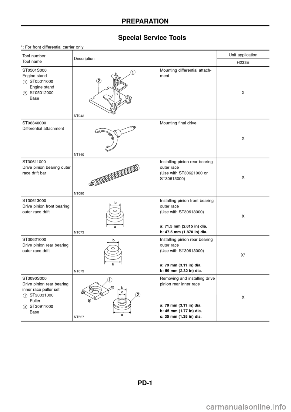
Special Service Tools
*: For front differential carrier only
Tool number
Tool nameDescriptionUnit application
H233B
ST0501S000
Engine stand
V1ST05011000
Engine stand
V2ST05012000
Base
NT042
Mounting differential attach-
ment
X
ST06340000
Differential attachment
NT140
Mounting ®nal drive
X
ST30611000
Drive pinion bearing outer
race drift bar
NT090
Installing pinion rear bearing
outer race
(Use with ST30621000 or
ST30613000)X
ST30613000
Drive pinion front bearing
outer race drift
NT073
Installing pinion front bearing
outer race
(Use with ST30613000)
X
a: 71.5 mm (2.815 in) dia.
b: 47.5 mm (1.870 in) dia.
ST30621000
Drive pinion rear bearing
outer race drift
NT073
Installing pinion rear bearing
outer race
(Use with ST30613000)
X*
a: 79 mm (3.11 in) dia.
b: 59 mm (2.32 in) dia.
ST3090S000
Drive pinion rear bearing
inner race puller set
V1ST30031000
Puller
V2ST30911000
Base
NT527
Removing and installing drive
pinion rear inner race
X
a: 79 mm (3.11 in) dia.
b: 45 mm (1.77 in) dia.
c: 35 mm (1.38 in) dia.
PREPARATION
PD-1
Page 4 of 54
Tool number
Tool nameDescriptionUnit application
H233B
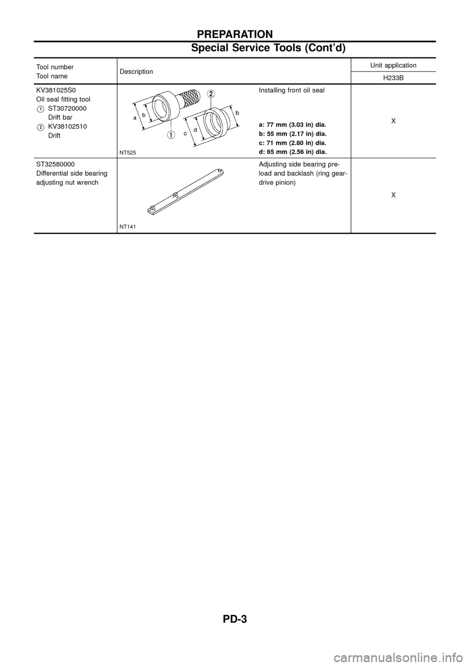
KV381025S0
Oil seal ®tting tool
V1ST30720000
Drift bar
V2KV38102510
Drift
NT525
Installing front oil seal
X
a: 77 mm (3.03 in) dia.
b: 55 mm (2.17 in) dia.
c: 71 mm (2.80 in) dia.
d: 65 mm (2.56 in) dia.
ST32580000
Differential side bearing
adjusting nut wrench
NT141
Adjusting side bearing pre-
load and backlash (ring gear-
drive pinion)
X
PREPARATION
Special Service Tools (Cont'd)
PD-3
Page 15 of 54
Pre-inspection
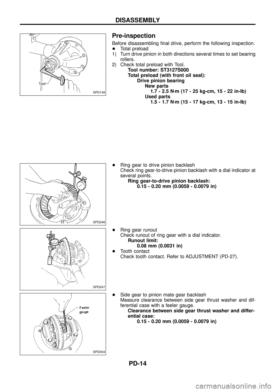
Before disassembling ®nal drive, perform the following inspection.
+Total preload
1) Turn drive pinion in both directions several times to set bearing
rollers.
2) Check total preload with Tool.
Tool number: ST3127S000
Total preload (with front oil seal):
Drive pinion bearing
New parts
1.7 - 2.5 Nzm (17 - 25 kg-cm, 15 - 22 in-lb)
Used parts
1.5 - 1.7 Nzm (15 - 17 kg-cm, 13 - 15 in-lb)
+Ring gear to drive pinion backlash
Check ring gear-to-drive pinion backlash with a dial indicator at
several points.
Ring gear-to-drive pinion backlash:
0.15 - 0.20 mm (0.0059 - 0.0079 in)
+Ring gear runout
Check runout of ring gear with a dial indicator.
Runout limit:
0.08 mm (0.0031 in)
+Tooth contact
Check tooth contact. Refer to ADJUSTMENT (PD-27).
+Side gear to pinion mate gear backlash
Measure clearance between side gear thrust washer and dif-
ferential case with a feeler gauge.
Clearance between side gear thrust washer and differ-
ential case:
0.15 - 0.20 mm (0.0059 - 0.0079 in)
SPD149
SPD246
SPD247
SPD004
DISASSEMBLY
PD-14
Page 17 of 54
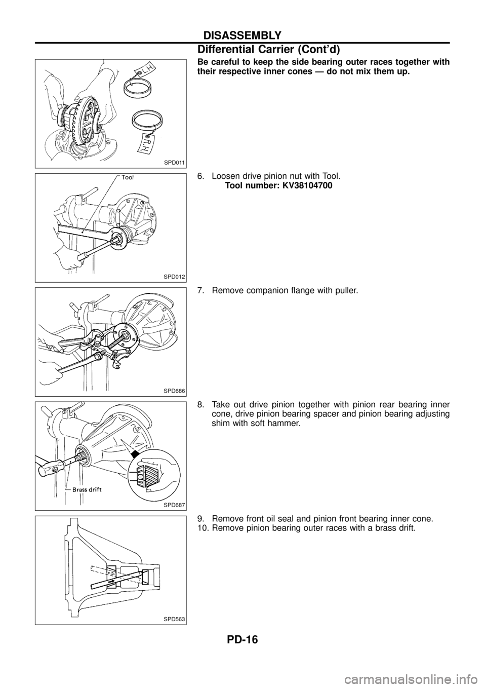
Be careful to keep the side bearing outer races together with
their respective inner cones Ð do not mix them up.
6. Loosen drive pinion nut with Tool.
Tool number: KV38104700
7. Remove companion ¯ange with puller.
8. Take out drive pinion together with pinion rear bearing inner
cone, drive pinion bearing spacer and pinion bearing adjusting
shim with soft hammer.
9. Remove front oil seal and pinion front bearing inner cone.
10. Remove pinion bearing outer races with a brass drift.
SPD011
SPD012
SPD686
SPD687
SPD563
DISASSEMBLY
Differential Carrier (Cont'd)
PD-16
Page 34 of 54
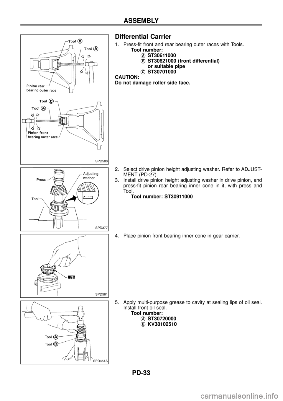
Differential Carrier
1. Press-®t front and rear bearing outer races with Tools.
Tool number:
j
AST30611000
j
BST30621000 (front differential)
or suitable pipe
j
CST30701000
CAUTION:
Do not damage roller side face.
2. Select drive pinion height adjusting washer. Refer to ADJUST-
MENT (PD-27).
3. Install drive pinion height adjusting washer in drive pinion, and
press-®t pinion rear bearing inner cone in it, with press and
Tool.
Tool number: ST30911000
4. Place pinion front bearing inner cone in gear carrier.
5. Apply multi-purpose grease to cavity at sealing lips of oil seal.
Install front oil seal.
Tool number:
j
AST30720000
j
BKV38102510
SPD580
SPD377
SPD581
SPD451A
ASSEMBLY
PD-33
Page 35 of 54
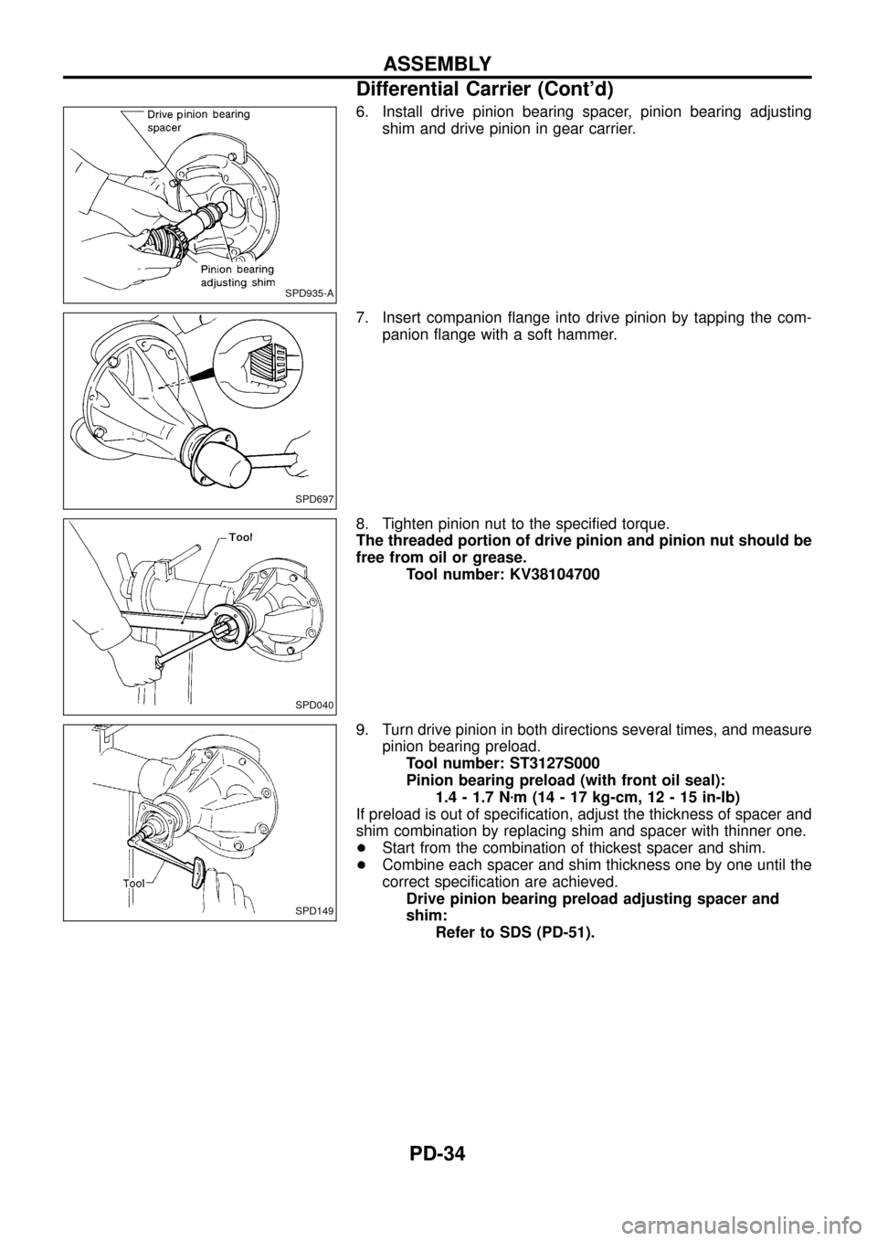
6. Install drive pinion bearing spacer, pinion bearing adjusting
shim and drive pinion in gear carrier.
7. Insert companion ¯ange into drive pinion by tapping the com-
panion ¯ange with a soft hammer.
8. Tighten pinion nut to the speci®ed torque.
The threaded portion of drive pinion and pinion nut should be
free from oil or grease.
Tool number: KV38104700
9. Turn drive pinion in both directions several times, and measure
pinion bearing preload.
Tool number: ST3127S000
Pinion bearing preload (with front oil seal):
1.4 - 1.7 Nzm (14 - 17 kg-cm, 12 - 15 in-lb)
If preload is out of speci®cation, adjust the thickness of spacer and
shim combination by replacing shim and spacer with thinner one.
+Start from the combination of thickest spacer and shim.
+Combine each spacer and shim thickness one by one until the
correct speci®cation are achieved.
Drive pinion bearing preload adjusting spacer and
shim:
Refer to SDS (PD-51).
SPD935-A
SPD697
SPD040
SPD149
ASSEMBLY
Differential Carrier (Cont'd)
PD-34
Page 36 of 54
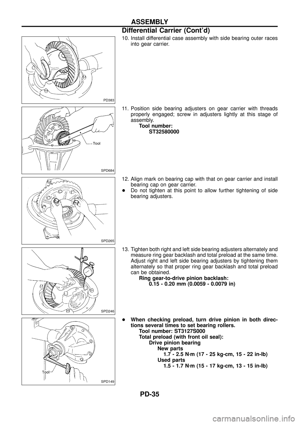
10. Install differential case assembly with side bearing outer races
into gear carrier.
11. Position side bearing adjusters on gear carrier with threads
properly engaged; screw in adjusters lightly at this stage of
assembly.
Tool number:
ST32580000
12. Align mark on bearing cap with that on gear carrier and install
bearing cap on gear carrier.
+Do not tighten at this point to allow further tightening of side
bearing adjusters.
13. Tighten both right and left side bearing adjusters alternately and
measure ring gear backlash and total preload at the same time.
Adjust right and left side bearing adjusters by tightening them
alternately so that proper ring gear backlash and total preload
can be obtained.
Ring gear-to-drive pinion backlash:
0.15 - 0.20 mm (0.0059 - 0.0079 in)
+When checking preload, turn drive pinion in both direc-
tions several times to set bearing rollers.
Tool number: ST3127S000
Total preload (with front oil seal):
Drive pinion bearing
New parts
1.7 - 2.5 Nzm (17 - 25 kg-cm, 15 - 22 in-lb)
Used parts
1.5 - 1.7 Nzm (15 - 17 kg-cm, 13 - 15 in-lb)
PD383
SPD684
SPD265
SPD246
SPD149
ASSEMBLY
Differential Carrier (Cont'd)
PD-35