Page 1 of 54

PROPELLER SHAFT &
DIFFERENTIAL CARRIER
SECTION
PD
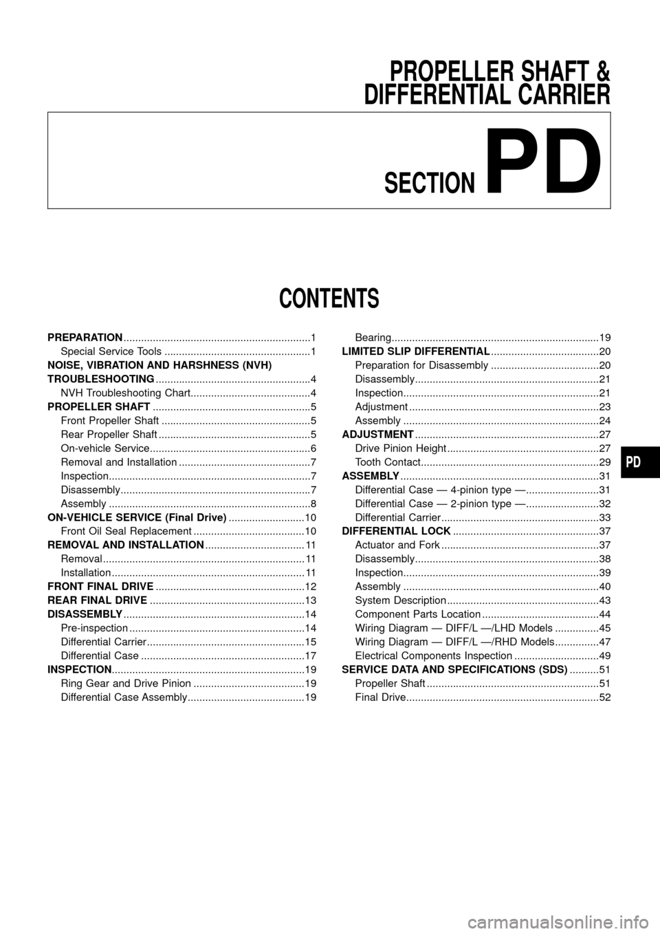
CONTENTS
PREPARATION................................................................1
Special Service Tools ..................................................1
NOISE, VIBRATION AND HARSHNESS (NVH)
TROUBLESHOOTING.....................................................4
NVH Troubleshooting Chart.........................................4
PROPELLER SHAFT......................................................5
Front Propeller Shaft ...................................................5
Rear Propeller Shaft ....................................................5
On-vehicle Service.......................................................6
Removal and Installation .............................................7
Inspection.....................................................................7
Disassembly.................................................................7
Assembly .....................................................................8
ON-VEHICLE SERVICE (Final Drive)..........................10
Front Oil Seal Replacement ......................................10
REMOVAL AND INSTALLATION.................................. 11
Removal ..................................................................... 11
Installation .................................................................. 11
FRONT FINAL DRIVE...................................................12
REAR FINAL DRIVE.....................................................13
DISASSEMBLY..............................................................14
Pre-inspection ............................................................14
Differential Carrier......................................................15
Differential Case ........................................................17
INSPECTION..................................................................19
Ring Gear and Drive Pinion ......................................19
Differential Case Assembly........................................19Bearing.......................................................................19
LIMITED SLIP DIFFERENTIAL.....................................20
Preparation for Disassembly .....................................20
Disassembly...............................................................21
Inspection...................................................................21
Adjustment .................................................................23
Assembly ...................................................................24
ADJUSTMENT...............................................................27
Drive Pinion Height ....................................................27
Tooth Contact.............................................................29
ASSEMBLY....................................................................31
Differential Case Ð 4-pinion type Ð.........................31
Differential Case Ð 2-pinion type Ð.........................32
Differential Carrier......................................................33
DIFFERENTIAL LOCK..................................................37
Actuator and Fork ......................................................37
Disassembly...............................................................38
Inspection...................................................................39
Assembly ...................................................................40
System Description ....................................................43
Component Parts Location ........................................44
Wiring Diagram Ð DIFF/L Ð/LHD Models ...............45
Wiring Diagram Ð DIFF/L Ð/RHD Models ...............47
Electrical Components Inspection .............................49
SERVICE DATA AND SPECIFICATIONS (SDS)..........51
Propeller Shaft ...........................................................51
Final Drive..................................................................52
PD
Page 2 of 54

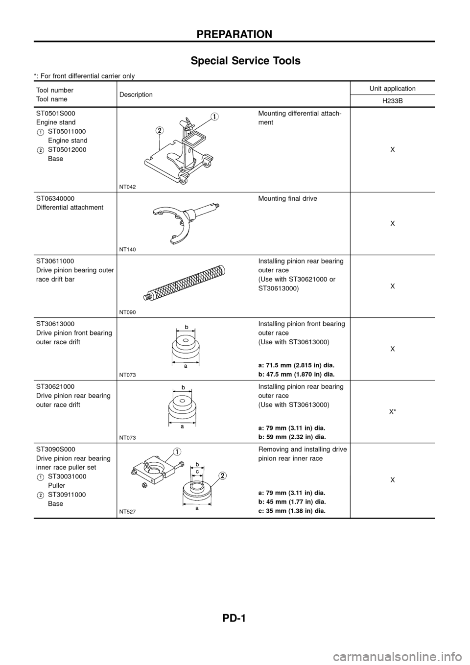
Special Service Tools
*: For front differential carrier only
Tool number
Tool nameDescriptionUnit application
H233B
ST0501S000
Engine stand
V1ST05011000
Engine stand
V2ST05012000
Base
NT042
Mounting differential attach-
ment
X
ST06340000
Differential attachment
NT140
Mounting ®nal drive
X
ST30611000
Drive pinion bearing outer
race drift bar
NT090
Installing pinion rear bearing
outer race
(Use with ST30621000 or
ST30613000)X
ST30613000
Drive pinion front bearing
outer race drift
NT073
Installing pinion front bearing
outer race
(Use with ST30613000)
X
a: 71.5 mm (2.815 in) dia.
b: 47.5 mm (1.870 in) dia.
ST30621000
Drive pinion rear bearing
outer race drift
NT073
Installing pinion rear bearing
outer race
(Use with ST30613000)
X*
a: 79 mm (3.11 in) dia.
b: 59 mm (2.32 in) dia.
ST3090S000
Drive pinion rear bearing
inner race puller set
V1ST30031000
Puller
V2ST30911000
Base
NT527
Removing and installing drive
pinion rear inner race
X
a: 79 mm (3.11 in) dia.
b: 45 mm (1.77 in) dia.
c: 35 mm (1.38 in) dia.
PREPARATION
PD-1
Page 4 of 54
Tool number
Tool nameDescriptionUnit application
H233B
KV381025S0
Oil seal ®tting tool
V1ST30720000
Drift bar
V2KV38102510
Drift
NT525
Installing front oil seal
X
a: 77 mm (3.03 in) dia.
b: 55 mm (2.17 in) dia.
c: 71 mm (2.80 in) dia.
d: 65 mm (2.56 in) dia.
ST32580000
Differential side bearing
adjusting nut wrench
NT141
Adjusting side bearing pre-
load and backlash (ring gear-
drive pinion)
X
PREPARATION
Special Service Tools (Cont'd)
PD-3
Page 6 of 54
Front Propeller Shaft
Rear Propeller Shaft
SPD434A
SPD457A
PROPELLER SHAFT
PD-5
Page 7 of 54
On-vehicle Service
PROPELLER SHAFT VIBRATION
If vibration is present at high speed, inspect propeller shaft runout
®rst.
1. Raise front and rear wheels.
2. Measure propeller shaft runout at several points by rotating
®nal drive companion ¯ange with hands.
Runout limit: 0.6 mm (0.024 in)
3. If runout exceeds speci®cations, disconnect propeller shaft at
®nal drive companion ¯ange; then rotate companion ¯ange 180
degrees and reconnect propeller shaft.
4. Check runout again. If runout still exceeds speci®cations,
replace propeller shaft assembly.
5. Perform road tests.
APPEARANCE CHECKING
+Inspect propeller shaft tube surface for dents or cracks. If
damaged, replace propeller shaft assembly.
SPD458A
SPD728
SPD102
PROPELLER SHAFT
PD-6
Page 11 of 54
Front Oil Seal Replacement
1. Remove propeller shaft.
2. Loosen drive pinion nut.
Tool number:
KV40104000
3. Remove companion ¯ange.
4. Remove front oil seal.
5. Apply multi-purpose grease to cavity at sealing lips of oil seal.
Press front oil seal into carrier.
6. Install companion ¯ange and drive pinion nut.
7. Install propeller shaft.
Tool number: KV381025S0
PD237
SPD737
SPD738
SPD739
ON-VEHICLE SERVICE (Final Drive)
PD-10
Page 12 of 54
Removal
+Remove propeller shaft.
+Remove drive shaft. Refer to FA section (``FRONT AXLE Ð
Knuckle Flange'').
+Remove axle shaft.
Refer to RA section (``REAR AXLE'').
+Remove front and rear ®nal drive mounting bolts.
CAUTION:
+Be careful not to damage spline, sleeve yoke and front oil
seal when removing propeller shaft.
+Before removing the ®nal drive assembly or rear axle
assembly, disconnect the ABS sensor harness connector
from the assembly and move it away from the ®nal drive/
rear axle assembly area. Failure to do so may result in the
sensor wires being damaged and the sensor becoming
inoperative.
Installation
+Fill ®nal drive with recommended gear oil.
+Pay attention to the direction of gasket.
SPD103
SPD123
SPD767
REMOVAL AND INSTALLATION
PD-11
Page 13 of 54
SPD436A
FRONT FINAL DRIVE
PD-12