Page 22 of 54
Disassembly
1. Remove side bearing inner cone with Tool.
2. Loosen ring gear bolts in a criss-cross pattern.
3. Tap ring gear off gear case with a soft hammer.
Tap evenly all around to keep ring gear from binding.
4. Loosen screws on differential cases A and B using a press.
5. Separate differential cases A and B. Draw out component parts
(discs and plates, etc.).
Put marks on gears, discs and plates so that they can be rein-
stalled in their original positions from which they were
removed.
Inspection
CONTACT SURFACES
1. Clean the disassembled parts in suitable solvent and blow dry
with compressed air.
2. If following surfaces are found with burrs or scratches, smooth
with oil stone.
V1Differential case A
V2Differential case B
V3Pressure ring
V4Thrust washer
V5Pinion mate shaft
V6Thrust block
V7Pinion mate gear
V8Side gear
SPD476
SPD507
SPD503
LIMITED SLIP DIFFERENTIAL
PD-21
Page 25 of 54

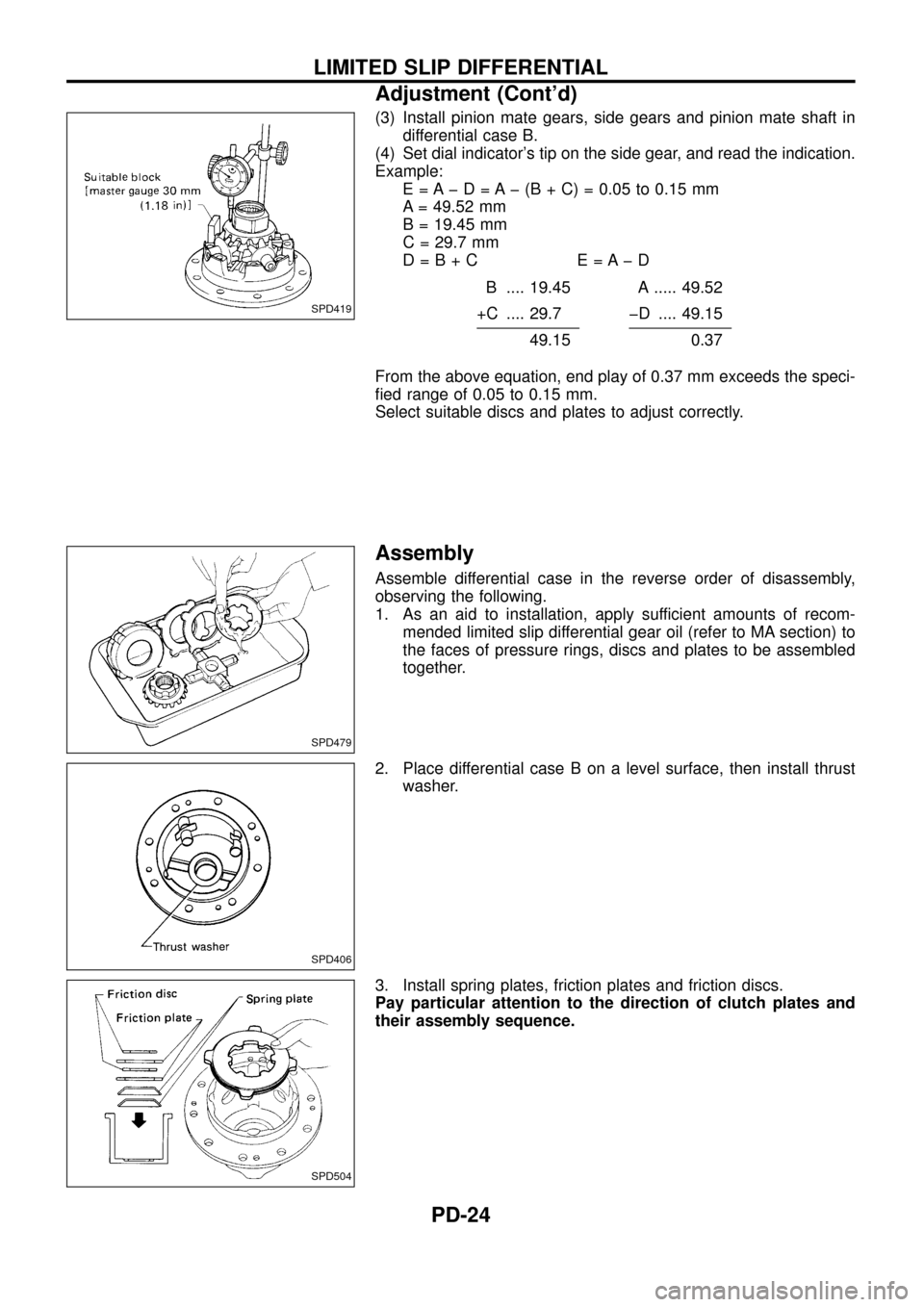
(3) Install pinion mate gears, side gears and pinion mate shaft in
differential case B.
(4) Set dial indicator's tip on the side gear, and read the indication.
Example:
E = A þ D = A þ (B + C) = 0.05 to 0.15 mm
A = 49.52 mm
B = 19.45 mm
C = 29.7 mm
D=B+C E=AþD
B .... 19.45 A ..... 49.52
+C .... 29.7 þD .... 49.15
49.150.37
From the above equation, end play of 0.37 mm exceeds the speci-
®ed range of 0.05 to 0.15 mm.
Select suitable discs and plates to adjust correctly.
Assembly
Assemble differential case in the reverse order of disassembly,
observing the following.
1. As an aid to installation, apply sufficient amounts of recom-
mended limited slip differential gear oil (refer to MA section) to
the faces of pressure rings, discs and plates to be assembled
together.
2. Place differential case B on a level surface, then install thrust
washer.
3. Install spring plates, friction plates and friction discs.
Pay particular attention to the direction of clutch plates and
their assembly sequence.
SPD419
SPD479
SPD406
SPD504
LIMITED SLIP DIFFERENTIAL
Adjustment (Cont'd)
PD-24
Page 40 of 54
Inspection
CONTACT SURFACES
1. Clean the disassembled parts in suitable solvent and blow dry
with compressed air.
2. If following surfaces are found with burrs or scratches, smooth
with oil stone.
V1Differential case A
V2Differential case B
V3Side gear thrust washer
V4Side gear
V5Pinion mate thrust washer
V6Pinion mate gear
V7Pinion mate shaft
ACTUATOR OPERATION
Apply a vacuum pressure of 66.7 kPa (667 mbar, 500 mmHg, 19.69
inHg) and check its operation and leakage within 10 seconds.
SPD842
SPD906
DIFFERENTIAL LOCK
PD-39