Page 1 of 54

PROPELLER SHAFT &
DIFFERENTIAL CARRIER
SECTION
PD
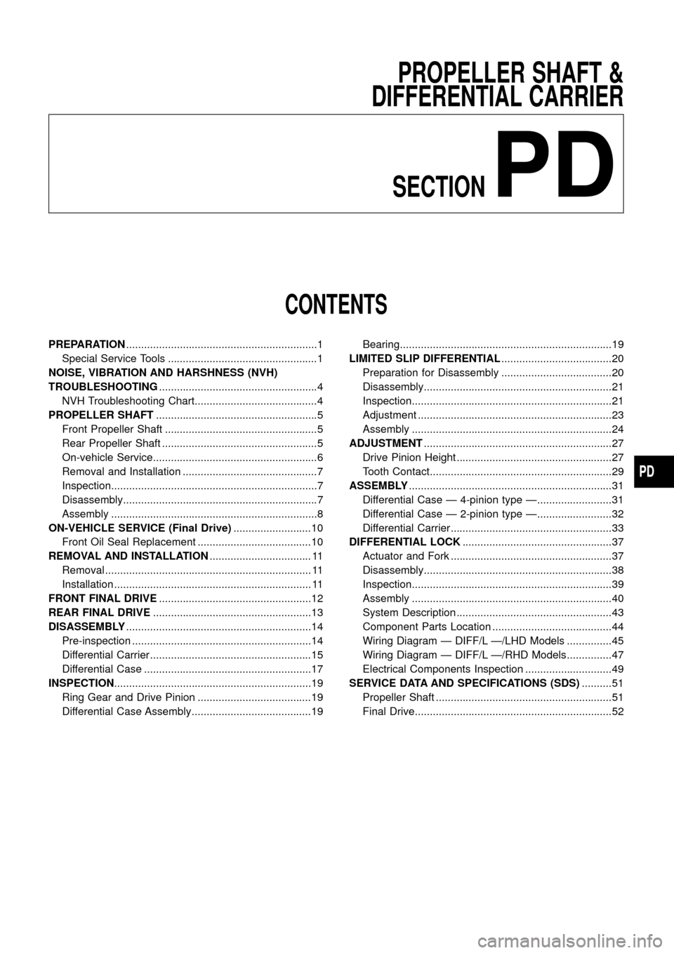
CONTENTS
PREPARATION................................................................1
Special Service Tools ..................................................1
NOISE, VIBRATION AND HARSHNESS (NVH)
TROUBLESHOOTING.....................................................4
NVH Troubleshooting Chart.........................................4
PROPELLER SHAFT......................................................5
Front Propeller Shaft ...................................................5
Rear Propeller Shaft ....................................................5
On-vehicle Service.......................................................6
Removal and Installation .............................................7
Inspection.....................................................................7
Disassembly.................................................................7
Assembly .....................................................................8
ON-VEHICLE SERVICE (Final Drive)..........................10
Front Oil Seal Replacement ......................................10
REMOVAL AND INSTALLATION.................................. 11
Removal ..................................................................... 11
Installation .................................................................. 11
FRONT FINAL DRIVE...................................................12
REAR FINAL DRIVE.....................................................13
DISASSEMBLY..............................................................14
Pre-inspection ............................................................14
Differential Carrier......................................................15
Differential Case ........................................................17
INSPECTION..................................................................19
Ring Gear and Drive Pinion ......................................19
Differential Case Assembly........................................19Bearing.......................................................................19
LIMITED SLIP DIFFERENTIAL.....................................20
Preparation for Disassembly .....................................20
Disassembly...............................................................21
Inspection...................................................................21
Adjustment .................................................................23
Assembly ...................................................................24
ADJUSTMENT...............................................................27
Drive Pinion Height ....................................................27
Tooth Contact.............................................................29
ASSEMBLY....................................................................31
Differential Case Ð 4-pinion type Ð.........................31
Differential Case Ð 2-pinion type Ð.........................32
Differential Carrier......................................................33
DIFFERENTIAL LOCK..................................................37
Actuator and Fork ......................................................37
Disassembly...............................................................38
Inspection...................................................................39
Assembly ...................................................................40
System Description ....................................................43
Component Parts Location ........................................44
Wiring Diagram Ð DIFF/L Ð/LHD Models ...............45
Wiring Diagram Ð DIFF/L Ð/RHD Models ...............47
Electrical Components Inspection .............................49
SERVICE DATA AND SPECIFICATIONS (SDS)..........51
Propeller Shaft ...........................................................51
Final Drive..................................................................52
PD
Page 46 of 54
Wiring Diagram Ð DIFF/L Ð/LHD Models
TPD013
DIFFERENTIAL LOCK
PD-45
Page 47 of 54
TPD014
DIFFERENTIAL LOCK
Wiring Diagram Ð DIFF/L Ð/LHD Models
(Cont'd)
PD-46
Page 48 of 54
Wiring Diagram Ð DIFF/L Ð/RHD Models
TPD016
DIFFERENTIAL LOCK
PD-47
Page 49 of 54
TPD017
DIFFERENTIAL LOCK
Wiring Diagram Ð DIFF/L Ð/RHD Models
(Cont'd)
PD-48
Page 51 of 54

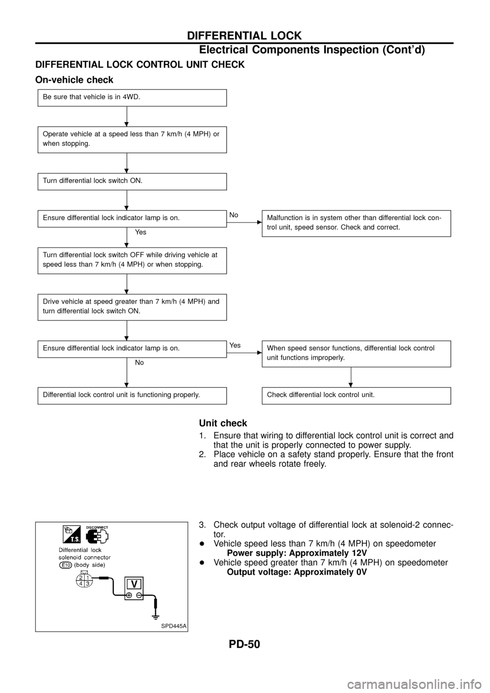
DIFFERENTIAL LOCK CONTROL UNIT CHECK
On-vehicle check
Be sure that vehicle is in 4WD.
Operate vehicle at a speed less than 7 km/h (4 MPH) or
when stopping.
Turn differential lock switch ON.
Ensure differential lock indicator lamp is on.
Ye s
cNo
Malfunction is in system other than differential lock con-
trol unit, speed sensor. Check and correct.
Turn differential lock switch OFF while driving vehicle at
speed less than 7 km/h (4 MPH) or when stopping.
Drive vehicle at speed greater than 7 km/h (4 MPH) and
turn differential lock switch ON.
Ensure differential lock indicator lamp is on.
No
cYe s
When speed sensor functions, differential lock control
unit functions improperly.
Differential lock control unit is functioning properly.Check differential lock control unit.
Unit check
1. Ensure that wiring to differential lock control unit is correct and
that the unit is properly connected to power supply.
2. Place vehicle on a safety stand properly. Ensure that the front
and rear wheels rotate freely.
3. Check output voltage of differential lock at solenoid-2 connec-
tor.
+Vehicle speed less than 7 km/h (4 MPH) on speedometer
Power supply: Approximately 12V
+Vehicle speed greater than 7 km/h (4 MPH) on speedometer
Output voltage: Approximately 0V
SPD445A
.
.
.
.
.
.
..
DIFFERENTIAL LOCK
Electrical Components Inspection (Cont'd)
PD-50