Page 5 of 54
NVH Troubleshooting Chart
Use the chart below to help you ®nd the cause of the symptom. If necessary, repair or replace these parts.
Reference pageÐ
Ð
PD-6
PD-6
PD-19
PD-29
PD-19
PD-14
Ð
Refer to MA section.
Refer to PROPELLER SHAFT in this chart.
Refer to DIFFERENTIAL in this chart.
NVH in FA, RA section
NVH in FA section
NVH in FA section
NVH in RA section
NVH in BR section
NVH in ST section
Possible cause and
SUSPECTED PARTS
Uneven rotation torque
Excessive joint angle
Rotation imbalance
Excessive runout
Rough gear tooth
Improper gear contact
Tooth surfaces worn
Incorrect backlash
Companion ¯ange excessive runout
Improper gear oil
PROPELLER SHAFT
DIFFERENTIAL
AXLE AND SUSPENSION
TIRES
ROAD WHEEL
DRIVE SHAFT
BRAKES
STEERING
SymptomPRO-
PELLER
SHAFTNoiseXXXX XXXXXXX
Shake XXXXXXX
VibrationXXXX XX X X
DIFFER-
ENTIALNoiseXXXXXXX XXXXXX
X: Applicable
NOISE, VIBRATION AND HARSHNESS (NVH) TROUBLESHOOTING
PD-4
Page 7 of 54
On-vehicle Service
PROPELLER SHAFT VIBRATION
If vibration is present at high speed, inspect propeller shaft runout
®rst.
1. Raise front and rear wheels.
2. Measure propeller shaft runout at several points by rotating
®nal drive companion ¯ange with hands.
Runout limit: 0.6 mm (0.024 in)
3. If runout exceeds speci®cations, disconnect propeller shaft at
®nal drive companion ¯ange; then rotate companion ¯ange 180
degrees and reconnect propeller shaft.
4. Check runout again. If runout still exceeds speci®cations,
replace propeller shaft assembly.
5. Perform road tests.
APPEARANCE CHECKING
+Inspect propeller shaft tube surface for dents or cracks. If
damaged, replace propeller shaft assembly.
SPD458A
SPD728
SPD102
PROPELLER SHAFT
PD-6
Page 21 of 54
CAUTION:
Do not run engine when one wheel (rear) is off the ground.
Preparation for Disassembly
CHECKING DIFFERENTIAL TORQUE
Measure differential torque with Tool.
If it is not within the speci®cations, inspect components of limited
slip differential.
Differential torque:
108 - 137 Nzm (11 - 14 kg-m, 80 - 101 ft-lb)
Tool number: KV38106400
SPD439A
SPD508
LIMITED SLIP DIFFERENTIAL
PD-20
Page 51 of 54

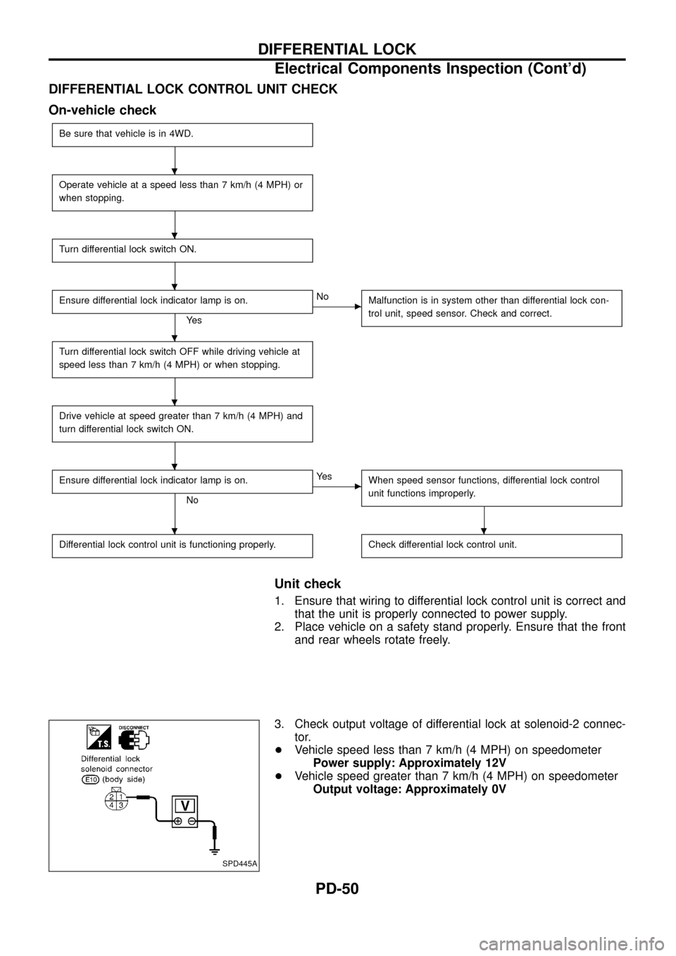
DIFFERENTIAL LOCK CONTROL UNIT CHECK
On-vehicle check
Be sure that vehicle is in 4WD.
Operate vehicle at a speed less than 7 km/h (4 MPH) or
when stopping.
Turn differential lock switch ON.
Ensure differential lock indicator lamp is on.
Ye s
cNo
Malfunction is in system other than differential lock con-
trol unit, speed sensor. Check and correct.
Turn differential lock switch OFF while driving vehicle at
speed less than 7 km/h (4 MPH) or when stopping.
Drive vehicle at speed greater than 7 km/h (4 MPH) and
turn differential lock switch ON.
Ensure differential lock indicator lamp is on.
No
cYe s
When speed sensor functions, differential lock control
unit functions improperly.
Differential lock control unit is functioning properly.Check differential lock control unit.
Unit check
1. Ensure that wiring to differential lock control unit is correct and
that the unit is properly connected to power supply.
2. Place vehicle on a safety stand properly. Ensure that the front
and rear wheels rotate freely.
3. Check output voltage of differential lock at solenoid-2 connec-
tor.
+Vehicle speed less than 7 km/h (4 MPH) on speedometer
Power supply: Approximately 12V
+Vehicle speed greater than 7 km/h (4 MPH) on speedometer
Output voltage: Approximately 0V
SPD445A
.
.
.
.
.
.
..
DIFFERENTIAL LOCK
Electrical Components Inspection (Cont'd)
PD-50