1998 NISSAN PATROL torque
[x] Cancel search: torquePage 3 of 54
Tool number
Tool nameDescriptionUnit application
H233B
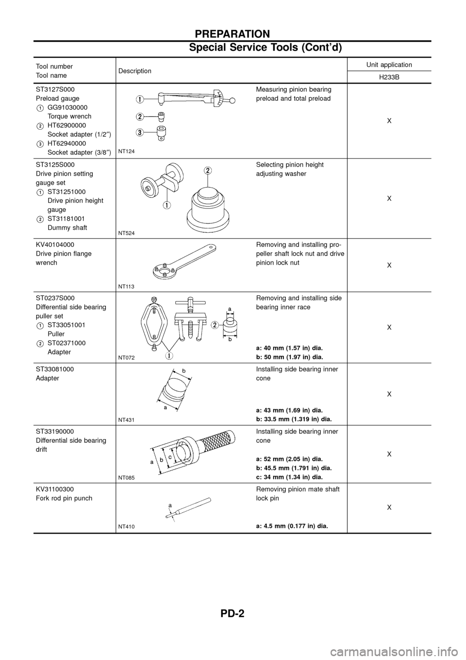
ST3127S000
Preload gauge
V1GG91030000
Torque wrench
V2HT62900000
Socket adapter (1/2²)
V3HT62940000
Socket adapter (3/8²)NT124
Measuring pinion bearing
preload and total preload
X
ST3125S000
Drive pinion setting
gauge set
V1ST31251000
Drive pinion height
gauge
V2ST31181001
Dummy shaft
NT524
Selecting pinion height
adjusting washer
X
KV40104000
Drive pinion ¯ange
wrench
NT113
Removing and installing pro-
peller shaft lock nut and drive
pinion lock nut
X
ST0237S000
Differential side bearing
puller set
V1ST33051001
Puller
V2ST02371000
Adapter
NT072
Removing and installing side
bearing inner race
X
a: 40 mm (1.57 in) dia.
b: 50 mm (1.97 in) dia.
ST33081000
Adapter
NT431
Installing side bearing inner
cone
X
a: 43 mm (1.69 in) dia.
b: 33.5 mm (1.319 in) dia.
ST33190000
Differential side bearing
drift
NT085
Installing side bearing inner
cone
X
a: 52 mm (2.05 in) dia.
b: 45.5 mm (1.791 in) dia.
c: 34 mm (1.34 in) dia.
KV31100300
Fork rod pin punch
NT410
Removing pinion mate shaft
lock pin
X
a: 4.5 mm (0.177 in) dia.
PREPARATION
Special Service Tools (Cont'd)
PD-2
Page 5 of 54
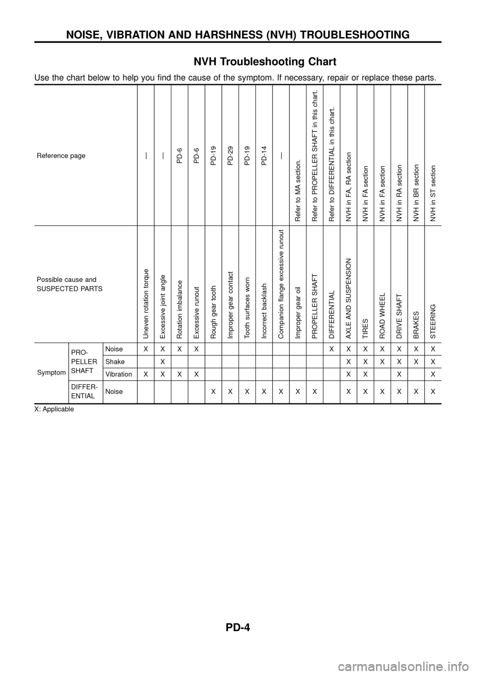
NVH Troubleshooting Chart
Use the chart below to help you ®nd the cause of the symptom. If necessary, repair or replace these parts.
Reference pageÐ
Ð
PD-6
PD-6
PD-19
PD-29
PD-19
PD-14
Ð
Refer to MA section.
Refer to PROPELLER SHAFT in this chart.
Refer to DIFFERENTIAL in this chart.
NVH in FA, RA section
NVH in FA section
NVH in FA section
NVH in RA section
NVH in BR section
NVH in ST section
Possible cause and
SUSPECTED PARTS
Uneven rotation torque
Excessive joint angle
Rotation imbalance
Excessive runout
Rough gear tooth
Improper gear contact
Tooth surfaces worn
Incorrect backlash
Companion ¯ange excessive runout
Improper gear oil
PROPELLER SHAFT
DIFFERENTIAL
AXLE AND SUSPENSION
TIRES
ROAD WHEEL
DRIVE SHAFT
BRAKES
STEERING
SymptomPRO-
PELLER
SHAFTNoiseXXXX XXXXXXX
Shake XXXXXXX
VibrationXXXX XX X X
DIFFER-
ENTIALNoiseXXXXXXX XXXXXX
X: Applicable
NOISE, VIBRATION AND HARSHNESS (NVH) TROUBLESHOOTING
PD-4
Page 21 of 54
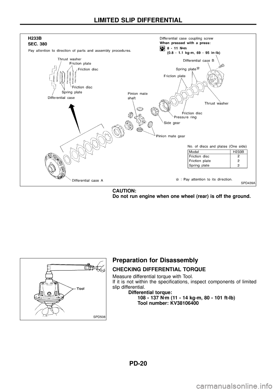
CAUTION:
Do not run engine when one wheel (rear) is off the ground.
Preparation for Disassembly
CHECKING DIFFERENTIAL TORQUE
Measure differential torque with Tool.
If it is not within the speci®cations, inspect components of limited
slip differential.
Differential torque:
108 - 137 Nzm (11 - 14 kg-m, 80 - 101 ft-lb)
Tool number: KV38106400
SPD439A
SPD508
LIMITED SLIP DIFFERENTIAL
PD-20
Page 27 of 54
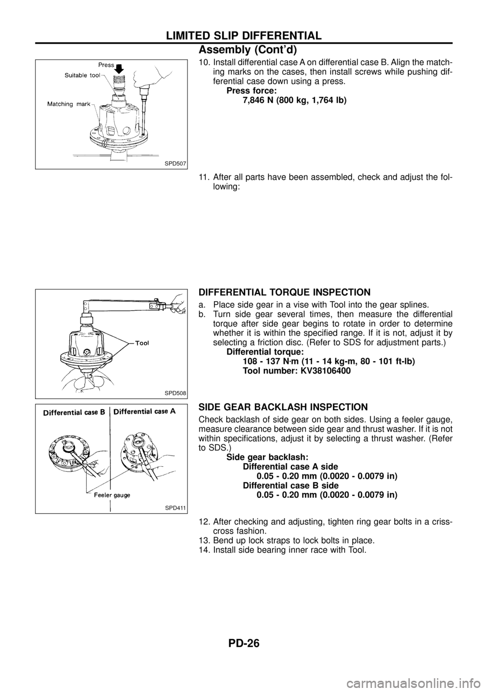
10. Install differential case A on differential case B. Align the match-
ing marks on the cases, then install screws while pushing dif-
ferential case down using a press.
Press force:
7,846 N (800 kg, 1,764 lb)
11. After all parts have been assembled, check and adjust the fol-
lowing:
DIFFERENTIAL TORQUE INSPECTION
a. Place side gear in a vise with Tool into the gear splines.
b. Turn side gear several times, then measure the differential
torque after side gear begins to rotate in order to determine
whether it is within the speci®ed range. If it is not, adjust it by
selecting a friction disc. (Refer to SDS for adjustment parts.)
Differential torque:
108 - 137 Nzm (11 - 14 kg-m, 80 - 101 ft-lb)
Tool number: KV38106400
SIDE GEAR BACKLASH INSPECTION
Check backlash of side gear on both sides. Using a feeler gauge,
measure clearance between side gear and thrust washer. If it is not
within speci®cations, adjust it by selecting a thrust washer. (Refer
to SDS.)
Side gear backlash:
Differential case A side
0.05 - 0.20 mm (0.0020 - 0.0079 in)
Differential case B side
0.05 - 0.20 mm (0.0020 - 0.0079 in)
12. After checking and adjusting, tighten ring gear bolts in a criss-
cross fashion.
13. Bend up lock straps to lock bolts in place.
14. Install side bearing inner race with Tool.
SPD507
SPD508
SPD411
LIMITED SLIP DIFFERENTIAL
Assembly (Cont'd)
PD-26
Page 35 of 54
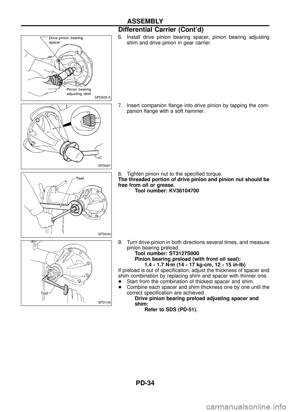
6. Install drive pinion bearing spacer, pinion bearing adjusting
shim and drive pinion in gear carrier.
7. Insert companion ¯ange into drive pinion by tapping the com-
panion ¯ange with a soft hammer.
8. Tighten pinion nut to the speci®ed torque.
The threaded portion of drive pinion and pinion nut should be
free from oil or grease.
Tool number: KV38104700
9. Turn drive pinion in both directions several times, and measure
pinion bearing preload.
Tool number: ST3127S000
Pinion bearing preload (with front oil seal):
1.4 - 1.7 Nzm (14 - 17 kg-cm, 12 - 15 in-lb)
If preload is out of speci®cation, adjust the thickness of spacer and
shim combination by replacing shim and spacer with thinner one.
+Start from the combination of thickest spacer and shim.
+Combine each spacer and shim thickness one by one until the
correct speci®cation are achieved.
Drive pinion bearing preload adjusting spacer and
shim:
Refer to SDS (PD-51).
SPD935-A
SPD697
SPD040
SPD149
ASSEMBLY
Differential Carrier (Cont'd)
PD-34
Page 54 of 54
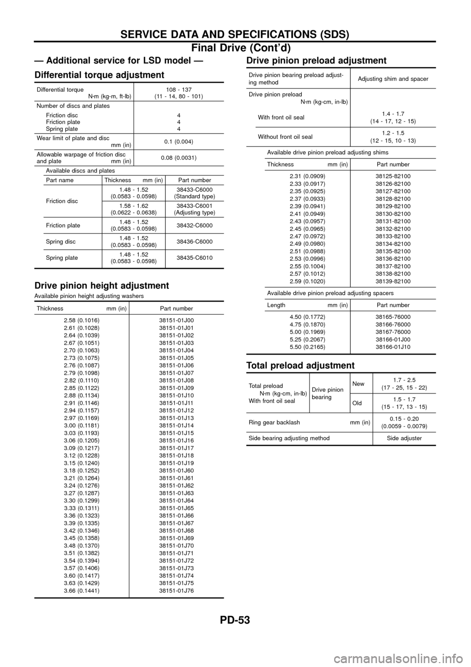
Ð Additional service for LSD model Ð
Differential torque adjustment
Differential torque
Nzm (kg-m, ft-lb)108 - 137
(11 - 14, 80 - 101)
Number of discs and plates
Friction disc
Friction plate
Spring plate4
4
4
Wear limit of plate and disc
mm (in)0.1 (0.004)
Allowable warpage of friction disc
and plate mm (in)0.08 (0.0031)
Available discs and plates
Part name Thickness mm (in) Part number
Friction disc1.48 - 1.52
(0.0583 - 0.0598)38433-C6000
(Standard type)
1.58 - 1.62
(0.0622 - 0.0638)38433-C6001
(Adjusting type)
Friction plate1.48 - 1.52
(0.0583 - 0.0598)38432-C6000
Spring disc1.48 - 1.52
(0.0583 - 0.0598)38436-C6000
Spring plate1.48 - 1.52
(0.0583 - 0.0598)38435-C6010
Drive pinion height adjustment
Available pinion height adjusting washers
Thickness mm (in) Part number
2.58 (0.1016)
2.61 (0.1028)
2.64 (0.1039)
2.67 (0.1051)
2.70 (0.1063)
2.73 (0.1075)
2.76 (0.1087)
2.79 (0.1098)
2.82 (0.1110)
2.85 (0.1122)
2.88 (0.1134)
2.91 (0.1146)
2.94 (0.1157)
2.97 (0.1169)
3.00 (0.1181)
3.03 (0.1193)
3.06 (0.1205)
3.09 (0.1217)
3.12 (0.1228)
3.15 (0.1240)
3.18 (0.1252)
3.21 (0.1264)
3.24 (0.1276)
3.27 (0.1287)
3.30 (0.1299)
3.33 (0.1311)
3.36 (0.1323)
3.39 (0.1335)
3.42 (0.1346)
3.45 (0.1358)
3.48 (0.1370)
3.51 (0.1382)
3.54 (0.1394)
3.57 (0.1406)
3.60 (0.1417)
3.63 (0.1429)
3.66 (0.1441)38151-01J00
38151-01J01
38151-01J02
38151-01J03
38151-01J04
38151-01J05
38151-01J06
38151-01J07
38151-01J08
38151-01J09
38151-01J10
38151-01J11
38151-01J12
38151-01J13
38151-01J14
38151-01J15
38151-01J16
38151-01J17
38151-01J18
38151-01J19
38151-01J60
38151-01J61
38151-01J62
38151-01J63
38151-01J64
38151-01J65
38151-01J66
38151-01J67
38151-01J68
38151-01J69
38151-01J70
38151-01J71
38151-01J72
38151-01J73
38151-01J74
38151-01J75
38151-01J76
Drive pinion preload adjustment
Drive pinion bearing preload adjust-
ing methodAdjusting shim and spacer
Drive pinion preload
Nzm (kg-cm, in-lb)
With front oil seal1.4 - 1.7
(14 - 17, 12 - 15)
Without front oil seal1.2 - 1.5
(12 - 15, 10 - 13)
Available drive pinion preload adjusting shims
Thickness mm (in) Part number
2.31 (0.0909)
2.33 (0.0917)
2.35 (0.0925)
2.37 (0.0933)
2.39 (0.0941)
2.41 (0.0949)
2.43 (0.0957)
2.45 (0.0965)
2.47 (0.0972)
2.49 (0.0980)
2.51 (0.0988)
2.53 (0.0996)
2.55 (0.1004)
2.57 (0.1012)
2.59 (0.1020)38125-82100
38126-82100
38127-82100
38128-82100
38129-82100
38130-82100
38131-82100
38132-82100
38133-82100
38134-82100
38135-82100
38136-82100
38137-82100
38138-82100
38139-82100
Available drive pinion preload adjusting spacers
Length mm (in) Part number
4.50 (0.1772)
4.75 (0.1870)
5.00 (0.1969)
5.25 (0.2067)
5.50 (0.2165)38165-76000
38166-76000
38167-76000
38166-01J00
38166-01J10
Total preload adjustment
Total preload
Nzm (kg-cm, in-lb)
With front oil sealDrive pinion
bearingNew1.7 - 2.5
(17 - 25, 15 - 22)
Old1.5 - 1.7
(15 - 17, 13 - 15)
Ring gear backlash mm (in)0.15 - 0.20
(0.0059 - 0.0079)
Side bearing adjusting method Side adjuster
SERVICE DATA AND SPECIFICATIONS (SDS)
Final Drive (Cont'd)
PD-53