Page 9 of 54
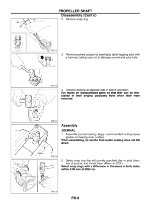
2. Remove snap ring.
3. Remove pushed out journal bearing by lightly tapping yoke with
a hammer, taking care not to damage journal and yoke hole.
4. Remove bearing at opposite side in above operation.
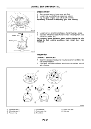
Put marks on disassembled parts so that they can be rein-
stalled in their original positions from which they were
removed.
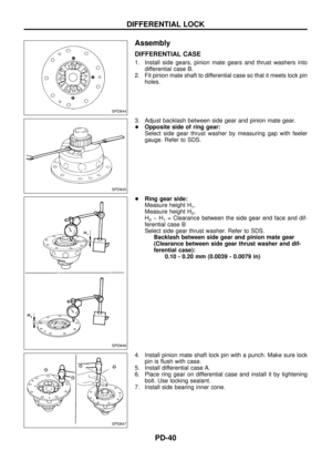
Assembly
JOURNAL
1. Assemble journal bearing. Apply recommended multi-purpose
grease on bearing inner surface.
When assembling, be careful that needle bearing does not fall
down.
2. Select snap ring that will provide speci®ed play in axial direc-
tion of journal, and install them. (Refer to SDS.)
Select snap rings with a difference in thickness at both sides
within 0.06 mm (0.0024 in).
SPD731
SPD732
SPD131
SPD133
SPD134
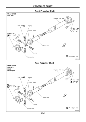
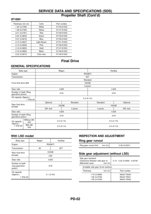
PROPELLER SHAFT
Disassembly (Cont'd)
PD-8
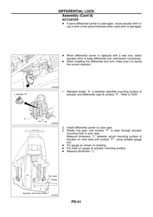
Page 10 of 54
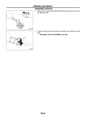
3. Adjust thrust clearance between bearing and snap ring to zero
by tapping yoke.
4. Check to see that journal moves smoothly and check for axial
play.
Axial play: 0.02 mm (0.0008 in) or less
SPD732
SPD874
PROPELLER SHAFT
Assembly (Cont'd)
PD-9
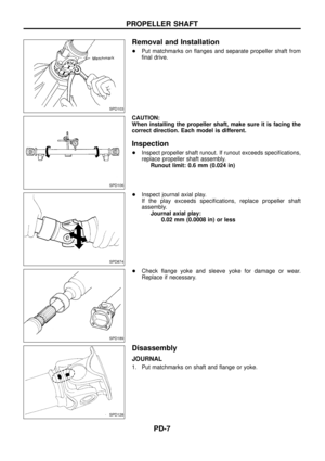
Page 11 of 54
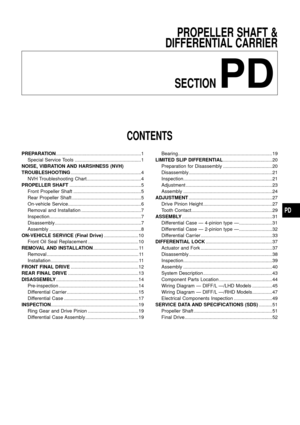
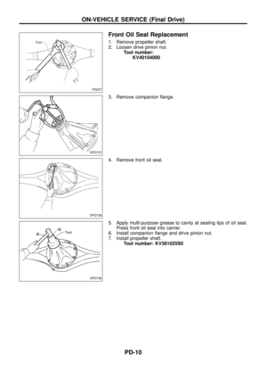
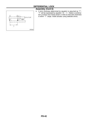
Front Oil Seal Replacement
1. Remove propeller shaft.
2. Loosen drive pinion nut.
Tool number:
KV40104000
3. Remove companion ¯ange.
4. Remove front oil seal.
5. Apply multi-purpose grease to cavity at sealing lips of oil seal.
Press front oil seal into carrier.
6. Install companion ¯ange and drive pinion nut.
7. Install propeller shaft.
Tool number: KV381025S0
PD237
SPD737
SPD738
SPD739
ON-VEHICLE SERVICE (Final Drive)
PD-10
Page 12 of 54
Removal
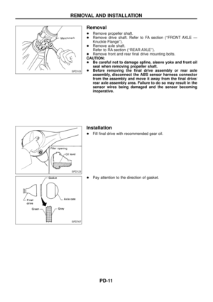
+Remove propeller shaft.
+Remove drive shaft. Refer to FA section (``FRONT AXLE Ð
Knuckle Flange'').
+Remove axle shaft.
Refer to RA section (``REAR AXLE'').
+Remove front and rear ®nal drive mounting bolts.
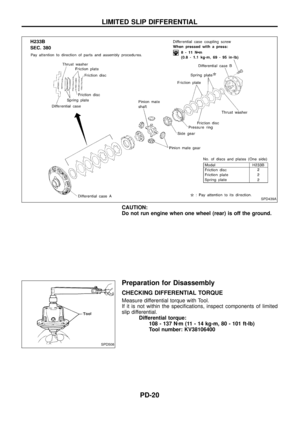
CAUTION:
+Be careful not to damage spline, sleeve yoke and front oil
seal when removing propeller shaft.
+Before removing the ®nal drive assembly or rear axle
assembly, disconnect the ABS sensor harness connector
from the assembly and move it away from the ®nal drive/
rear axle assembly area. Failure to do so may result in the
sensor wires being damaged and the sensor becoming
inoperative.
Installation
+Fill ®nal drive with recommended gear oil.
+Pay attention to the direction of gasket.
SPD103
SPD123
SPD767
REMOVAL AND INSTALLATION
PD-11
Page 13 of 54
SPD436A
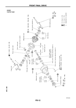
FRONT FINAL DRIVE
PD-12
Page 14 of 54
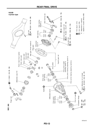
SPD437A
REAR FINAL DRIVE
PD-13
Page 15 of 54
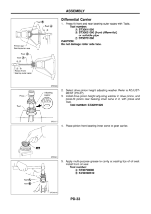
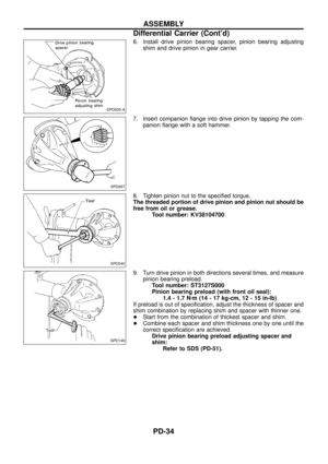
 Turn drive pinion in both directions several times to set bearing
rollers.
2) Check total preload w")
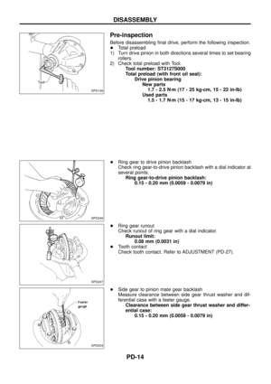
Pre-inspection
Before disassembling ®nal drive, perform the following inspection.
+Total preload
1) Turn drive pinion in both directions several times to set bearing
rollers.
2) Check total preload with Tool.
Tool number: ST3127S000
Total preload (with front oil seal):
Drive pinion bearing
New parts
1.7 - 2.5 Nzm (17 - 25 kg-cm, 15 - 22 in-lb)
Used parts
1.5 - 1.7 Nzm (15 - 17 kg-cm, 13 - 15 in-lb)
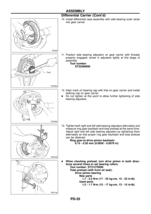
+Ring gear to drive pinion backlash
Check ring gear-to-drive pinion backlash with a dial indicator at
several points.
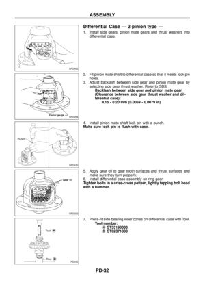
Ring gear-to-drive pinion backlash:
0.15 - 0.20 mm (0.0059 - 0.0079 in)
+Ring gear runout
Check runout of ring gear with a dial indicator.
Runout limit:
0.08 mm (0.0031 in)
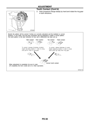
+Tooth contact
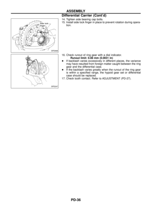
Check tooth contact. Refer to ADJUSTMENT (PD-27).
+Side gear to pinion mate gear backlash
Measure clearance between side gear thrust washer and dif-
ferential case with a feeler gauge.
Clearance between side gear thrust washer and differ-
ential case:
0.15 - 0.20 mm (0.0059 - 0.0079 in)
SPD149
SPD246
SPD247
SPD004
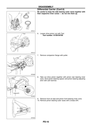
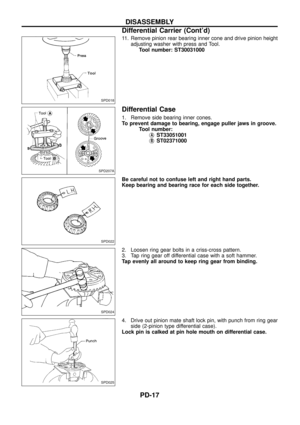
DISASSEMBLY
PD-14
Page 16 of 54
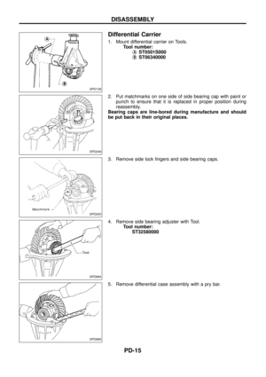
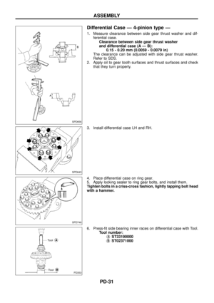
Differential Carrier
1. Mount differential carrier on Tools.
Tool number:
j
AST0501S000
j
BST06340000
2. Put matchmarks on one side of side bearing cap with paint or
punch to ensure that it is replaced in proper position during
reassembly.
Bearing caps are line-bored during manufacture and should
be put back in their original places.
3. Remove side lock ®ngers and side bearing caps.
4. Remove side bearing adjuster with Tool.
Tool number:
ST32580000
5. Remove differential case assembly with a pry bar.
SPD139
SPD249
SPD250
SPD684
SPD685
DISASSEMBLY
PD-15

 or less
SPD732
S")

.
+Remove axle shaft.
Refer to RA section (``REAR AXLE).
+Remove front and rear ®nal driv")


