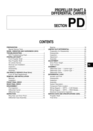
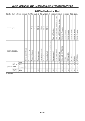
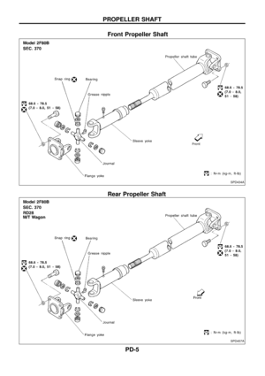
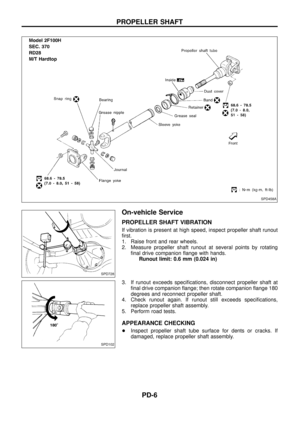
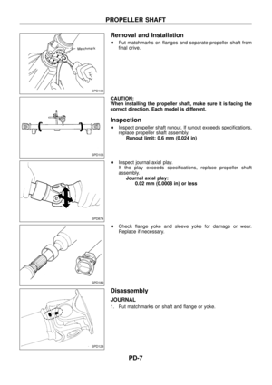
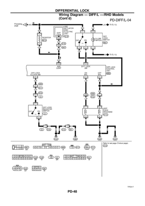
Page 25 of 54
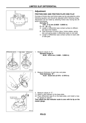
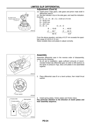
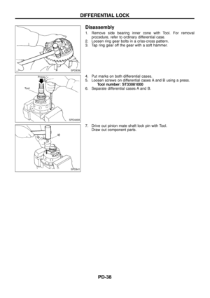
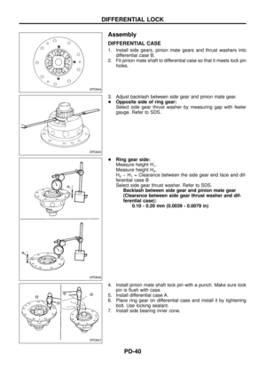
 Install pinion mate gears, side gears and pinion mate shaft in
differential case B.
(4) Set dial indicators tip on the side gear, and read the indication.
Example:
E = A þ D = A þ (B + C) = 0.0")
(3) Install pinion mate gears, side gears and pinion mate shaft in
differential case B.
(4) Set dial indicator's tip on the side gear, and read the indication.
Example:
E = A þ D = A þ (B + C) = 0.05 to 0.15 mm
A = 49.52 mm
B = 19.45 mm
C = 29.7 mm
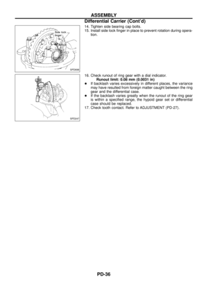
D=B+C E=AþD
B .... 19.45 A ..... 49.52
+C .... 29.7 þD .... 49.15
49.150.37
From the above equation, end play of 0.37 mm exceeds the speci-
®ed range of 0.05 to 0.15 mm.
Select suitable discs and plates to adjust correctly.
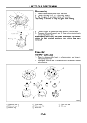
Assembly
Assemble differential case in the reverse order of disassembly,
observing the following.
1. As an aid to installation, apply sufficient amounts of recom-
mended limited slip differential gear oil (refer to MA section) to
the faces of pressure rings, discs and plates to be assembled
together.
2. Place differential case B on a level surface, then install thrust
washer.
3. Install spring plates, friction plates and friction discs.
Pay particular attention to the direction of clutch plates and
their assembly sequence.
SPD419
SPD479
SPD406
SPD504
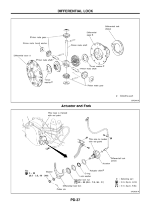
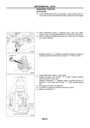
LIMITED SLIP DIFFERENTIAL
Adjustment (Cont'd)
PD-24
Page 26 of 54
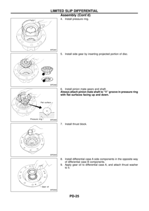
4. Install pressure ring.
5. Install side gear by inserting projected portion of disc.
6. Install pinion mate gears and shaft.
Always attach pinion mate shaft to ``V'' groove in pressure ring
with ¯at surfaces facing up and down.
7. Install thrust block.
8. Install differential case A side components in the opposite way
of differential case B components.
9. Apply gear oil to differential case A, and attach thrust washer
to it.
SPD481
SPD482
SPD483
SPD505
SPD506
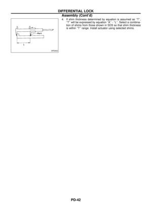
LIMITED SLIP DIFFERENTIAL
Assembly (Cont'd)
PD-25
Page 27 of 54

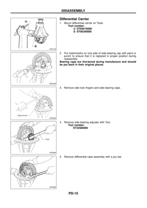
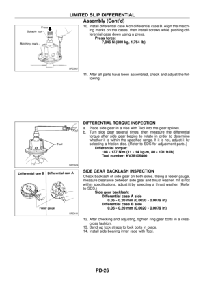
10. Install differential case A on differential case B. Align the match-
ing marks on the cases, then install screws while pushing dif-
ferential case down using a press.
Press force:
7,846 N (800 kg, 1,764 lb)
11. After all parts have been assembled, check and adjust the fol-
lowing:
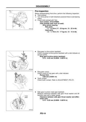
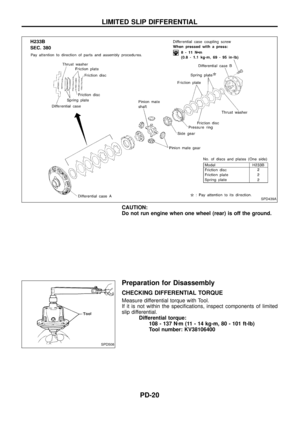
DIFFERENTIAL TORQUE INSPECTION
a. Place side gear in a vise with Tool into the gear splines.
b. Turn side gear several times, then measure the differential
torque after side gear begins to rotate in order to determine
whether it is within the speci®ed range. If it is not, adjust it by
selecting a friction disc. (Refer to SDS for adjustment parts.)
Differential torque:
108 - 137 Nzm (11 - 14 kg-m, 80 - 101 ft-lb)
Tool number: KV38106400
SIDE GEAR BACKLASH INSPECTION
Check backlash of side gear on both sides. Using a feeler gauge,
measure clearance between side gear and thrust washer. If it is not
within speci®cations, adjust it by selecting a thrust washer. (Refer
to SDS.)
Side gear backlash:
Differential case A side
0.05 - 0.20 mm (0.0020 - 0.0079 in)
Differential case B side
0.05 - 0.20 mm (0.0020 - 0.0079 in)
12. After checking and adjusting, tighten ring gear bolts in a criss-
cross fashion.
13. Bend up lock straps to lock bolts in place.
14. Install side bearing inner race with Tool.
SPD507
SPD508
SPD411
LIMITED SLIP DIFFERENTIAL
Assembly (Cont'd)
PD-26
Page 28 of 54
To avoid confusion while calculating bearing shims, it is absolutely
necessary to stay with the metric system. If you measure anything
in inches,the results must be converted to the metric system.
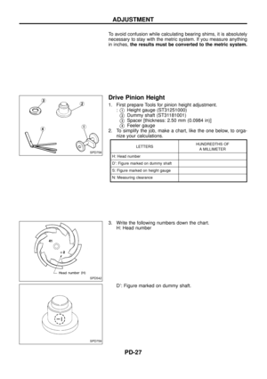
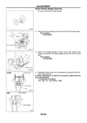
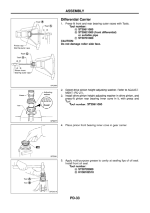
Drive Pinion Height
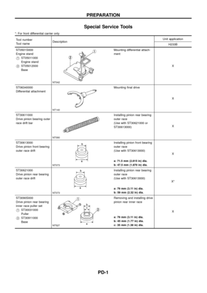
1. First prepare Tools for pinion height adjustment.
:
V1Height gauge (ST31251000)
V2Dummy shaft (ST31181001)
V3Spacer [thickness: 2.50 mm (0.0984 in)]
V4Feeler gauge
2. To simplify the job, make a chart, like the one below, to orga-
nize your calculations.
LETTERSHUNDREDTHS OF
A MILLIMETER
H: Head number
D¢: Figure marked on dummy shaft
S: Figure marked on height gauge
N: Measuring clearance
3. Write the following numbers down the chart.
H: Head number
D¢: Figure marked on dummy shaft.
SPD758
SPD542
SPD759
ADJUSTMENT
PD-27
Page 29 of 54
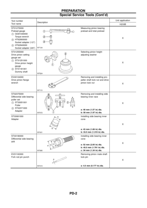
S: Figure marked on height gauge.
4. Place pinion rear bearing inner cone and Tools on gear carrier.
Tool number:
ST31181001
5. Attach Tool (Height gauge) to gear carrier, and measure the
clearance between the height gauge tip and the dummy shaft
face.
Tool number:
ST31251000
6. Substitute these values into the equation to calculate the thick-
ness of the washer.
If values signifying H, D¢and S are not given, regard them as
zero and calculate.
T (Thickness of washer)
=Nþ[(HþD¢þ S) x 0.01] + 3.05
SPD760
SPD271-A
SPD272-A
PD444-A
PD029
ADJUSTMENT
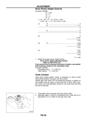
Drive Pinion Height (Cont'd)
PD-28
Page 30 of 54
![NISSAN PATROL 1998 Y61 / 5.G Propeller Shaft And Differential Carrier Workshop Manual Example (H233B):
N = 0.30
H=2
D¢=þ1
S=0
T=Nþ[(HþD¢þ S) x 0.01] + 3.05
= 0.30 þ [{2 þ (þ1) þ 0} x 0.01] + 3.05
(1) H ........................................................................ 2](/manual-img/5/625/w960_625-29.png "NISSAN PATROL 1998 Y61 / 5.G Propeller Shaft And Differential Carrier Workshop Manual Example (H233B):
N = 0.30
H=2
D¢=þ1
S=0
T=Nþ[(HþD¢þ S) x 0.01] + 3.05
= 0.30 þ [{2 þ (þ1) þ 0} x 0.01] + 3.05
(1) H ........................................................................ 2")
Example (H233B):
N = 0.30
H=2
D¢=þ1
S=0
T=Nþ[(HþD¢þ S) x 0.01] + 3.05
= 0.30 þ [{2 þ (þ1) þ 0} x 0.01] + 3.05
(1) H ........................................................................ 2
þD¢................................................................. þ(þ1)
3
þS ...................................................................... þ0
3
(2) 3
x 0.01
0.03
(3) N ................................................................... 0.30
þ0.03
0.27
(4) 0.27
+3.05
3.32
\T = 3.32
7. Select the proper pinion height washer.
Drive pinion height adjusting washer:
Refer to SDS (PD-0, 53).
If you cannot ®nd the desired thickness of washer, use washer
with thickness closest to the calculated value.
Example (H233B):
Calculated value ... T = 3.32 mm
Used washer ... T = 3.33 mm
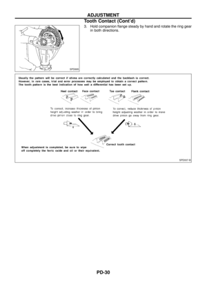
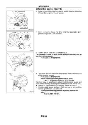
Tooth Contact
Gear tooth contact pattern check is necessary to verify correct
relationship between ring gear and drive pinion.
Hypoid gear sets which are not positioned properly in relation to
one another may be noisy, or have short life or both. With a pat-
tern check, the most desirable contact for low noise level and long
life can be assured.
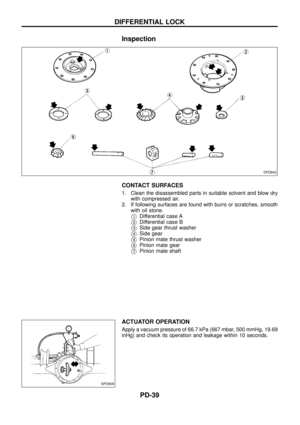
1. Thoroughly clean ring gear and drive pinion teeth.
2. Sparingly apply a mixture of powdered ferric oxide and oil or
equivalent to 3 or 4 teeth of ring gear drive side.
SPD005
ADJUSTMENT
Drive Pinion Height (Cont'd)
PD-29
Page 31 of 54
3. Hold companion ¯ange steady by hand and rotate the ring gear
in both directions.
SPD695
SPD007-B
ADJUSTMENT
Tooth Contact (Cont'd)
PD-30
Page 32 of 54
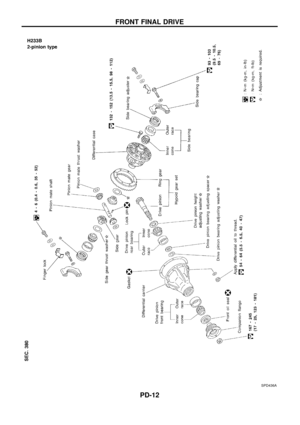
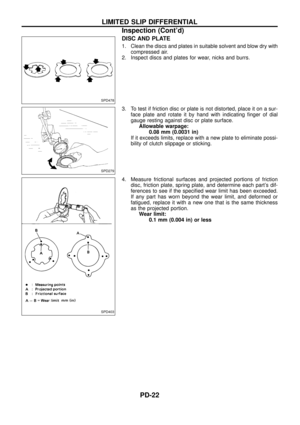
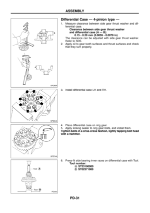
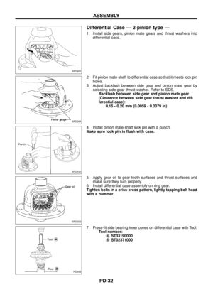
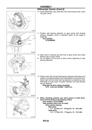
Differential Case Ð 4-pinion type Ð
1. Measure clearance between side gear thrust washer and dif-
ferential case.
Clearance between side gear thrust washer
and differential case (A Ð B):
0.15 - 0.20 mm (0.0059 - 0.0079 in)
The clearance can be adjusted with side gear thrust washer.
Refer to SDS.
2. Apply oil to gear tooth surfaces and thrust surfaces and check
that they turn properly.
3. Install differential case LH and RH.
4. Place differential case on ring gear.
5. Apply locking sealer to ring gear bolts, and install them.
Tighten bolts in a criss-cross fashion, lightly tapping bolt head
with a hammer.
6. Press-®t side bearing inner races on differential case with Tool.
Tool number:
j
AST33190000
j
BST02371000
SPD656
SPD643
SPD746
PD353
ASSEMBLY
PD-31


 to gear carrier, and measure the
clearance be")

PD-30")
:
0.15 - 0.2")