Page 1128 of 2490
Intake Air Distribution and Filtering - Supercharger
Remo
val and Installation
Remov
a
l
Installation
1. Disc onne
ct battery ground cable (IMPORTANT, see SRO
86.15.19 for further information).
2. Drain radiator coolant; refer to 26.10.01.
3. Remove air cleaner cover / intake assembly; refer to 19.10.30.
4. Remove throttle body; refer to 19.70.04.
5. Remove exhaust gas re-circulation valve (EGR) if installed;
refer to 17.45.01.
6. Remove throttle intake elbo w; refer to (SC) 19.70.28.
7. Remove supercharger outlet duct; refer to 18.50.16.
8. Remove coolant outlet pipe; refe r to operation (SC) 26.31.08.
9. Remove supercharger drive belt; refer to 18.50.08.
10. Disconnect remaining coolant hoses from charge air coolers.
Position pipes to facilitate removal
of supercharger.
Inst
al
l suitable blanking plugs.
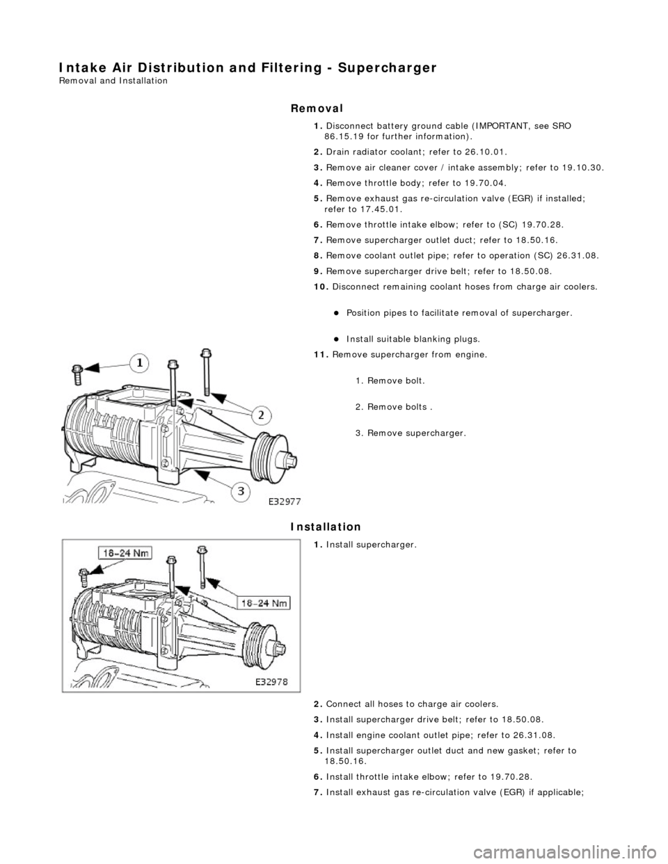
11 .
R
emove supercharger from engine.
1. Remove bolt.
2. Remove bolts .
3. Remove supercharger.
1. Inst al
l supercharger.
2. Connect all hoses to charge air coolers.
3. Install supercharger driv e belt; refer to 18.50.08.
4. Install engine coolant outlet pipe; refer to 26.31.08.
5. Install supercharger outlet du ct and new gasket; refer to
18.50.16.
6. Install throttle intake elbow; refer to 19.70.28.
7. Install exhaust gas re-circulation valve (EGR) if applicable;
Page 1130 of 2490
Intake Air Distribution and Filtering - Supercharger Outlet Pipe
Remo
val and Installation
Remov
a
l
1.
Re
move air cleaner cover / intake
assembly; refer to 19.10.30.
2. Drain radiator coolant; refer to operation (SC) 26.10.01.
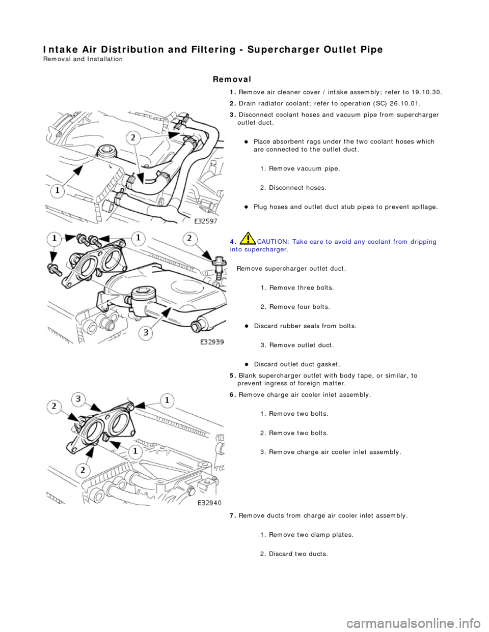
3. Disc
onnect coolant hoses and vacuum pipe from supercharger
outlet duct.
Pl a
ce absorbent rags under
the two coolant hoses which
are connected to the outlet duct.
1. Remove vacuum pipe.
2. Disconnect hoses.
Plu g
hoses and outlet duct stub pipes to prevent spillage.
4. CAUTIO
N: Take care to avoi
d any coolant from dripping
into supercharger.
Remove supercharger outlet duct. 1. Remove three bolts.
2. Remove four bolts.
Di
scard rubber seals from bolts.
3. Remove outlet duct.
Discard ou
tlet duct gasket.
5.
Bla
nk supercharger outlet with
body tape, or similar, to
prevent ingress of foreign matter.
6. Remove charge air c oo
ler inlet assembly.
1. Remove two bolts.
2. Remove two bolts.
3. Remove charge air cooler inlet assembly.
7. Remove ducts from charge air cooler inlet assembly.
1. Remove two clamp plates.
2. Discard two ducts.
Page 1132 of 2490
4. Secure charge air cool
er inlet as
sembly to supercharger outlet
duct.
1. Install bolts.
5. Inst al
l coolant hoses and vacuum pipe to outlet duct.
1. Install vacuum pipe.
2. Install coolant hoses.
6. Refill cooling system; refer to (SC) (26.10.01).
7. Install intake tube / air fl ow meter / air cleaner cover
assembly; refer to 19.10.30.
Page 1134 of 2490
Intake Air Distribution and Filtering - Thrott
le Body Elbow
Re
mo
val and Installation
Remov
a
l
1.
WARNING: B E
FORE PROCEEDING, IT IS ESSENTIAL THAT
WARNING NOTES GIVEN IN SECTION 100-00 (UNDER HEADING
'SAFETY PRECAUTIONS') AR E READ AND UNDERSTOOD.
Disconnect battery ground cable (IMPORTANT, see SRO
86.15.19 for further information).
2. Re
move air cleaner cover / inta
ke assembly; refer 19.10.30.
3. Remove throttle assemb ly; refer to 19.70.04.
4. Remove exhaust gas recirculation (EGR) valve where installed;
refer 17.45.01.
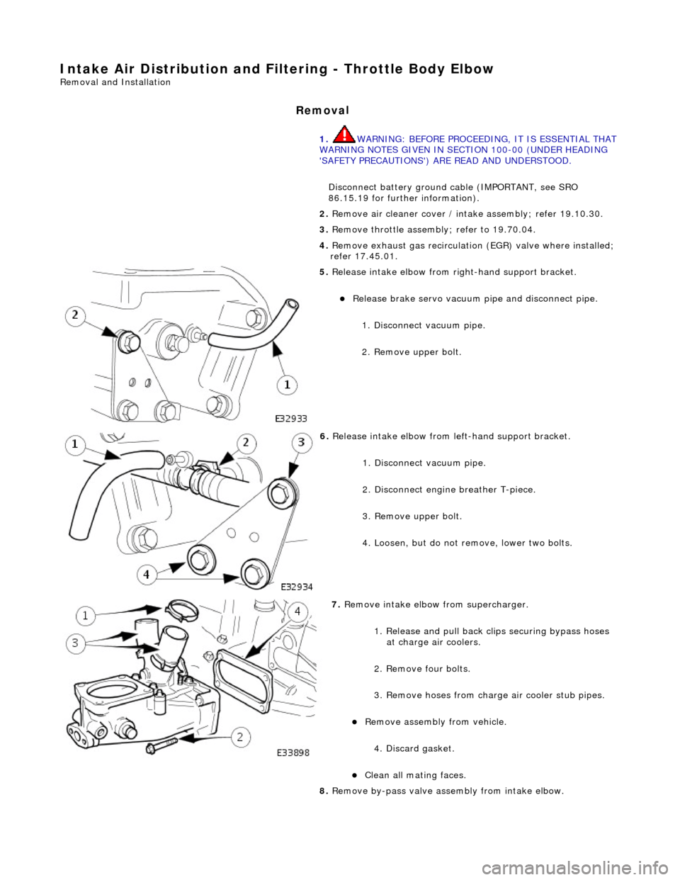
5. Re
lease intake elbow from right-hand support bracket.
Re
lea
se brake servo vacuum pi
pe and disconnect pipe.
1. Disconnect vacuum pipe.
2. Remove upper bolt.
6. Relea
se intake elbow from le
ft-hand support bracket.
1. Disconnect vacuum pipe.
2. Disconnect engine breather T-piece.
3. Remove upper bolt.
4. Loosen, but do not remove, lower two bolts.
7. Re
move intake elbow from supercharger.
1. Release and pull back cl ips securing bypass hoses
at charge air coolers.
2. Remove four bolts.
3. Remove hoses from charge air cooler stub pipes.
Re move as
sembly from vehicle.
4. Discard gasket.
Cle a
n all mating faces.
8. Remove by-pass valve assembly from intake elbow.
Page 1135 of 2490
I
nstallation
1.
Remove two bolts.
Re
move by-pass assembly from
elbow and discard O-ring.
9. Where necessary, remove blanki ng plate from intake elbow.
Re
move bolts.
Di
scard gasket.
Cle
an all mating faces.
1. Where necessary, install blanking plate to intake elbow.
Inst
all new gasket.
Inst
all bolts (18-24Nm).
2. Inst
all by-pass valve assembly to intake elbow.
Inst
all new O-ring and lubricate with petroleum jelly.
1. Install bolts.
3. Install
intake elbow to supercharger.
1. Install two bolts to intake elbow and install new gasket.
2. Position intake elbow assembly with by-pass hoses located on charge air cooler stub pipes.
3. Install and tighten four bolts .
4. Position hose securing clips.
4. Install left-hand support brac ket to intake elbow and re-
connect pipework.
1. Install bolt.
Page 1142 of 2490
Intake Air Distribution and Filtering - Throttle B
ody Elbow4.0L SC V8 -
AJ26
Re mo
val and Installation
Remova
l
1.
WARNING: BE
FORE PROCEEDING, IT IS ESSENTIAL THAT
WARNING NOTES GIVEN IN SECTION 100-00 (UNDER HEADING
'SAFETY PRECAUTIONS') AR E READ AND UNDERSTOOD.
Disconnect battery ground cable (IMPORTANT, see SRO
86.15.19 for further information).
2. Re
move air cleaner cover / inta
ke assembly; refer 19.10.30.
3. Remove throttle assemb ly; refer to 19.70.04.
4. Remove exhaust gas recirculation (EGR) valve where installed;
refer 17.45.01.
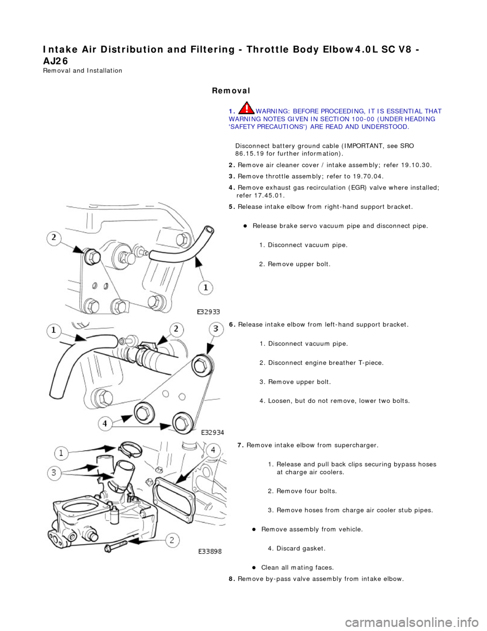
5. Re
lease intake elbow from right-hand support bracket.
Re
lea
se brake servo vacuum pi
pe and disconnect pipe.
1. Disconnect vacuum pipe.
2. Remove upper bolt.
6. Relea
se intake elbow from le
ft-hand support bracket.
1. Disconnect vacuum pipe.
2. Disconnect engine breather T-piece.
3. Remove upper bolt.
4. Loosen, but do not remove, lower two bolts.
7. Re
move intake elbow from supercharger.
1. Release and pull back cl ips securing bypass hoses
at charge air coolers.
2. Remove four bolts.
3. Remove hoses from charge air cooler stub pipes.
Re move as
sembly from vehicle.
4. Discard gasket.
Cle a
n all mating faces.
8. Remove by-pass valve assembly from intake elbow.
Page 1143 of 2490
I
nstallation
1.
Remove two bolts.
Re
move by-pass assembly from
elbow and discard O-ring.
9. Where necessary, remove blanki ng plate from intake elbow.
Re
move bolts.
Di
scard gasket.
Cle
an all mating faces.
1. Where necessary, install blanking plate to intake elbow.
Inst
all new gasket.
Inst
all bolts (18-24Nm).
2. Inst
all by-pass valve assembly to intake elbow.
Inst
all new O-ring and lubricate with petroleum jelly.
1. Install bolts.
3. Install
intake elbow to supercharger.
1. Install two bolts to intake elbow and install new gasket.
2. Position intake elbow assembly with by-pass hoses located on charge air cooler stub pipes.
3. Install and tighten four bolts .
4. Position hose securing clips.
4. Install left-hand support brac ket to intake elbow and re-
connect pipework.
1. Install bolt.
Page 1163 of 2490
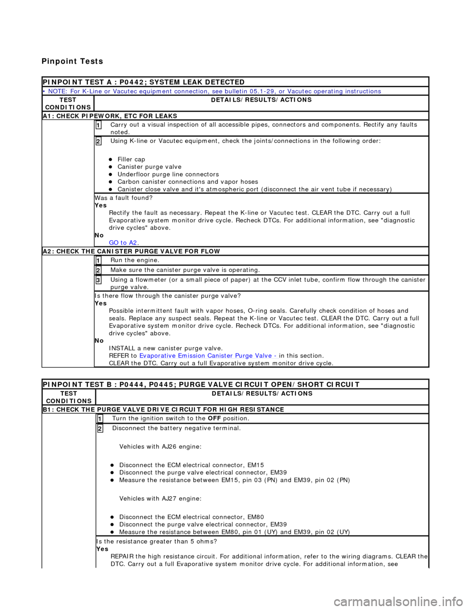
Pinpoint Tests
P
INPOINT TEST A : P0442; SYSTEM LEAK DETECTED
•
NOTE: For K-Line or Vacutec equipment connection, see bulletin 05.1-29, or Vacutec operating instructions
TE
ST
CONDITIONS
D
ETAILS/RESULTS/ACTIONS
A
1: CHECK PIPEWORK, ETC FOR LEAKS
Carr
y out a visual inspection of all accessible pipes, connectors and components. Rectify any faults
noted.
1
U
sing K-line or Vacutec equipment, check the
joints/connections in the following order:
Fi
ller cap
Cani
ster purge valve
Underfl
oor purge line connectors
Carbon
canister connections and vapor hoses
Cani
ster close valve and it's atmospheric port (disconnect the air vent tube if necessary)
2
Was
a fault found?
Yes Rectify the fault as necessary. Re peat the K-line or Vacutec test. CLEAR the DTC. Carry out a full
Evaporative system monitor drive cycle. Recheck DT Cs. For additional information, see "diagnostic
drive cycles" above.
No GO to A2
.
A2: CHECK
THE CA
NISTER PURGE VALVE FOR FLOW
Ru
n the engine.
1
Make sure the canister purge
valve is operating.
2
Using a flowmeter
(or a small piece
of paper) at the CCV inlet tube, confirm flow through the canister
purge valve.
3
Is th
ere flow through the canister purge valve?
Yes Possible intermittent faul t with vapor hoses, O-ring seals. Carefully check condition of hoses and
seals. Replace any suspect seals. Repeat the K-line or Vacutec test. CLEAR the DTC. Carry out a full
Evaporative system monitor drive cycle. Recheck DT Cs. For additional information, see "diagnostic
drive cycles" above.
No INSTALL a new canister purge valve.
REFER to Evaporative Emission Canister Purge Valve
- in t
his section.
CLEAR the DTC. Carry out a full Evap orative system monitor drive cycle.
P
INPOINT TEST B : P0444, P0445; PURGE VALVE CIRCUIT OPEN/SHORT CIRCUIT
TE
ST
CONDITIONS
D
ETAILS/RESULTS/ACTIONS
B1: CHECK
THE PURGE VALVE DRIV
E CIRCUIT FOR HIGH RESISTANCE
Turn the ignition swi
tch to the OFF
position.
1
Di
sconnect the battery negative terminal.
Vehicles with AJ26 engine:
Disc
onnect the ECM electrical connector, EM15
Di
sconnect the purge valve electrical connector, EM39
Meas
ure the resistance between EM15,
pin 03 (PN) and EM39, pin 02 (PN)
Vehicles with AJ27 engine:
Disc
onnect the ECM electrical connector, EM80
Di
sconnect the purge valve electrical connector, EM39
Meas
ure the resistance between EM80, pin 01 (UY) and EM39, pin 02 (UY)
2
Is th
e resistance greater than 5 ohms?
Yes REPAIR the high resistance circuit. For additional information, refer to the wiring diagrams. CLEAR the
DTC. Carry out a full Evaporative system monitor drive cycle. For additional information, see