Page 490 of 2490

Power Steering - Power Steering
Diagn
osis and Testing
Refer to the Description and Operation sub-section for details of the power operated steering system and Servotronic control
system.
Power Steer ing Pressure Test
Test Equ
i
pment
Parts List
In
stalling Test Equipment
To
in
stall the pressure test equipment:
Pla
c
e a suitable drain tray below the PAS pump.
Install a hose clamp
on
the re
servoir to pump hose prior to disconnecting any hoses, to avoid unnecessary loss of
fluid.
Di sc
onnect the hose from the PAS pump high pres
sure outlet.
Ins
tall the pump outlet to hose ad
aptor. Do not omit the O-ring.
Conn
ect the pump adaptor to control valve hose of the test equipment.
Install th
e adaptor in the high pressure hose previ
ously re
moved from the pump outlet.
Conne
ct the connector of the test equipment hose to the adaptor.
R
e
move the hose clamp fro
m the reservoir hose.
Start th
e engine.
With the control valve OPEN and the engine idling , the following system pressures may be checked:
Du
ring turning.
W
h
en the steering is
held on full lock.
With
the steeri
ng at rest.
• WARNINGS:
TO AVOID EXCESSIVE HEATING OF THE PAS PUMP, DO NOT CLOSE THE VALVE FOR LONGER THAN NECESSARY.
Ite
m
Par
t
Number
De
scr
iption
1—Pressure
gauge hose
2—Pump return hose
3—Pump return hose connector
4—Test equi
pment to
HP hose adaptor
5—Pump HP outlet to hose adaptor
6—Pump adaptor
to control valve hose
7—Control valve
Page 611 of 2490

E
ngine - Cylinder Head LH
In-ve
hicle Repair
Remova
l
CAU
TION: If a replacement cylinder head is to be installed to a
vehicle with variable camshaft timing (VCT) the cylinder head m ust have the
oil gallery blind rivet removed before installation.
Spe
cial Tool(s)
Cams
haft setting
303-530
Ti
ming chain tensioning
303-532
Wedges, prim
ary chain
303-533
Cr
ankshaft setting
303-531
1.
Open the engine compartment and install paintwork protection sheets.
2. Set the engine compartment cover to the service access position.
3.
Disconnect the battery ground cable.
Re
move the battery cover.
4. Remove the engine fron cover.For additional information, refer to: Engine
Front Cover (303-01 Engi
ne, In-vehicle Repair).
5. Remove the Inlet Manifold. Refer to Operation 30.15.01 in this Section. This operation includes depressurising the fuel system and removing the throttle
housing.
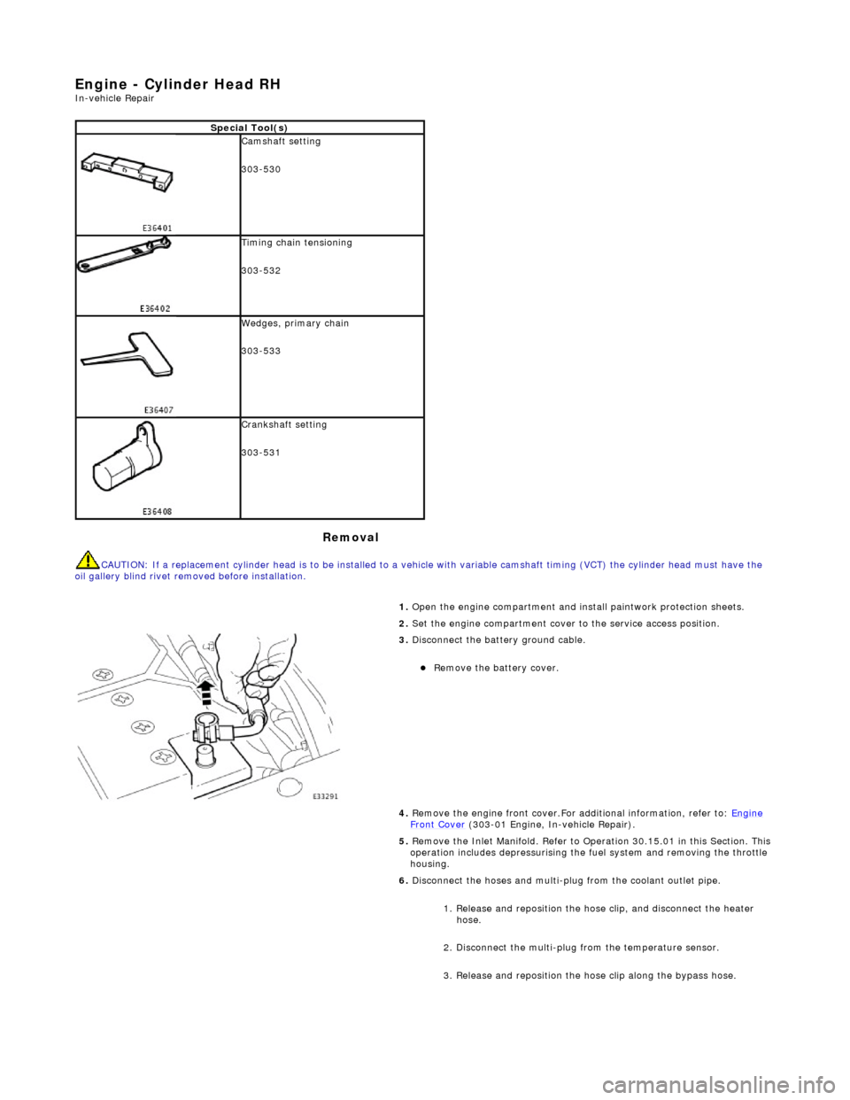
6. Disconnect the hoses and multi-plug from the coolant outlet pipe.
1. Release and reposition the hose clip, and disconnect the heater hose.
2. Disconnect the multi-plug from the temperature sensor.
3. Release and reposition the hose clip along the bypass hose.
Page 625 of 2490

d
ownpipe catalyst.
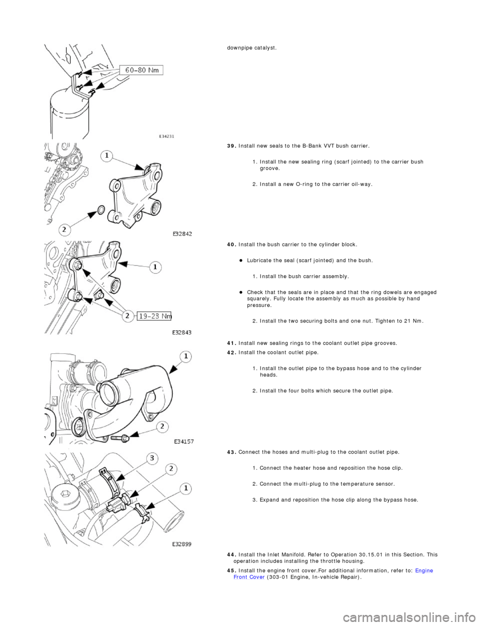
39
.
Install new seals to the B-Bank VVT bush carrier.
1. Install the new sealing ring (scarf jointed) to the carrier bush groove.
2. Install a new O-ring to the carrier oil-way.
40
.
Install the bush carrier to the cylinder block.
Lu
bricate the seal (scarf
jointed) and the bush.
1. Install the bush carrier assembly.
Chec
k that the seals are
in place and that the ri ng dowels are engaged
squarely. Fully locate the assembly as much as possible by hand
pressure.
2. Install the two securing bolts and one nut. Tighten to 21 Nm.
41. Install new sealing rings to the coolant outlet pipe grooves.
42
.
Install the coolant outlet pipe.
1. Install the outlet pipe to the bypass hose and to the cylinder heads.
2. Install the four bolts which secure the outlet pipe.
43
.
Connect the hoses and multi-plug to the coolant outlet pipe.
1. Connect the heater hose and reposition the hose clip.
2. Connect the multi-plug to the temperature sensor.
3. Expand and reposition the hose clip along the bypass hose.
44. Install the Inlet Manifold. Refer to Operation 30.15.01 in this Section. This
operation includes installing the throttle housing.
45. Install the engine front cover.For additional information, refer to: Engine
Front Cover (303-01 Engi
ne, In-vehicle Repair).
Page 627 of 2490

E
ngine - Cylinder Head RH
In-ve
hicle Repair
Remova
l
CAU
TION: If a replacement cylinder head is to be installed to a
vehicle with variable camshaft timing (VCT) the cylinder head m ust have the
oil gallery blind rivet removed before installation.
Spe
cial Tool(s)
Cams
haft setting
303-530
Ti
ming chain tensioning
303-532
Wedges, prim
ary chain
303-533
Cr
ankshaft setting
303-531
1.
Open the engine compartment and install paintwork protection sheets.
2. Set the engine compartment cover to the service access position.
3.
Disconnect the battery ground cable.
Re
move the battery cover.
4. Remove the engine front cover.For additional information, refer to: Engine
Front Cover (303-01 Engi
ne, In-vehicle Repair).
5. Remove the Inlet Manifold. Refer to Operation 30.15.01 in this Section. This operation includes depressurising the fuel system and removing the throttle
housing.
6. Disconnect the hoses and multi-plug from the coolant outlet pipe.
1. Release and reposition the hose clip, and disconnect the heater hose.
2. Disconnect the multi-plug from the temperature sensor.
3. Release and reposition the hose clip along the bypass hose.
Page 640 of 2490

2. In
stall the access grommet to the housing.
36. Lower the ramp.
37. Ins
tall and tighten the nuts which secure the exhaust manifold to the
downpipe catalyst.
38 . In
stall new seals to the A-Bank VVT bush carrier.
1. Install the new sealing ring (scarf jointed) to the carrier bush groove.
2. Install a new O-ring to the carrier oil-way.
39 . Install the bush c
arrier to the cylinder block.
Lu
br
icate the seal (scarf
jointed) and the bush.
1. Install the bush carrier assembly.
Chec k that
the seals are
in place and that the ri ng dowels are engaged
squarely. Fully locate the assembly as much as possible by hand
pressure.
2. Install the three securing bolts. Tighten to 21 Nm.
40. Install new sealing rings to the coolant outlet pipe grooves.
41. Install the coolant
outlet pipe.
1. Install the outlet pipe to the bypass hose and to the cylinder heads.
2. Install the four bolts which secure the outlet pipe.
42. Connect the hoses and multi-plug to the coolant outlet pipe.
1. Connect the heater hose and reposition the hose clip.
Page 645 of 2490
23
.
Remove the timing cover securing bolts.
1. Remove the twenty-fou r bolts which secure the
timing cover.
24
.
Remove the timing cover, step 1.
Ease the cover towards the front of
the vehicle to separate
it from the engine.
25
.
Remove the timing cover, step 2.
Stan
ding at the right hand side
of the vehicle, rotate and
manoeuvre the cover upwards to clear the water pump
and hoses.
26. Remove the timing cover, step 3.
Li
ft the cover clear of th
e engine compartment.
Page 647 of 2490
and hoses.
5. R
efit the timing cover, step 3.
Ease
the cover towards the engi
ne and locate it directly
onto the dowels so that th e gaskets or sealant are not
smeared.
6. F
it and tighten the securing bolt
s in the correct order. Tighten
to 11-13 Nm.
7. Reposition and secure the engine harness clips to the timing
cover.
Page 654 of 2490
23. R
emove the timing cover securing bolts.
1. Remove the twenty-fou r bolts which secure the
timing cover.
24 . R
emove the timing cover, step 1.
Ease the cover towards the front of
the
vehicle to separate
it from the engine.
25 . R
emove the timing cover, step 2.
Stan
din
g at the right hand side
of the vehicle, rotate and
manoeuvre the cover upwards to clear the water pump
and hoses.
26. Remove the timing cover, step 3.
Lift the cover cl
ear of th
e engine compartment.