Page 2311 of 2490
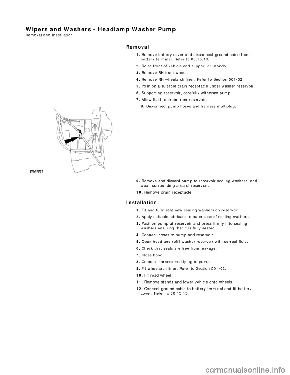
Wipers and Washers - Headlamp Washer Pump
Removal and Installation
Removal
Installation
1.
Remove battery cover and disc onnect ground cable from
battery terminal. Refer to 86.15.19.
2. Raise front of vehicle and support on stands.
3. Remove RH front wheel.
4. Remove RH wheelarch liner. Refer to Section 501-02.
5. Position a suitable drain recept acle under washer reservoir.
6. Supporting reservoir, ca refully withdraw pump.
7. Allow fluid to drain from reservoir.
8. Disconnect pump hoses and harness multiplug.
9. Remove and discard pump to re servoir sealing washers. and
clean surrounding area of reservoir.
10. Remove drain receptacle.
1. Fit and fully seat new sealing washers on reservoir.
2. Apply suitable lubricant to outer face of sealing washers.
3. Position pump at reservoir and press firmly into sealing
washers ensuring that it is fully seated.
4. Connect hoses to pump and reservoir.
5. Open hood and refill washer re servoir with correct fluid.
6. Check that seals are free from leakage.
7. Close hood.
8. Connect harness multiplug to pump.
9. Fit wheelarch liner. Refe r to Section 501-02.
10. Fit road wheel.
11. Remove stands and lowe r vehicle onto wheels.
12. Connect ground cable to batt ery terminal and fit battery
cover. Refer to 86.15.15.
Page 2314 of 2490
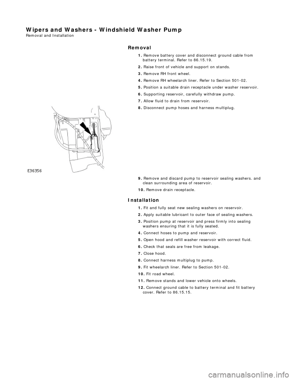
Wipers and Washers - Windshield Washer Pump
Removal and Installation
Removal
Installation
1.
Remove battery cover and disc onnect ground cable from
battery terminal. Refer to 86.15.19.
2. Raise front of vehicle and support on stands.
3. Remove RH front wheel.
4. Remove RH wheelarch liner. Refer to Section 501-02.
5. Position a suitable drain recept acle under washer reservoir.
6. Supporting reservoir, ca refully withdraw pump.
7. Allow fluid to drain from reservoir.
8. Disconnect pump hoses and harness multiplug.
9. Remove and discard pump to re servoir sealing washers. and
clean surrounding area of reservoir.
10. Remove drain receptacle.
1. Fit and fully seat new sealing washers on reservoir.
2. Apply suitable lubricant to outer face of sealing washers.
3. Position pump at reservoir and press firmly into sealing
washers ensuring that it is fully seated.
4. Connect hoses to pump and reservoir.
5. Open hood and refill washer re servoir with correct fluid.
6. Check that seals are free from leakage.
7. Close hood.
8. Connect harness multiplug to pump.
9. Fit wheelarch liner. Refe r to Section 501-02.
10. Fit road wheel.
11. Remove stands and lowe r vehicle onto wheels.
12. Connect ground cable to batt ery terminal and fit battery
cover. Refer to 86.15.15.
Page 2332 of 2490
Roof Opening Panel - Roof Opening Panel Frame
Removal and Installation
Removal
1. Adjust front passenger seat fu lly rearwards and fully recline
seat squab.
2. Remove battery cover and disc onnect ground cable from
battery terminal. Refer to 86.15.19.
3. Remove sliding roof flange finisher. Refer to 76.82.23.
4. Remove sliding roof trim panel. Refer to 76.82.19.
5. Remove grab handles. Refer to 501-05.
6. Remove roof console. Refer to 76.13.69.90.
7. Remove sun visors. Refer to 501-05.
8. Remove cantrail/upper A post trims. Refer to 76.13.20.
9. Remove rear quarter trim s. Refer to 76.13.13.
10. Remove front half headlining for access. refer to 76.64.15.90.
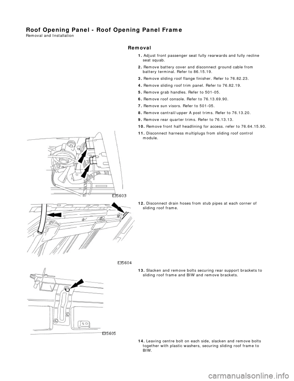
11. Disconnect harness multiplugs from sliding roof control
module.
12. Disconnect drain hoses from stub pipes at each corner of
sliding roof frame.
13. Slacken and remove bolts securi ng rear support brackets to
sliding roof frame and BIW and remove brackets.
14. Leaving centre bolt on each side, slacken and remove bolts
together with plastic washers, securing sliding roof frame to
BIW.
Page 2334 of 2490
tighten securing bolts.
7.
Align rear support brackets and tighten securing bolts.
8. Connect drain hoses to sliding roof frame stub pipes.
9. Fit headlining. Refer to 76.64.15.90.
10. Fit rear quarter trims. Refer to 76.13.13.
11. Fit cantrail/upper A post trims. Refer to 76.13.20.
12. Fit sun visors. Refer to 501-05.
13. Fit roof console. Refer to 76.13.69.90.
14. Fit grab handles. Refer to 501-05.
15. Fit sliding roof trim panel. Refer to 76.82.19.
16. Fit sliding roof flange fi nisher. Refer to 76.82.23.
17. Connect ground cable to batt ery terminal and fit battery
cover. Refer to 86.15.15.
18. Return front passen ger seat to original positions.
Page 2345 of 2490
bumper cover and remove both lamps from cover.
14. Release sidemarker lamp/refle ctor clips and remove both
lamps/reflectors from bumper cover.
15. Remove direction indicators fr om bumper assembly. Refer to
Section 417.01.
16. Remove powerwash jet assemb lies and hoses from top of
bumper assembly. Refer to Section 501-16.
17. Remove bumper blades.
1. Slacken and remove three screws securing each blade
to bumper cover.
2. Slide each blade forward to release two side tangs from cover and remove blade from bumper.
18. Rotate three splitter vane fasteners 1/4 turn counter-
clockwise and remove splitter vane from air intake.
19. Release tangs securing brake cooling ducts to cover and
remove ducts from bumper.
Page 2348 of 2490
1.
WARNING: ENSURE THAT ALL PERSONNEL AND
EQUIPMENT ARE CLEAR OF AREA BEFORE OPERATING RAMP.
Carefully slide bumper assembly onto fender guide blocks.
2. Raise ramp to working height.
3. Install but do not fully tighten bo lts securing bumper to struts.
4. Check clearance between top of bumper and bottom of fender.
If necessary, remove bumper, adjust guide blocks to achieve
correct clearance and refit bumper.
5. Connect harness multiplugs to foglamps, direction indicators
and where fitted side marker lamps.
6. Install harnesses in retaining clips at each side of cover.
7. Install powerwash hoses to jet assemblies and secure with new
plastic clips. Refer to Section 501.16.
8. Install radiator grill and su rround. refer to 76.55.03 and
76.55.15.
9. Check and as necessary adjust bumper cover to fender,
headlamps and radiator grill surround clearances. Refer to
Description and Operation in this section.
10. Fully tighten bumper assembly to strut securing bolts.
11. Install wheelarch liners.
12. Install undertray. Refer to 76.22.90.
13. Lower 4-post ramp.
14. Install road wheels and lower wheel-free lifts.
Page 2350 of 2490
13. Release sidemarker lamp/refle ctor clips and remove both
lamps/reflectors from bumper cover.
14. Remove direction indicators fr om bumper assembly. Refer to
Section 417.
15. Release tangs securing brake cooling ducts to bumper cover
and remove ducts.
16. Remove powerwash jet assemb lies and hoses from top of
bumper assembly. Refer to 84.20.08.
17. Remove bumper blades.
1. Remove three screws secu ring each blade to bumper
cover.
2. Slide each blade forward to release two side tangs from cover and remove blades from bumper.
18. Rotate three splitter vane fasteners 1/4 turn counter-
clockwise and remove splitter vane from air intake.
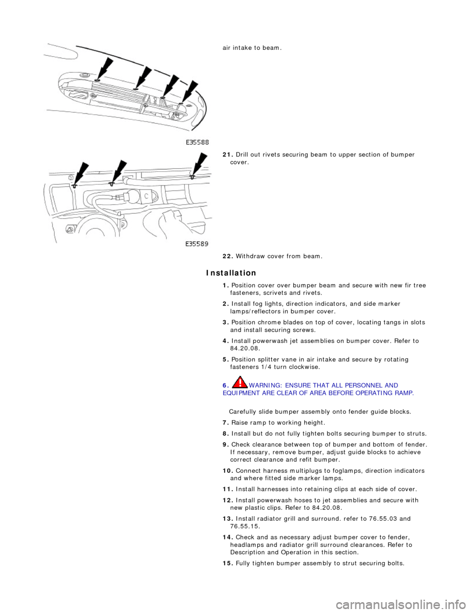
19. Remove number plate and plinth.
20. Remove and discard four scrive ts securing upper section of
Page 2351 of 2490
Installation
air intake to beam.
21. Drill out rivets securing beam to upper section of bumper
cover.
22. Withdraw cover from beam.
1. Position cover over bumper beam and secure with new fir tree
fasteners, scrivets and rivets.
2. Install fog lights, direction indicators, and side marker
lamps/reflectors in bumper cover.
3. Position chrome blades on top of cover, locating tangs in slots
and install securing screws.
4. Install powerwash jet assemblies on bumper cover. Refer to
84.20.08.
5. Position splitter vane in air intake and secure by rotating
fasteners 1/4 turn clockwise.
6. WARNING: ENSURE THAT ALL PERSONNEL AND
EQUIPMENT ARE CLEAR OF AREA BEFORE OPERATING RAMP.
Carefully slide bumper assembly onto fender guide blocks.
7. Raise ramp to working height.
8. Install but do not fully tighten bo lts securing bumper to struts.
9. Check clearance between top of bumper and bottom of fender.
If necessary, remove bumper, adjust guide blocks to achieve
correct clearance and refit bumper.
10. Connect harness multiplugs to foglamps, direction indicators
and where fitted side marker lamps.
11. Install harnesses into retaining clips at each side of cover.
12. Install powerwash hoses to jet assemblies and secure with
new plastic clips. Refer to 84.20.08.
13. Install radiator grill and su rround. refer to 76.55.03 and
76.55.15.
14. Check and as necessary adjust bumper cover to fender,
headlamps and radiator grill surround clearances. Refer to
Description and Operation in this section.
15. Fully tighten bumper assembly to strut securing bolts.