1998 JAGUAR X308 AF sensors
[x] Cancel search: AF sensorsPage 1802 of 2490
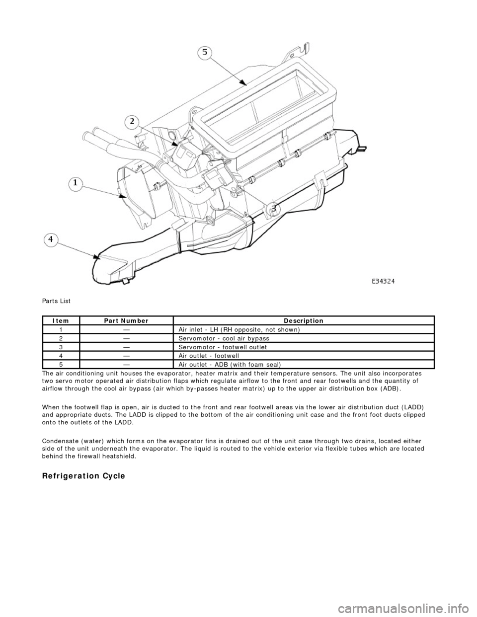
Parts List
The air conditioning unit houses the evap orator, heater matrix and their temperatur e sensors. The unit also incorporates
two servo motor operated air distribution flaps which regulate airflow to the front and rear footwells and the quantity of
airflow through the cool air bypass (air which by-passes he ater matrix) up to the upper air distribution box (ADB).
When the footwell flap is open, air is du cted to the front and rear footwell areas via the lower air distribution duct (LADD)
and appropriate ducts. The LADD is clipped to the bottom of the air conditioning unit case an d the front foot ducts clipped
onto the outlets of the LADD.
Condensate (water) which forms on the evaporator fins is drained out of the unit case through two drains, located either
side of the unit underneath the evaporator. The liquid is routed to the vehicle exterior via flexible tubes which are located
behind the firewa ll heatshield.
Refrigeration Cycle
ItemPart NumberDescription
1—Air inlet - LH (RH opposite, not shown)
2—Servomotor - cool air bypass
3—Servomotor - footwell outlet
4—Air outlet - footwell
5—Air outlet - ADB (with foam seal)
Page 1827 of 2490
Maximum Cooling (temperature setting LO)
Air Conditioning Control Module (A/CCM)
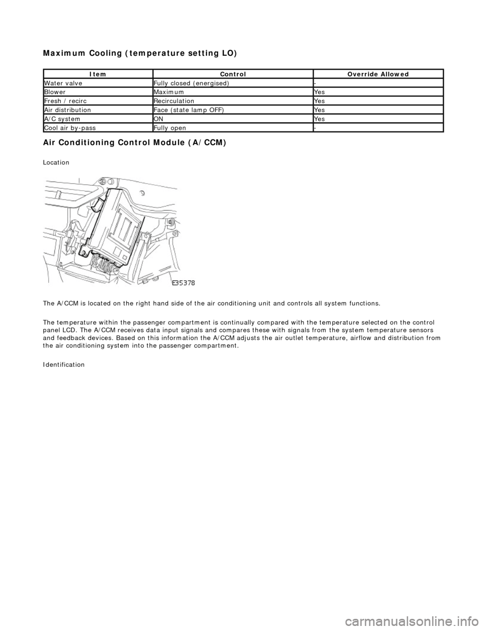
Location
The A/CCM is located on the right hand side of the air conditioning unit and controls all system functions.
The temperature within the passenger compartment is continually compared with the temperature selected on the control
panel LCD. The A/CCM receives data input signals and compares these with signal s from the system temperature sensors
and feedback devices. Based on this information the A/CCM adjusts the air outlet temperatur e, airflow and distribution from
the air conditioning system in to the passenger compartment.
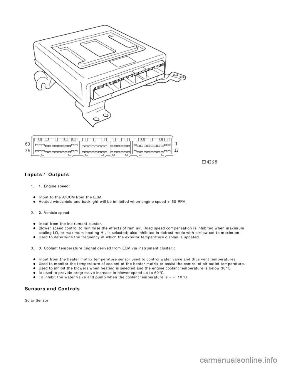
Identification
ItemControlOverride Allowed
Water valveFully closed (energised)-
BlowerMaximumYes
Fresh / recircRecirculationYes
Air distributionFace (state lamp OFF)Yes
A/C systemONYes
Cool air by-passFully open-
Page 1828 of 2490
Inputs / Outputs
1.1. Engine speed:
Input to the A/CCM from the ECM. Heated windshield and backli ght will be inhibited when engine speed < 50 RPM.
2. 2. Vehicle speed:
Input from the instru ment cluster. Blower speed control to minimise the effects of ram ai r. Road speed compensation is inhibited when maximum
cooling LO, or maximum heating HI, is selected; also inhi bited in defrost mode with airflow set to maximum.
Used to determine the frequency at which the exterior temperature display is updated.
3. 3. Coolant temperature (signal derived from ECM via instrument cluster):
Input from the heater matrix temperature sensor used to control water valve and thus vent temperatures. Used to monitor the temperature of coolant at the heater matrix to assist the control of air outlet temperature. Used to inhibit the blowers when heating is selected and the engine coolant temperature is below 30°C. Is used to provide progressive increase in blower speed up to 60°C. To inhibit the water valve and pump when the coolant temperature is = < 10°C
Sensors and Controls
Solar Sensor
Page 1831 of 2490
other sensors. This feature prevents the effects of sudden changes in air outlet temperatures due to factors such as:
Recirculating air from the engine cooling pack at low vehicle speeds Sudden changes in ambient temperature The effects of water splash
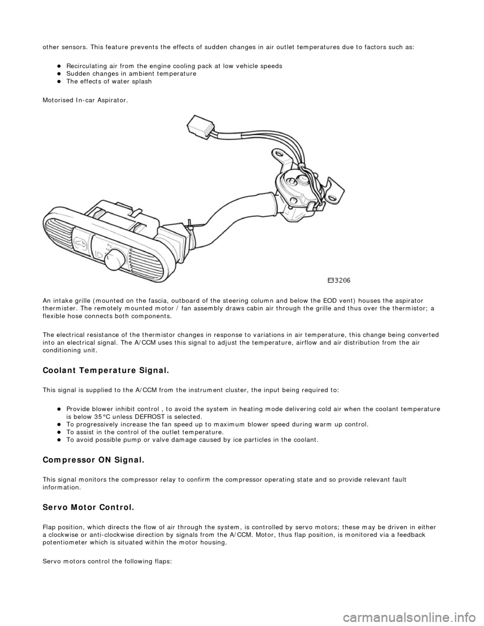
Motorised In-car Aspirator.
An intake grille (mounted on the fascia , outboard of the steering column and below the EOD vent) houses the aspirator
thermister. The remotely mounted motor / fan assembly draws ca bin air through the grille and thus over the thermistor; a
flexible hose connects both components.
The electrical resistance of the thermistor changes in response to variations in air temperatur e, this change being converted
into an electrical signal. The A/CCM uses this signal to adjust the temperature, airflow and air distribution from the air
conditioning unit.
Coolant Temperature Signal.
This signal is supplied to the A/CCM from the instrument cluster, the input being required to:
Provide blower inhibit control , to avoid the system in heat ing mode delivering cold air when the coolant temperature is below 35°C unless DEFROST is selected. To progressively increase the fan speed up to maximum blower speed during warm up control. To assist in the control of the outlet temperature. To avoid possible pump or valve damage ca used by ice particles in the coolant.
Compressor ON Signal.
This signal monitors the compressor relay to confirm the compressor operating state and so provide relevant fault
information.
Servo Motor Control.
Flap position, which directs the flow of air through the system, is controlled by servo motors; these may be driven in either
a clockwise or anti-clockwise direction by signals from the A/ CCM. Motor, thus flap position, is monitored via a feedback
potentiometer which is situated within the motor housing.
Servo motors control the following flaps:
Page 1835 of 2490
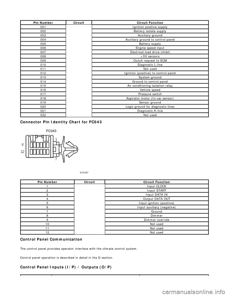
Connector Pin Identity Chart for FC043
Control Panel Communication
The control panel provides operator interface with the climate control system.
Control panel operation is described in detail in the D section.
Control Panel Inputs (I/P) / Outputs (O/P)
Pin NumberCircuitCircuit Function
001Ignition positive supply
002Battery isolate supply
003Auxiliary ground
004Auxiliary ground to control panel
005Battery supply
006Engine speed input
007Electrical load drive inhibit
008+5V sensors
009Clutch request to ECM
010Diagnostic L-line
011Not used
012Ignition (positive) to control panel
013System ground
014Ground to control panel
015Air conditioning isolation relay
016Vehicle speed
017Pressure switch
018Aspirator motor (In-car sensor)
019Sensor ground
020Logic ground for diagnostic lines
021Diagnostic K-line
022Not used
Pin NumberCircuitCircuit Function
1Input CLOCK
2Input START
3Input DATA IN
4Output DATA OUT
5Input ignition (positive)
6Input auxiliary (negative)
7Ground
8Dimmer
9Dimmer override
10Not used
11Not used
12Not used
Page 1837 of 2490
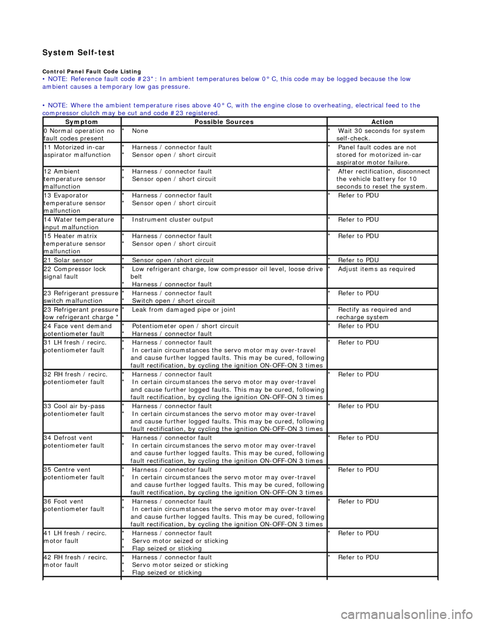
System Self-test
Control Panel Fault Code Listing • NOTE: Reference fault code #23*: In ambient temperatures below 0° C, this code may be logged because the low
ambient causes a tempor ary low gas pressure.
• NOTE: Where the ambient temperature rises above 40° C, with the engine close to overheating, electrical feed to the
compressor clutch may be cut and code #23 registered.
SymptomPossible SourcesAction
0 Normal operation no
fault codes presentNone
*Wait 30 seconds for system
self-check.
*
11 Motorized in-car
aspirator malfunctionHarness / connector fault
Sensor open / short circuit
*
*Panel fault codes are not
stored for motorized in-car
aspirator motor failure.
*
12 Ambient
temperature sensor
malfunctionHarness / connector fault
Sensor open / short circuit
*
*After rectification, disconnect
the vehicle battery for 10
seconds to reset the system.
*
13 Evaporator
temperature sensor
malfunctionHarness / connector fault
Sensor open / short circuit
*
*Refer to PDU
*
14 Water temperature
input malfunctionInstrument cl uster output
*Refer to PDU
*
15 Heater matrix
temperature sensor
malfunctionHarness / connector fault
Sensor open / short circuit
*
*Refer to PDU
*
21 Solar sensorSensor open /short circuit
*Refer to PDU
*
22 Compressor lock
signal faultLow refrigerant charge, low compressor oil level, loose drive
belt Harness / connector fault
*
*Adjust items as required
*
23 Refrigerant pressure
switch malfunctionHarness / connector fault
Switch open / short circuit
*
*Refer to PDU
*
23 Refrigerant pressure
low refrigerant charge * Leak from damaged pipe or joint
*Rectify as required and
recharge system
*
24 Face vent demand
potentiometer faultPotentiometer open / short circuit
Harness / connector fault
*
*Refer to PDU
*
31 LH fresh / recirc.
potentiometer faultHarness / connector fault
In certain circumstances the servo motor may over-travel
and cause further logged faults. This may be cured, following
fault rectification, by cycling the ignition ON-OFF-ON 3 times
*
*Refer to PDU
*
32 RH fresh / recirc.
potentiometer faultHarness / connector fault
In certain circumstances the servo motor may over-travel
and cause further logged faults. This may be cured, following
fault rectification, by cycling the ignition ON-OFF-ON 3 times
*
*Refer to PDU
*
33 Cool air by-pass
potentiometer faultHarness / connector fault
In certain circumstances the servo motor may over-travel
and cause further logged faults. This may be cured, following
fault rectification, by cycling the ignition ON-OFF-ON 3 times
*
*Refer to PDU
*
34 Defrost vent
potentiometer faultHarness / connector fault
In certain circumstances the servo motor may over-travel
and cause further logged faults. This may be cured, following
fault rectification, by cycling the ignition ON-OFF-ON 3 times
*
*Refer to PDU
*
35 Centre vent
potentiometer faultHarness / connector fault
In certain circumstances the servo motor may over-travel
and cause further logged faults. This may be cured, following
fault rectification, by cycling the ignition ON-OFF-ON 3 times
*
*Refer to PDU
*
36 Foot vent
potentiometer faultHarness / connector fault
In certain circumstances the servo motor may over-travel
and cause further logged faults. This may be cured, following
fault rectification, by cycling the ignition ON-OFF-ON 3 times
*
*Refer to PDU
*
41 LH fresh / recirc.
motor faultHarness / connector fault
Servo motor seized or sticking
Flap seized or sticking
*
*
*Refer to PDU
*
42 RH fresh / recirc.
motor faultHarness / connector fault
Servo motor seized or sticking
Flap seized or sticking
*
*
*Refer to PDU
*
Page 1856 of 2490
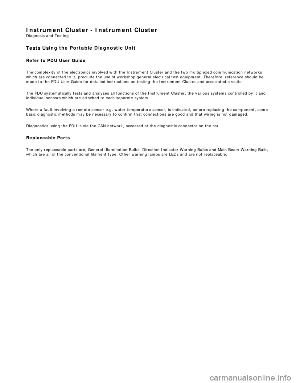
Instrument Cluster - Ins
trument Cluster
D
iagn
osis and Testing
Tests U
s
ing the Portable Diagnostic Unit
Re
fe
r to PDU User Guide
The c
o
mplexity of the electronics involved with the Instrument Cluster and the two multiplexed communication networks
which are connected to it, preclude the use of workshop genera l electrical test equipment. Therefore, reference should be
made to the PDU User Guide for detailed instructions on testing the Instrument Clus ter and associated circuits.
The PDU systematically test s and analyses all functions of the Instrument Clus ter, the various systems controlled by it and
individual sensors which are attached to each separate system.
Where a fault involving a remote sensor e. g. water temperature sensor, is indicated, before replacing the component, some
basic diagnostic methods may be necessary to confirm that connections are good and that wiring is not damaged.
Diagnostics using the PDU is via the CAN network, accessed at the diagnostic connector on the car.
Replaceable Parts
The only replaceable part s
are, General Illumination Bulbs, Direction Indicator Warning Bu
lbs and Main Beam Warning Bulb,
which are all of the conventional filament type. Other warning lamps are LEDs and are not replaceable.
Page 1869 of 2490
The functi
on of the parking aid is to prov
ide an audible warning to the driver of the distance to obstacles near the rear
bumper of the vehicle when parking or travelling at a slow sp eed. The system provides an assistance to the driver when
parking in order to help avoid collision with obstacles.
The sensor range at the rear of the vehicl e should be 1.8 meters. This should extend the full width of the rear bumper and
reduce to 50 cm at the vehicle co rners. The vertical range is adequate to protec t the highest and lowest points of the rear of
the vehicle. The system will detect curbs with heights of at least 18 cm. Obstacles, such as curbs, that are low enough to
pass under the vehicle until they make contact with the tires will not be detected.
The system activates a specific speaker with a tone signifying the distance to the obstacle. The tone consists of a beep and
defined space ratio which varies depending on the calculated distance. When the distance to the obstacle is less than 20 cm
the speaker tone is continuous.
The parking aid is continuously in operation, unless towing wh en the system automatically switches off. If the reverse aid
develops a fault the tone will sound continuously for three seconds when the igni tion is switched on or the reverse gear is
selected.
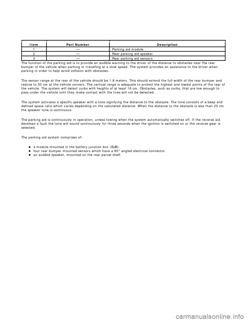
The parking aid system comprises of:
a
module mounted in the batte
ry junction box (BJB).
fou
r rear bumper mounted sensors which have a 90° angled electrical connector.
an audible speaker, moun
ted on
the rear parcel shelf.
It
em
Par
t Number
De
scription
1—Parkin
g aid module
2—Rear
parking aid speaker
3—Rear
parking aid sensors