Page 1110 of 2490

2.2. Cruise
3. 3. Mechanica l
guard
4. 4. Fixed idle
5. 5. Redundancy
6. 6. Full authority
7. 7. Engine shut-down
Normal mode occurs when the EC M uses the mechanical and monitoring arrangem ent of the throttle valve to control throttle
opening. The ECM does not permit driver demand to be exceeded but it can be restricted to allow for such features as
stability / traction control, or engine power limitation.
The ECM determines engine idle speed by controlling the throttle valve motor to vary the blade angle between the non-
adjustable preset limits of the mechanic al guard and the throttle valve motor.
Cruise mode is engaged as a result of the ECM calculating and controlling the required throttle valve opening via the
vacuum system. When the driver releases the throttle pedal, the input shaft disengages from the mechanical guard or the
vacuum actuator pulls the guard away from th e throttle valve. The throttle pedal will feel light should it be pushed again to
accelerate (pressing the pedal further will re-engage the input shaft with the mechanical guard and restore normal feel).
The ECM utilizes sensors to monitor the relative positions of the mechanical guard and throttle valve and adjusts them to
maintain the set cruise speed.
Mechanical guard mode permits full mechanical operation of the throttle if the ECM detects that a problem has been
encountered with the throttle valve position sensor, dc motor, associated harnesses / connecto rs or the ECM.
Fixed idle mode occurs when any two of the three sensors (two input shaft sensors and the mechanical guard sensor) fail.
The ECM will assume values which represent a blade angl e of approximately 2,5° and 1200 rpm (unloaded) maximum
engine speed.
Redundancy mode occurs when any one of the three sensors (two input shaft sensors and the mechanical guard sensor)
fails. The operational pair will be deemed to be safe to co ntinue without intervention, but cruise will be inhibited.
Full authority mode is invoked when a mech anical guard failure occurs which indicates that the guard is stuck fully open.
The red warning lamp will be lit and road speed will be li mited to 120 kph.
Engine shut-down mode will occur followin g multiple failures, such as mechanical guard mode following full authority mode
(or vice versa) or the throttle blade sticks.
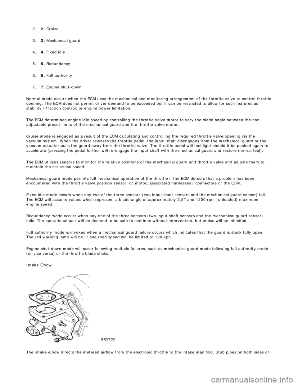
Intake Elbow
The intake elbow directs the metered airflow from the electronic throttle to the intake manifold. Stub pipes on both sides of
Page 1149 of 2490

The E
VAP canister purge valve controls th
e flow rate of fuel vapour drawn into the engine during the canister purge
operation. The valve is opened by a vacu um feed from the induction elbow : the vacu um feed is controlled by the integral
valve solenoid and is applied when the so lenoid is energised. The solenoid is pulsed on (energised) and off by a fixed
frequency (100Hz) variable pulse width control signal (pulse width modulation). By varying the pulse on to off time, the
ECM controls the duty cycle of the valve (time that the valve is open to time closed) and thus the vapour flow rate to the
engine.
With no ECM signal applied to the va lve solenoid, the valve remains closed.
Can
ister Purge Operation
The
following pre-conditions are ne
cessary for purging to commence :
aft
er battery disconnection/reconnection, engine
management adaptations must be re-instated.
engine has run for
at least 8 seconds.
engi
ne coolant temperature is not less than 70 °C.
engine
not running in the fuel
cut off condition (eg overrun).
t
he adaptive fuel correction
function has not registered a rich or lean failure
t
he evaporative emission leak test has not failed
no faults have been diagnosted in th
e rel
evant sensor and valve circuits -
Air Flow Meter (AFM), Engine Coolant
Temperature sensor, Evaporativ e Canister Purge valve and Canister Close Valve (CCV).
If these conditions have been satisfied, purging is started. If any failures are registered, purging is inhibited.
The canister(s) is purged during each driv e cycle at various rates in accordance with the prevailing engine conditions. The
engine management software st ores a map of engine speed (RPM) against engine load (grams of air inducted / rev). For
any given engine speed and load, a vapour purge rate is assigned (purge rate increases with engine speed and load).
The preset purge rates are base d on the assumption of a vapour concentratio n of 100%. The actual amount of vapour is
measured by the closed loop fueling system : the input of evaporative fuel into the engine causes the outputs from the
upstream oxygen sensors to change, the am ount of change providing a measure of the vapour concentration. This feedback
causes the original purge rate to be adju sted and also reduces the amount of fuel input via the injectors to maintain the
correct air to fuel ratio.
Engine speed/load mapping and the corresp onding purge rates are different for single canister, running loss and ORVR
evaporative systems.
Page 1177 of 2490

Th
e engine management system provides optimum control of
the engine under all operating conditions using several
strategically placed sensors and any necessary actuators. Electronic engine control consists of:
engine
control module
throttle posi
tion sensor
engi
ne coolant temperature sensor
cam
shaft position sensor
c
rankshaft position sensor
mass air
flow sensor
intake air temper
ature sensor
kn
ock sensor
heat
ed oxygen sensor
Electronic Engine Control
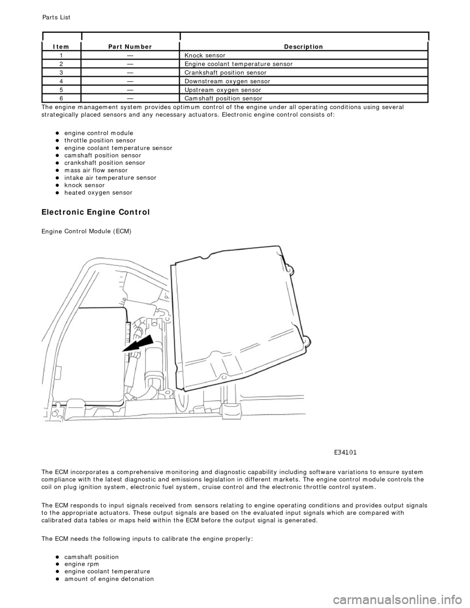
Engine
Control Module (ECM)
The ECM incorporates a comprehensive monitoring and diagnostic capability including software variations to ensure system
compliance with the latest diagnostic and emissions legislation in different markets. The engine control module controls the
coil on plug ignition system, electronic fuel system, cr uise control and the electronic throttle control system.
The ECM responds to input signals received from sensors relating to engine operatin g conditions and provides output signals
to the appropriate actuators. These outp ut signals are based on the evaluated input signals which are compared with
calibrated data tables or maps held within th e ECM before the output signal is generated.
The ECM needs the following inputs to calibrate the engine properly:
cam
shaft position
It
em
Par
t Number
De
scription
1—Knock
sensor
2—Engine
coolant temperature sensor
3—Cranksh
aft position sensor
4—D
ownstream oxygen sensor
5—Upstream oxygen sensor
6—Camshaft position
sensor
P
arts List
engi
ne rpm
engi
ne coolant temperature
amount
of engine detonation
Page 1178 of 2490
Throttle Position (TP) Sensor
Location
P
arts List
sen
d
s the ECM a signal indica
ting throttle plate angle
is
the main input to the ECM from the driver
i
s
a dual Hall effect devi
ce mounted on the motor en d of the throttle body
Two additional sensors are attached to the throttle body to provide additional feedback to the ECM: a mechanical guard
position sensor and an accelerator pedal position sensor.
Cam s
haft Position (CMP) Sensor
sen
d
s the ECM a signal indicating camshaft po
sition for fuel synchronization purposes
is
a variable reluctance device mounted on bank 2 cylinder side face
generates a signal when the ri
ng
fitted to the bank 2 inlet
camshaft passes the sensor
Cranksha
ft Position (CKP) Sensor
i
s
a variable reluctance device
mounted on the engine oil pan
Ite
m
Par
t
Number
De
scr
iption
1—Acce
le
rator pedal and mechanic
al guard position sensors
2—Throttle
(blade)
position sensor
Page 1179 of 2490

generates a signal when th
e dr
ive plate passes the sensor
sen
ds the ECM signals indicating crankshaft position and engine speed
is e
ssential for calculating spark timing
En
gine Coolant Temperature (ECT) Sensor
sen
ds the ECM a signal indicating the temperature of the engine coolant
is a t
emperature dependent resistor with a negative temperature coefficient (resistance changes inversely with
respect to temperature) and is constantly monitored by the ECM
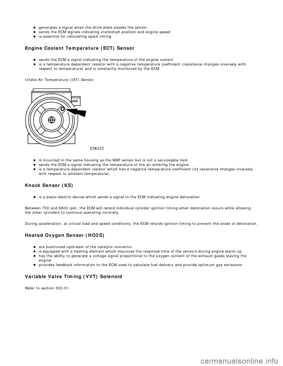
Intake Air Temperature (IAT) Sensor
is m
ounted in the same housing as the MA
F sensor but is not a serviceable item
sen
ds the ECM a signal indicating the temperature of the air entering the engine
is a t
emperature dependent resistor which has a negative
temperature coefficient (its resistance changes inversely
with respect to ambient temperature).
Knock S
ensor (KS)
is a pi
ezo-electric device which sends a signal
to the ECM indicating engine detonation
Between 700 and 6800 rpm, the ECM will retard individual cylinder ignition timing when detonation occurs while allowing
the other cylinders to continue operating normally.
During acceleration, at critical load and speed conditions, the ECM retards ignition timing to prevent the onset of detonation.
H
eated Oxygen Sensor (HO2S)
are
positioned upstream of the catalytic convertor
is equipped with
a heating element wh
ich improves the response time of the sensors during engine warm-up
h
as the ability to generate a voltage signal proportional to the oxygen content of the exhaust gases leaving the
engine
pr
ovides feedback information to the ECM used to calc
ulate fuel delivery and provide optimum gas emissions
Variable V
alve Timing (VVT) Solenoid
R
efer to section 303-01.
Page 1181 of 2490
P
arts List
It
em
Par
t Number
De
scription
1—PI032
VVT solenoid 2
2—PI027
KS 2
3—PI004
ECT sensor
4—PI026
KS 1
5—PI031
VVT solenoid 1
6—PI035
MAFS (on vehicle)
7—PI050
Generator
8—PI040
Oil pressure switch
9—PI018
to PI021 Bank 1 Ignition coils 1 to 4
PI022 to PI025 Bank 2 Ignition coils 1 to 4
10—PI006
Throttle valve position sensor
11—PI002 En
gine management harness (on vehicle)
12—PI001 En
gine management harness (on vehicle)
13—PI033
Throttle valve motor
14—PI034
EGR valve (where fitted)
15—PI015 CM
P sensor
16—PI042
Accelerator pedal and
mechanical guard sensors
17—PI007
to PI010 Bank 1 Injectors 1 to 4 PI011 to PI014 Bank 2 Injectors 1 to 4
18—PI037
Compressor lock
sensor (where fitted)
19—PI036
Compressor clutch
20—PI017 CK
P sensor
E
ngine Harness Connectors
Location
Page 1183 of 2490
It
em
De
scription
1Mechanica
l guard
position sensor (potentiometer)
2Pedal demand sensors (pot
entiometers)
3Thro
ttle position sensor
4Engine
control
module (ECM)
5Throttl
e motor power relay
6EMS fuse box
7Throttl
e motor
T
hrottle Sensors and Control
Page 1184 of 2490
Ite
m
Part
Number
Descr
iption
1—Knock
sensors, banks 1 and 2
2—Engine
control module (E
CM)
Knock
Sensor