Page 1989 of 2490

Wiring Harnesses - Wiring Harness
Description and Operation
Introduction
CAUTION: Do not use any other heat shrink sleeve other than the approved glue lined heat shrink sleeve mentioned
in the repair procedure.
The purpose of this document is to promote quick and efficient minor repair to harness connectors or cables using approved
methods and the wiring harness repair kit. Repairs may only be made to cables and connectors which have been
mechanically, not electrically damaged. It also applies wher e the whole extent of the damage can be clearly identified and
rectified.
Care and neatness are essential requir ements in making a perfect repair.
Caution:
At the time of this first issue of the Harness Repair Guide, do not approve re pairs to any of the following circuits:
Any media orientated system transport network harnesses. Supplement restraint system (SRS) firing circuits (Air bags). Link lead assembles, which are unique to safety critical circuits such as anti-lock brake system (ABS) and
thermocouple circuits. An example of this is the ABS wheel speed sensors with moulded connectors.
4. Screened cables, leads and wiring harness(s).
If any harness(s) with defective electrical connector te rminals or wires from the above circuits are a concern,
new components must be installed.
Repair Kit
CAUTION: Where the repair procedure indica tes that a glue lined heat shrink sleeve should be applied, apply sufficient
heat to the glue lined heat shrink to melt the glue in order to provide a water tight seal. Do not over heat the glue lined
heat shrink sleeve so that the wiring harness insulation becomes damaged.
The wiring harness repair kit has been produced which comprises:
Pre-terminated wiring harness(s) of different sizes and types Three sizes of butt splice connectors A selection of colored cable identification sleeves Two sizes of glue lined heat shrink sleeves Crimping pliers A wire cutter and insulation stripper An electrical connector terminal extraction handle and tips
A suitable heat source, fo r shrinking heat shrink sleeves will be required.
The pre-insulated diamond grip range of el ectrical connector terminals and in-line, butt splice connectors contained within
the wiring harness repair kit are the only acceptable product for the repairs of wi ring harnesses. The butt connectors not
only grip the wire but also the insu lation, making a very secure joint.
If an electrical connector terminal is not included in the wiring harness repair kit then approval for the repair is NOT given
and in these circumstances a new wi ring harness must be installed.
Pre-Terminated Wiring Harness( s) and Butt Splice Connectors
All pre-terminated wiring harness(s) and butt splice connectors in the wiring harness repair kit are contained in bags which
can be resealed after use. Each bag is marked with the part number of the items stored within the bag. Each storage
compartment in the wiring harness repair kit is identified with the corresponding part number. Make sure that pre-
terminated wiring harness(s) and connectors are not mixed up it is advisable to only open one bag at a time and to reseal
Page 2077 of 2490
Installation
All vehicles
Remove the retaining screw.
10. With the aid of another tech nician, lower the headliner.
11. With the aid of another techni cian, remove the headliner.
12. NOTE: Left-hand shown, right-hand similar.
Detach the anti-theft sensors.
13. NOTE: Left-hand shown, right-hand similar.
Remove the anti-t heft sensors.
1. Disconnect the electrical connector.
1. NOTE: Left-hand shown, right-hand similar.
Page 2078 of 2490
Install the anti-theft sensors. 1. Connect the electrical connector.
2. NOTE: Left-hand shown, right-hand similar.
Attach the anti-theft sensors.
3. CAUTION: With the aid of an other technician, support the
headliner.
Install the headliner.
4. With the aid of another tech nician, raise the headliner.
5. CAUTION: Support the headliner to ensure it is not folded or creased during installation.
• NOTE: Left-hand shown, right-hand similar.
Install the headliner retaining trims.
Install the retaining screw.
6. NOTE: Left-hand shown, right-hand similar.
Attach the screw cover.
Page 2361 of 2490

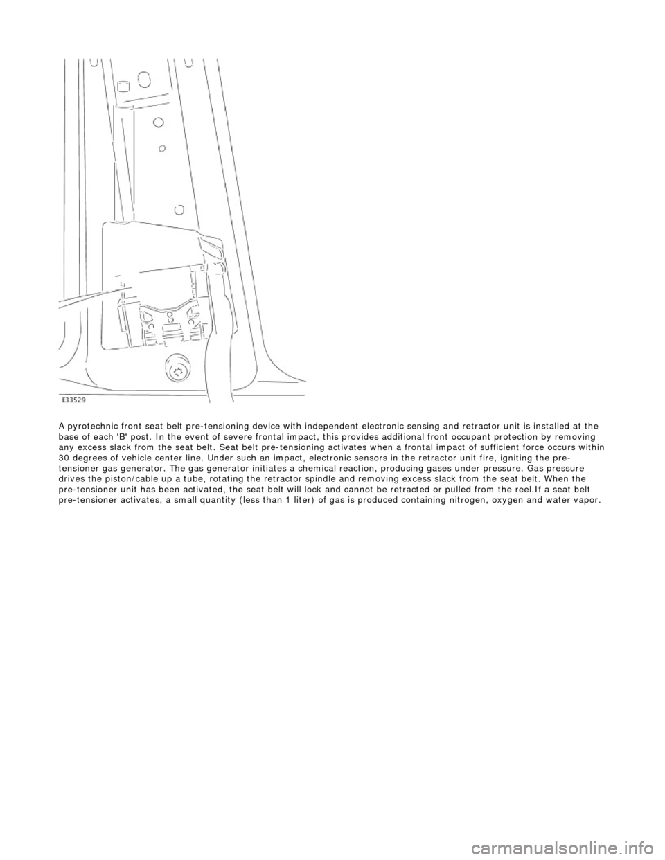
A pyrotechnic front seat belt pre-tensioning device with independent el ectronic sensing and retractor unit is installed at the
base of each 'B' post. In the event of se vere frontal impact, this provides additional front occupant protection by removing
any excess slack from the seat be lt. Seat belt pre-tensioning activates when a frontal impact of sufficient force occurs within
30 degrees of vehicle center line. Under such an impact, el ectronic sensors in the retractor unit fire, igniting the pre-
tensioner gas generator. The ga s generator initiates a chemical reaction, producing gases under pressure. Gas pressure
drives the piston/cable up a tube, rotating the retractor sp indle and removing excess slack from the seat belt. When the
pre-tensioner unit has been activated, the seat belt will lock and cannot be retracted or pulled from the reel.If a seat belt
pre-tensioner activates, a small quantity (less than 1 liter) of gas is produced containing nitrogen, oxygen and water vapor.