Page 1010 of 2490
Re
move the drive belt from the generator and accessory drive.
1. Use a spanner e.g. Churchill JD-230 or Snap On XDHM 1415, on the centre bolt of the belt tensioner idler pulley, to turn the adjuster assembly to the left against spring tension.
2. Whilst holding the tensioner against spring tension, remove the drive belt from the generator pulley. Release the tensioner slowly and remove the spanner.
Disconnect the belt from the other pulleys, as necessary, to move it clear of the pump pulley.
5.
Remove the pulley from the water pump.
1. remove the pulley securing screws.
2. Remove the pulley from the water pump.
Clean relevant parts and faces.
Installation
1.
Installation is the reverse of the removal procedure. Tighten the pulley securing bolts to 10-14 Nm.
Page 1049 of 2490

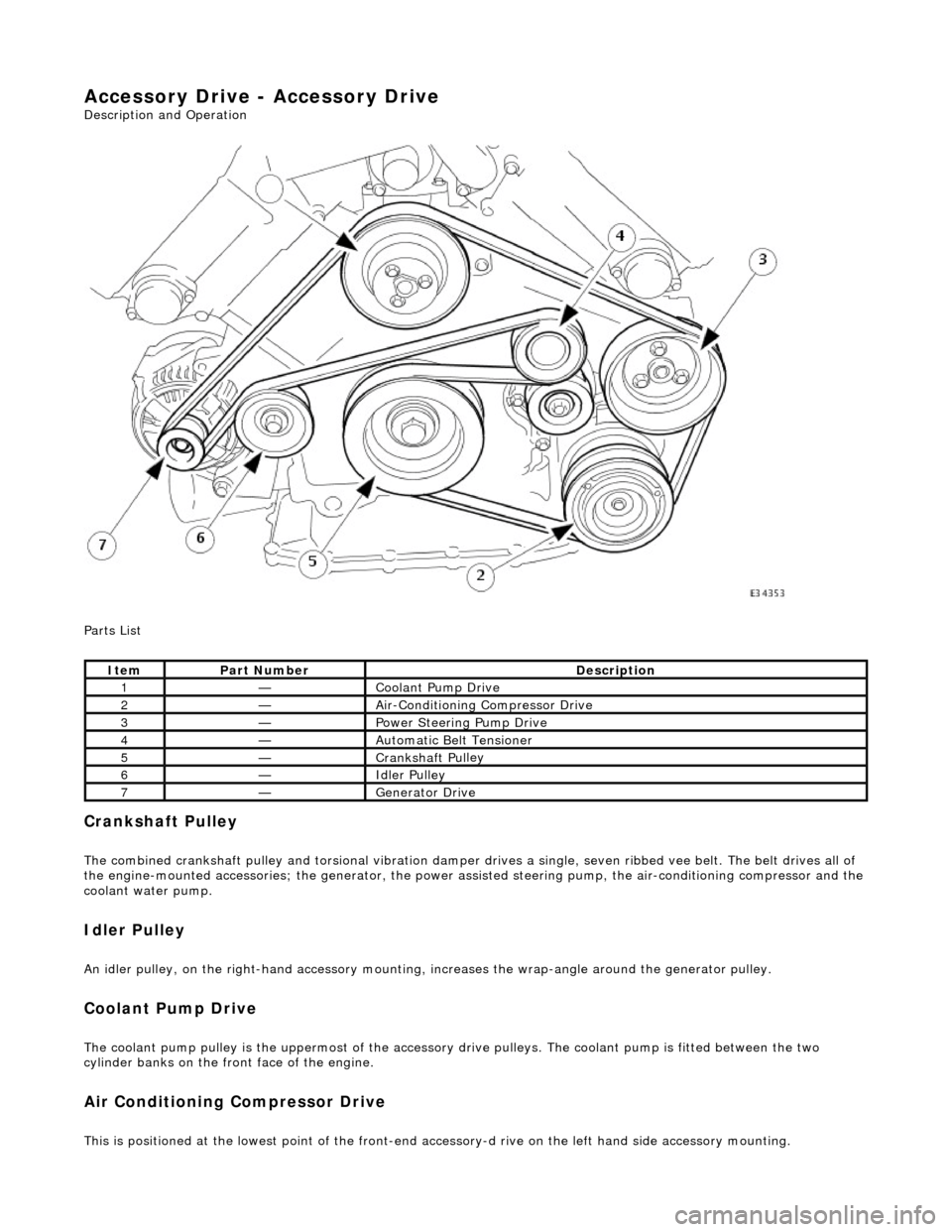
Accessory Drive - Accessory Drive
Description an
d Operation
Parts List
Cran
kshaft Pulley
The combined crankshaft
pulley and torsio
nal vibration damper drives a single, seve n ribbed vee belt. The belt drives all of
the engine-mounted accessories; the generator, the power assi sted steering pump, the air-conditioning compressor and the
coolant water pump.
I
dler Pulley
An i
dler pulley, on the right-hand
accessory mounting, increases the wrap-angle around the generator pulley.
Coolant Pump Drive
The coolan
t pump pulley is the
uppermost of the accessory drive pulleys. Th e coolant pump is fitted between the two
cylinder banks on the front face of the engine.
Air Conditioning Compressor Drive
Thi
s is positioned at the lowest poin
t of the front-end accessory-d rive on the left hand side accessory mounting.
It
em
Par
t Number
De
scription
1—Coo
lant Pump Drive
2—Ai
r-Conditioning Compressor Drive
3—Power Steer
ing Pump Drive
4—Au
tomatic Belt Tensioner
5—Crankshaft Pul
ley
6—Idle
r Pulley
7—Generator Dri
ve
Page 1050 of 2490
Power Assisted Steering Pump Drive
The power assisted steering pump pull
ey
is located on the left side, above the air-conditioning compressor.
Generator Dr
ive
The genera
tor is fitted on the
right hand accessory mounting.
Drive Belt
The drive belt should be inspected at every routine service for excessive wear and damage. A drive belt which displays
symptoms of cracking may be pe rfectly fit for further service.
Should cracking be detected, serviceability ma y be assessed using the following guidelines:
Fi
fteen cracks per rib over a 100 mm le
ngth of drive belt is acceptable.
Sec
tion(s) of belt missing from an
y rib is not acceptable and the drive belt must be renewed.
Ite
m
De
scr
iption
1Ac
c
eptable Drive Belt Cracking
2Unacceptable Drive Belt Damage
Page 1052 of 2490

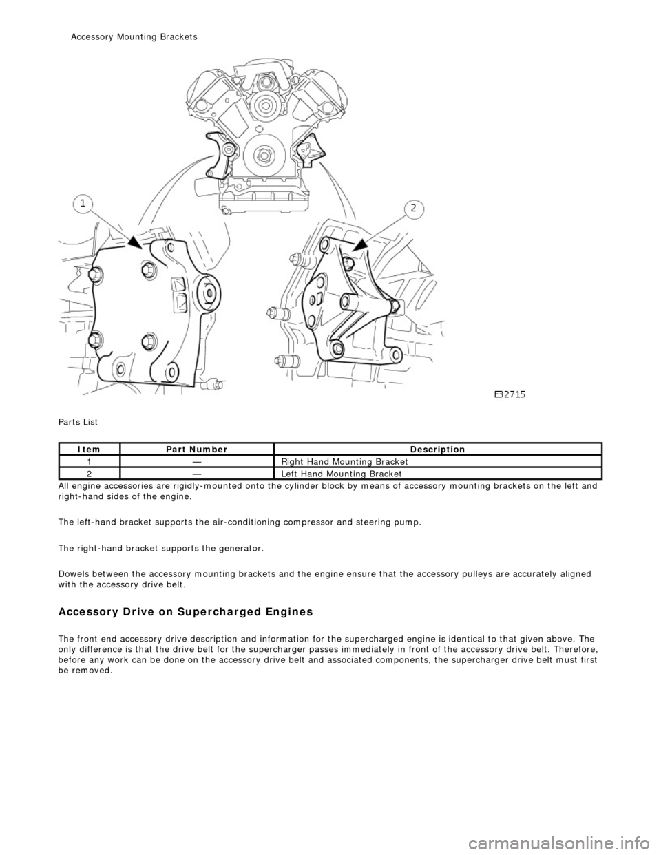
P a
rts List
All engine accessories are rigidly-mounted onto the cylinder block by means of accessory moun ting brackets on the left and
right-hand sides of the engine.
The left-hand bracket supports the air-cond itioning compressor and steering pump.
The right-hand bracket su pports the generator.
Dowels between the accessory mounting br ackets and the engine ensure that the accessory pulleys are accurately aligned
with the accessory drive belt.
A ccess
ory Drive on Supercharged Engines
The front
en
d accessory drive description and information for the
supercharged engine is identical to that given above. The
only difference is that the drive belt for the supercharger passes im mediately in front of the accessory drive belt. Therefore,
before any work can be done on the acce ssory drive belt and associated components, the supercharg er drive belt must first
be removed.
It e
m
Par
t
Number
De
scr
iption
1—R
i
ght Hand Mounting Bracket
2—Left H
and Mounting Bracket
Access
ory Mounting Brackets
Page 1053 of 2490

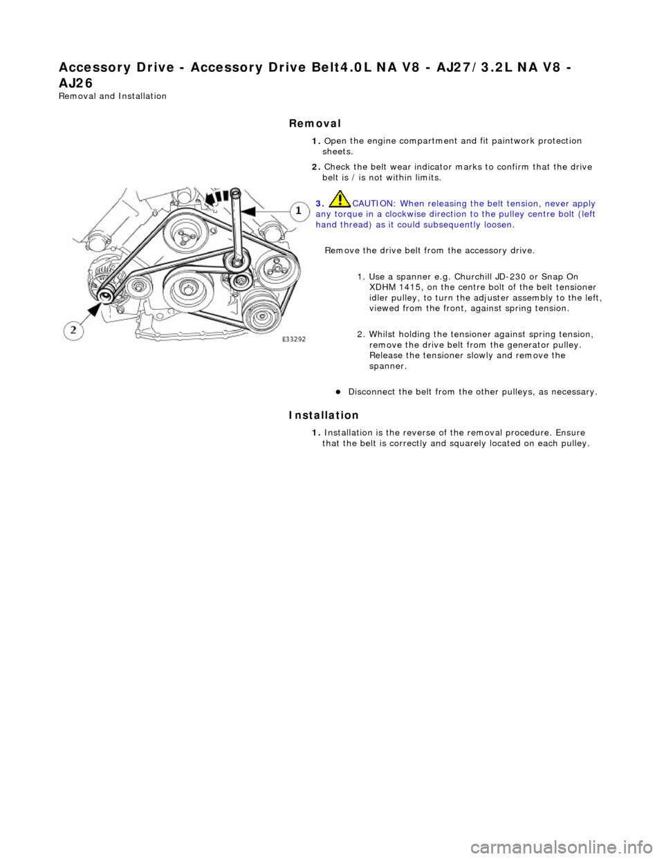
Accessory Drive - Acce
ssory
Drive Belt4.0L NA V8 - AJ27/3.2L NA V8 -
AJ26
Re
moval and Installation
Remov
al
Installation
1.
O
pen the engine compartment and fit paintwork protection
sheets.
2. Check the belt wear indicator ma rks to confirm that the drive
belt is / is not within limits.
3. CAUTI
ON: When releasing the
belt tension, never apply
any torque in a clockwise direction to the pulley ce ntre bolt (left
hand thread) as it could subsequently loosen.
Remove the drive belt fro m the accessory drive.
1. Use a spanner e.g. Churchill JD-230 or Snap On XDHM 1415, on the centre bo lt of the belt tensioner
idler pulley, to turn the adju ster assembly to the left,
viewed from the front, against spring tension.
2. Whilst holding the tensioner against spring tension, remove the drive belt from the generator pulley.
Release the tensioner sl owly and remove the
spanner.
D
isconnect the belt from the ot
her pulleys, as necessary.
1. In
stallation is the
reverse of the remova l procedure. Ensure
that the belt is correctly and sq uarely located on each pulley.
Page 1054 of 2490

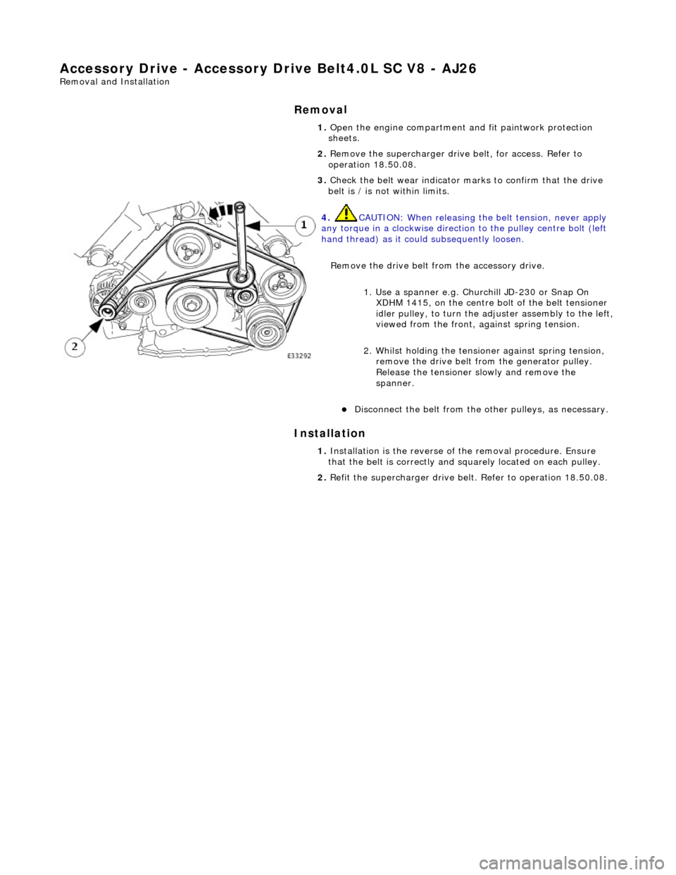
Accessory Drive - Accessory Drive Belt
4.0L SC V8 - AJ26
Re
mo
val and Installation
Remov
a
l
Installation
1.
Op
en the engine compartment and fit paintwork protection
sheets.
2. Remove the supercharger driv e belt, for access. Refer to
operation 18.50.08.
3. Check the belt wear indicator ma rks to confirm that the drive
belt is / is not within limits.
4. CAUTIO
N: When releasing the
belt tension, never apply
any torque in a clockwise direction to the pulley ce ntre bolt (left
hand thread) as it could subsequently loosen.
Remove the drive belt fro m the accessory drive.
1. Use a spanner e.g. Churchill JD-230 or Snap On XDHM 1415, on the centre bo lt of the belt tensioner
idler pulley, to turn the adju ster assembly to the left,
viewed from the front, against spring tension.
2. Whilst holding the tensioner against spring tension, remove the drive belt from the generator pulley.
Release the tensioner sl owly and remove the
spanner.
D i
sconnect the belt from the ot
her pulleys, as necessary.
1. Ins
tallation is the
reverse of the remova l procedure. Ensure
that the belt is correctly and sq uarely located on each pulley.
2. Refit the supercharger drive belt. Refer to operation 18.50.08.
Page 1181 of 2490
P
arts List
It
em
Par
t Number
De
scription
1—PI032
VVT solenoid 2
2—PI027
KS 2
3—PI004
ECT sensor
4—PI026
KS 1
5—PI031
VVT solenoid 1
6—PI035
MAFS (on vehicle)
7—PI050
Generator
8—PI040
Oil pressure switch
9—PI018
to PI021 Bank 1 Ignition coils 1 to 4
PI022 to PI025 Bank 2 Ignition coils 1 to 4
10—PI006
Throttle valve position sensor
11—PI002 En
gine management harness (on vehicle)
12—PI001 En
gine management harness (on vehicle)
13—PI033
Throttle valve motor
14—PI034
EGR valve (where fitted)
15—PI015 CM
P sensor
16—PI042
Accelerator pedal and
mechanical guard sensors
17—PI007
to PI010 Bank 1 Injectors 1 to 4 PI011 to PI014 Bank 2 Injectors 1 to 4
18—PI037
Compressor lock
sensor (where fitted)
19—PI036
Compressor clutch
20—PI017 CK
P sensor
E
ngine Harness Connectors
Location
Page 1854 of 2490
Instrument Cluster - Instrument Cluster
Description and Operation
ItemDescription
1Variable Power Steering
2Coolant Level
3Fuel Level
4Oil Pressure
5Lamp Dimmer
6Driver's Switchpack
7Generator (Charge Warning Lamp)
8Catalyst Overheat
9Instrument Cluster
10Climate Control (Signal to Module)
11ICE Head Unit