Page 849 of 2490

12. Remove the undertray. Re fer to Operation 76.22.90.
13. Remove the two bolts which se cure the generator cooling
duct to the oil pan body and remove the duct.
14. Remove the front cross member for access. Refer to
Operation 76.10.05.
15. Drain the engine oil.
1. Position the waste oil bowser.
2. Remove the drain plug from the oil pan and drain the engine oil.
Fit a new sealing washer to the drain plug.
Wipe the drain plug and install it to the oil pan to prevent
oil dripping.
Move the oil bowser away from the vehicle.
16. Remove the oil pan.
1. Remove the eighteen bolt s which secure the oil pan
to the oil pan body.
2. Remove the oil pan.
3. Remove the gasket from the oil pan body assembly.
17. Disconnect the oil cooler pipes.
1. Remove the bolt which secures the oil cooler pipes.
2. Disconnect the oil cooler pipes from the oil pan body
assembly.
3. Remove and discard the O-ring seals from the pipes
and install blanking plugs to the pipes and unions.
18. NOTE: Place a suitable container underneath filter to prevent
oil spillage.
Page 857 of 2490
Install and tighten the lower securing bolts to 18-24 Nm.
Tighten the upper securing bolts to 18-24 Nm.
16. Position the transmission cooler pipes and the clamping
bracket. Install the bolt to secu re the clamp and tighten to 7-9
Nm.
17. Connect the oil cooler pipes to the oil pan body assembly
(vehicles with engine oil cooler).
1. Remove the blanking plugs and install new O-ring seals.
2. Connect the oil cooler pipes.
3. Install the clamp and bolt which secures the oil cooler pipes. Tighten to 18-24 Nm.
18. Install the front cr ossmember. Refer to Operation 76.10.05.
19. Position the generator cooling duct to the oil pan body and
install the two bolts.
20. Install the undert ray. Refer to Operation 76.22.90.
21. Install both front wheel and tyre assemblies. Refer to
Operation 74.20.05.
22. Install the timing cover and al l associated components, as
detailed in Operation 12.65.01. Do not refill the cooling system
at this stage.
Page 906 of 2490

the pipes. Allow the oil to drain.
3. Remove the O-ring seals and fit blanking plugs to the
pipes and to the mating unions on the engine.
51. Lower the ramp.
52. Disconnect the generator suppres sion module (where fitted)
harness.
Disconnect the harness multi-plug and reposition the
harness from under the suppression module.
53. Disconnect the starter motor power cable, at the right hand
side engine compartment enclosure.
1. Disconnect the multi-plug, engine management harness to starter motor.
2. Reposition the protective boot from the starter motor
power stud.
3. Remove the nut and disc onnect the power cable.
Cut the tie strap which secures the power cable to the
enclosure and route the cable into the engine bay.
54. Disconnect the P.I. harness from the engine management
harness.
1. Release the bolt which secures the P.I. harness multi-plug to the engine management harness.
2. Disconnect the multi-plug.
3. Remove the nut which secures the engine management harness multi-plug to the mounting
bracket.
4. Reposition the multi-plug from the bracket.
55. Disconnect the transmission rota ry switch harness connector.
Reposition and disconnect the harness multi-plug.
Page 917 of 2490

WARNING: B
EFORE PROCEEDING, IT IS ESSENTIAL THAT
THE WARNING NOTES GIVEN IN SECTION 100-00 (UNDER
THE HEADING 'SAFETY PRECAUTION S') ARE READ AND UNDERSTOOD.
3.
Connect the vacuum hose to the purge valve.
30
.
Connect the fuel feed and return hoses.
R
emove the blanking plugs
from the mating pipes.
1. Connect the hoses at the Quick Fit connectors.
F
it the return hose into the feed hose clip.
31
.
Connect the starter motor power cable.
1. Reposition and connect the power cable to the power stud. Fit the securing nut to the stud.
2. Reposition the protective boot over the starter motor power stud.
3. Connect the harness connector, engine management harness to starter motor. Fit the connector to the
mounting bracket.
R
enew the tie strap which secures the power cable to the
right hand enclosure.
32
.
Connect the generator suppressi on module (where fitted)
harness.
Re
position the harn
ess under the suppression module and
connect the harness connector.
33. Connect the hoses to the power steering pump.
Page 1001 of 2490

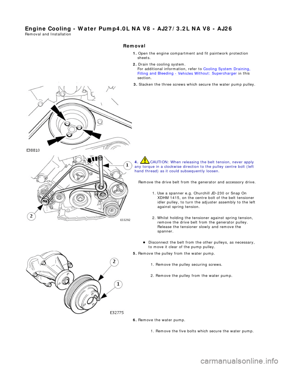
Engine Cooling - Water Pump4.0L NA V8 - AJ27/ 3.2L NA V8 - AJ26
Re
moval and Installation
Remov
al
1.
O
pen the engine compartment and fit paintwork protection
sheets.
2. Drain the cooling system.
For additional information, refer to Cooling System Draining,
Fillin
g and Bleeding
- Vehicles W
ithout: Supercharger
in
this
section.
3. Sl
acken the three screws which
secure the water pump pulley.
4. CAUTI
ON: When releasing the
belt tension, never apply
any torque in a clockwise direction to the pulley ce ntre bolt (left
hand thread) as it could subsequently loosen.
Remove the drive belt from the generator and accessory drive.
1. Use a spanner e.g. Churchill JD-230 or Snap On XDHM 1415, on the centre bo lt of the belt tensioner
idler pulley, to turn the adju ster assembly to the left
against spring tension.
2. Whilst holding the tensioner against spring tension, remove the drive belt from the generator pulley.
Release the tensioner sl owly and remove the
spanner.
D
isconnect the belt from the ot
her pulleys, as necessary,
to move it clear of the pump pulley.
5. Re
move the pulley from the water pump.
1. Remove the pulley securing screws.
2. Remove the pulley from the water pump.
6. Remove the water pump.
1. Remove the five bolts wh ich secure the water pump.
Page 1004 of 2490

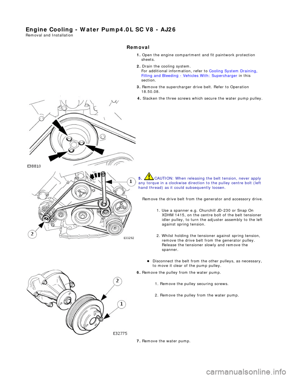
Engine Cooling - Water Pump4.0L SC V8 - AJ26
Remo
val and Installation
Remov
a
l
1.
Op
en the engine compartment and fit paintwork protection
sheets.
2. Drain the cooling system.
For additional information, refer to Cooling System Draining,
Filling and Bleedin
g
- Vehicles With
: Supercharger in this
section.
3. Remove the supercharger driv e belt. Refer to Operation
18.50.08.
4. Slacken the three screws whi
ch
secure the water pump pulley.
5. CAUTIO
N: When releasing the
belt tension, never apply
any torque in a clockwise direction to the pulley ce ntre bolt (left
hand thread) as it could subsequently loosen.
Remove the drive belt from the generator and accessory drive.
1. Use a spanner e.g. Churchill JD-230 or Snap On XDHM 1415, on the centre bo lt of the belt tensioner
idler pulley, to turn the adju ster assembly to the left
against spring tension.
2. Whilst holding the tensioner against spring tension, remove the drive belt from the generator pulley.
Release the tensioner sl owly and remove the
spanner.
Di
sconnect the belt from the ot
her pulleys, as necessary,
to move it clear of the pump pulley.
6. Remove t
he pulley from the water pump.
1. Remove the pulley securing screws.
2. Remove the pulley from the water pump.
7. Remove the water pump.
Page 1007 of 2490
W
ater Pump Pulley Vehicles Without: Supercharger
26.50.05
Removal
1. Open the engine compartment and fit paintwork protection sheets.
2
. Slacken the three screws which secure the water pump pulley.
3
.
C
AUTION:
When releasing the belt tension, never apply any torque in a clockwise direction to the pulley
centre bolt (left hand thread) as it could subsequently loosen.
Remove the drive belt from the generator and accessory drive. 1. Use a spanner e.g. Churchill JD-230 or Snap On XDHM 1415, on the centre bolt of the belt tensioner idler pulley, to turn the adjuster assembly to the left against spring tension.
Page 1008 of 2490
2.
Whilst holding the tensioner against spring tension, remove the drive belt from the generator pulley.
Release the tensioner slowly and remove the spanner.
Disconnect the belt from the other pulleys, as necessary, to move it clear of the pump pulley.
4.
Remove the pulley from the water pump.
1. remove the pulley securing screws.
2. Remove the pulley from the water pump.
Clean relevant parts and faces.
Installation
1.
Installation is the reverse of the removal procedure. Tighten the pulley securing bolts to 10-14 Nm.