Page 1692 of 2490
Fuel Tank and Lines - Fuel Tank and Li
nes
Description an
d Operation
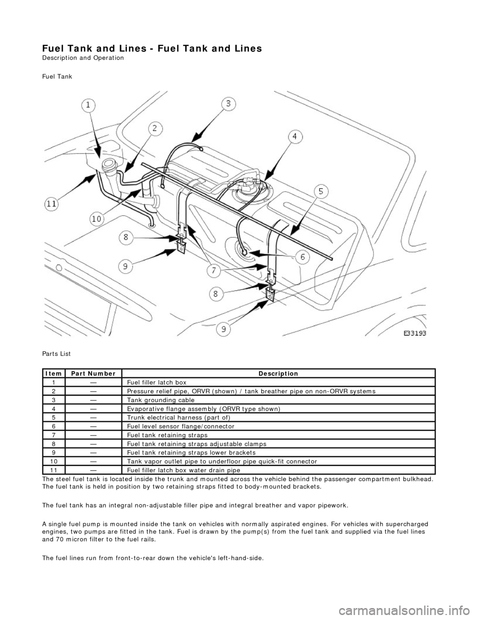
Fuel Tank
Parts List
The steel fuel tank is located inside the trunk and mounted across the vehicle behind the passenger compartment bulkhead.
The fuel tank is held in posi tion by two retaining straps fi tted to body-mounted brackets.
The fuel tank has an integral non-adjustable fill er pipe and integral breather and vapor pipework.
A single fuel pump is mounted inside the tank on vehicles with normally aspirated engines. For vehicles with supercharged
engines, two pumps are fitted in the tank. Fuel is drawn by the pump(s) from the fuel tank and supplied via the fuel lines
and 70 micron filter to the fuel rails.
The fuel lines run from front-to-rear down the vehicle's left-hand-side.
Ite
m
Part
Number
Descr
iption
1—Fu
el filler latch box
2—Pressure reli
ef pipe, ORVR
(shown) / tank breather pipe on non-ORVR systems
3—Tank grounding
cable
4—Evaporative flan
ge assembly
(ORVR type shown)
5—Trunk elec
trical harne
ss (part of)
6—Fue
l
level sensor
flange/connector
7—Fu
el tank retaining straps
8—F
u
el tank retaining stra
ps adjustable clamps
9—Fu
el tank retaining straps lower brackets
10—Tank vapor outlet pipe to un
derflo
or pipe quick-fit connector
11—F
u
el filler latch bo
x water drain pipe
Page 1737 of 2490
I
nstallation
18
.
On non-ORVR vehicles, disconnect the trunk lid lefthand strut
rear pivot.
Pl
ace a suitable support under
trunk lid or tie to exterior
mirror.
1. Using a screwdriver, release clip at rear end of strut,
withdraw end from trunk lid pivot and lower strut.
19
.
Disconnect the tank ground cable from the vehicle body.
20. Remove the tank from the vehicle.
21. Drain any remaining fuel from the tank.
1. Fit the fuel tank assembly.
2. Re
-connect the tank ground cable to the vehicle.
Tigh
ten to 12 Nm.
3. On non-ORVR fuel tanks, positi on the trunk lid lefthand strut
between the filler tube and the breather pipe.
Page 1742 of 2490
In
stallation
8.
Ro
ute the throttle cable through the water deflector bracket.
9. Ensure the drivers seat is fully rearward.
10. Remove the A-Pillar lower trim pad.
11. Di
sconnect the throttle cable from the pedal.
1. Remove the throttle cable split pin.
2. Remove the throttle cable retaining sleeve.
3. Disconnect the throttle cable.
12. From under the hood, remove the cable from the vehicle.
1. Installation is th e reverse of the re moval procedure.
Adjust th
e throttle cabl
e, refer to 19.20.08.
Page 1754 of 2490
WARNING: NEVER USE A CFC 12 ANALYZ
ER OR NAKED FLAME TYPE.
Leak tests should be carried out with a UV spot lamp or an electronic analyzer which is dedicated to HFC 134A refrigerant.
Handling Lubricati
ng Oil
Av
oid breathing lubricant mist; it can cau
s
e irritation to the respiratory system.
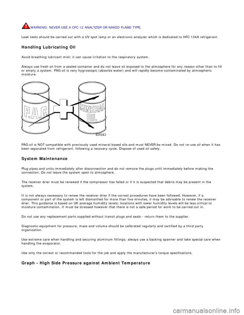
Always use fresh oil from a sealed containe r and do not leave oil exposed to the atmosphere for any reason other than to fill
or empty a system. PAG oil is very hygr oscopic (absorbs water) and will rapidly become contaminated by atmospheric
moisture.
PAG oil is NOT compatible with previously used mineral based oi ls and must NEVER be mixed. Do not re-use oil when it has
been separated from refrigerant, following a re covery cycle. Dispose of used oil safely.
System Maintenance
Plug pipes an
d units immediatel
y after disconnection an d do not remove the plugs until immediately before making the
connection. Do not leave the system open to atmosphere.
The receiver drier must be renewed if the compressor has failed or if it is susp ected that debris may be present in the
system.
It is not always necessary to renew th e receiver drier if the correct procedur es have been followed. However, if a
component or part of the system is left dismantled for more than five minutes, it may be advisable to renew the receiver
drier. This guidance is based on UK average humidity levels; lo cations with lower humidity levels will be less critical to
moisture contamination. It must be stressed however th at there is not a safe period for work to be carried out in.
Do not use any replacement parts su pplied without transit plugs and seals - return them to the supplier.
Diagnostic equipment for pres sure, mass and volume should be calibrated regularly and certified by a third party
organization.
Use extreme care when handling and securi ng aluminum fittings; always use a backing spanner and take special care when
handling the evaporator.
Use only the correct or re commended tools for the job and apply the manufacturer's torque specifications.
Graph - High S
ide Pressure against Ambient Temperature
Page 1758 of 2490
Climate Control System - General Informatio
n - Climate Control System
D
iagn
osis and Testing
I
n
troduction
It is very i
m
portant to positive
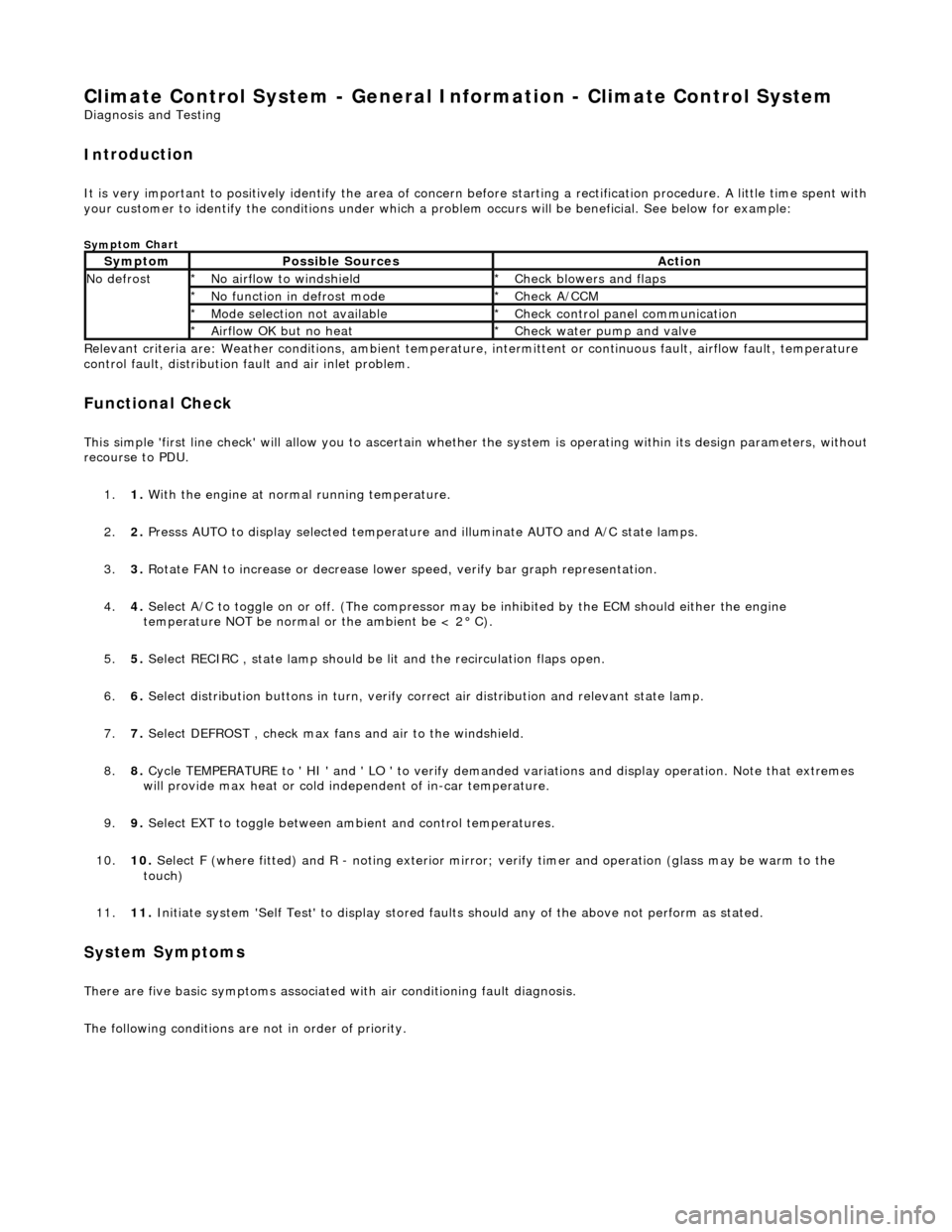
ly identify the area of concern before starting a rectification procedure. A little time spent with
your customer to identify the conditions under which a pr oblem occurs will be beneficial. See below for example:
Sym
ptom Chart
Re
lev
ant criteria are: Weather conditions,
ambient temperature, intermittent or cont inuous fault, airflow fault, temperature
control fault, distribution fault and air inlet problem.
Functio n
al Check
This
s
imple 'first line check' will allo
w you to ascertain whether the system is operating within its design parameters, withou t
recourse to PDU.
1. 1. With the engine at normal running temperature.
2. 2. Presss AUTO to display selected temperature and illuminate AUTO and A/C state lamps.
3. 3. Rotate FAN to increase or decrease lowe r speed, verify bar graph representation.
4. 4. Select A/C to toggle on or off. (T he compressor may be inhibited by the ECM should either the engine
temperature NOT be normal or the ambient be < 2° C).
5. 5. Select RECIRC , state lamp should be lit and the recirculation flaps open.
6. 6. Select distribution butt ons in turn, verify correct air distribution and relevant state lamp.
7. 7. Select DEFROST , check max fans and air to the windshield.
8. 8. Cycle TEMPERATURE to ' HI ' and ' LO ' to verify demanded variations and display operation. Note that extremes
will provide max heat or cold independent of in-car temperature.
9. 9. Select EXT to toggle between am bient and control temperatures.
10. 10. Select F (where fitted) and R - noting exterior mirror; verify timer and operation (glass may be warm to the
touch)
11. 11. Initiate system 'Self Test' to display stored faul ts should any of the above not perform as stated.
Sy
stem Symptoms
There
are five
basic symptoms associated
with air conditioning fault diagnosis.
The following conditions are not in order of priority.
Sy m
ptom
Possib
l
e Sources
Acti
o
n
N
o defrostN o
airflow to windshield
*
Check blower s and flaps
*
N o functi
on in defrost mode
*
Check A/CCM
*
Mo de s
election not available
*
Chec k
control panel communication
*
Ai rfl
ow OK but no heat
*
Check water pu
mp and valve
*
Page 1759 of 2490
Sym
ptom #2
Sy
mptom #2
Sym
ptom #3
Sy
mptom #3
No
cooling
Compressor sei
zed
Compressor seal failure
Compressor valve or piston damage
*
*
*
R
enew compressor
*
Compressor cl
utch / circuit faulty
*
R
efer to PDU
*
D
rive belt slack / broken
*
Adjust or r
enew
*
B
lower motor / circuit faulty
Pressure switch / circuit fault
*
*
R
efer to PDU
*
Total l
oss of refrigerant caused by broken pipe or joint
*
Repair / renew. Check code 2
3
*
P
artial loss of refrigerant caused by leaking joint or pipe
*
R
epair / renew, check fault code #23
*
Conden
ser damage
*
Re
new, check fault code #23
*
Bl
ocked receiver / drier filter
*
R
enew receiver / drier
*
Evaporator senso
r / circuit faulty
*
R
efer to PDU, check fault code #13
*
Bl
ocked pollen filter (if fitted)
*
Cle
an or renew
*
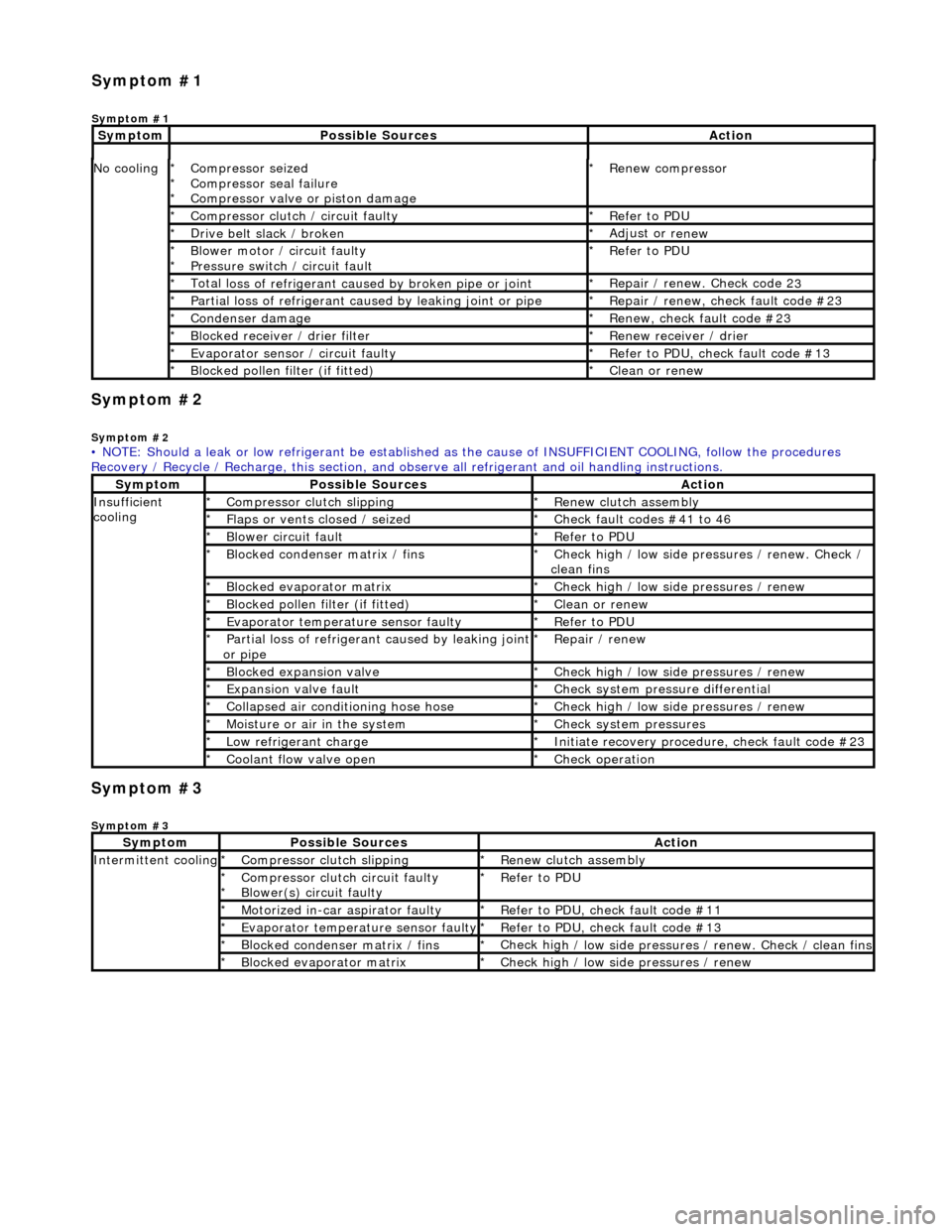
• NOTE: Should a leak or low refrigerant be established as the cause of INSUFFICIENT COOL ING, follow the procedures
Recovery / Recycle / Recharge, this section, and ob serve all refrigerant and oil handling instructions.
Sy
mptom
Possib
le Sources
Acti
on
Insuffi
cient
cooling
Compre
ssor clutch slipping
*
R
enew clutch assembly
*
Fl
aps or vents closed / seized
*
Check f
ault codes #41 to 46
*
Bl
ower circuit fault
*
R
efer to PDU
*
Bl
ocked condenser matrix / fins
*
Check hig
h / low side pr
essures / renew. Check /
clean fins
*
Bl
ocked evaporator matrix
*
Check hig
h / low side
pressures / renew
*
Bl
ocked pollen filter (if fitted)
*
Cle
an or renew
*
Evaporator temp
erat
ure sensor faulty
*
R
efer to PDU
*
P
artial loss of refrigerant caused by leaking joint
or pipe
*
R
epair / renew
*
Blocked expan
sion valve
*
Check hig
h / low side
pressures / renew
*
Expans
ion valve fault
*
Chec
k system pres
sure differential
*
C
ollapsed air conditioning hose hose
*
Check hig
h / low side
pressures / renew
*
Moi
sture or air in the system
*
Chec
k system pressures
*
Low r
efrigerant charge
*
Initiate recovery
procedure, check fault code #23
*
Coo
lant flow valve open
*
Chec
k operation
*
Sy
mptom
Possib
le Sources
Acti
on
Int
ermittent cooling
Compre
ssor clutch slipping
*
R
enew clutch assembly
*
Compressor cl
utch circuit faulty
Blower(s) circuit faulty
*
*
R
efer to PDU
*
Motorized in-car aspirator faulty
*
R
efer to PDU, check fault code #11
*
Evaporator temp
erature sensor faulty
*
R
efer to PDU, check fault code #13
*
Bl
ocked condenser matrix / fins
*
Check hig
h / low side pressures / renew. Check / clean fins
*
Bl
ocked evaporator matrix
*
Check hig
h / low side
pressures / renew
*
Sym
ptom #1
Sy
mptom #1
Sy
mptom
Possib
le Sources
Acti
on
Page 1769 of 2490
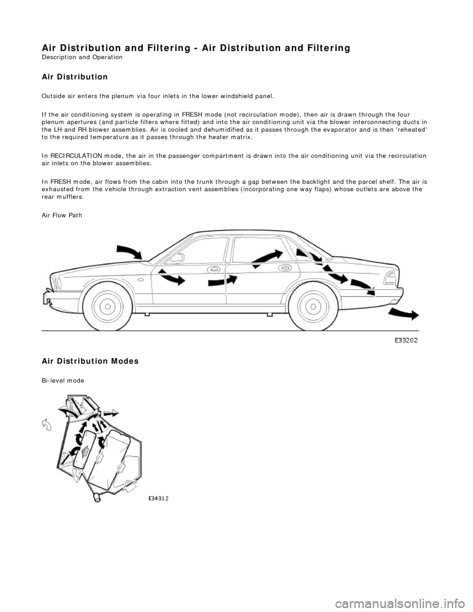
Air Distribution and Filtering - Air Distri
bution and Filtering
Description an
d Operation
Air Distribution
Ou
tside air enters the plen
um via four inlets in the lower windshield panel.
If the air conditioning system is operating in FRESH mode (not recirculation mode), then air is drawn through the four
plenum apertures (and particle filters where fitted) and into the air conditioni ng unit via the blower interconnecting ducts in
the LH and RH blower assemblies. Air is c ooled and dehumidified as it passes through the evaporator and is then 'reheated'
to the required temperature as it passes through the heater matrix.
In RECIRCULATION mode, the air in the pass enger compartment is drawn into the air conditioning unit via the recirculation
air inlets on the blower assemblies.
In FRESH mode, air flows from the cabin into the trunk through a gap between the backlight and the parcel shelf. The air is
exhausted from the vehicle through extraction vent assemblies (incorporating one way flaps) whose outlets are above the
rear mufflers.
Air Flow Path
Air Distribution Modes
Bi
-level mode
Page 1774 of 2490
I n
strument Pane
l Air Outlets
Ite
m
De
scr
iption
1Ai
r i
nlet - from RH blower (LH opposite, not shown)
2Ai
r outl
et - instrument
panel center vents
3Air ou
tlet - defog
4Ai
r outl
et - instru
ment panel LH and RH side vents
5Air outl
et - footwell
6Flap -
cool air
bypass
7Evaporator
8Matrix -
heater
Internal Components and Ai
r Fl
ow