Page 1808 of 2490

Air Conditioning - Condenser Core
Removal and Installation
Removal
1. Disconnect battery ground cable (IMPORTANT, see SRO
86.15.19 for further information).
2. Drain radiator coolant only; refer to 26.10.01 or (SC)
26.10.01.
3. Recover refrigerant from air co nditioning system; refer to
82.30.30.
4. Release both gas struts, set the engine cover fully forward to
the service access position an d support with a wooden (or
similar) strut.
5. CAUTION: Take care not to damage hood or radiator
grille.
Remove twin fan and motor as sembly; refer to 26.25.12.
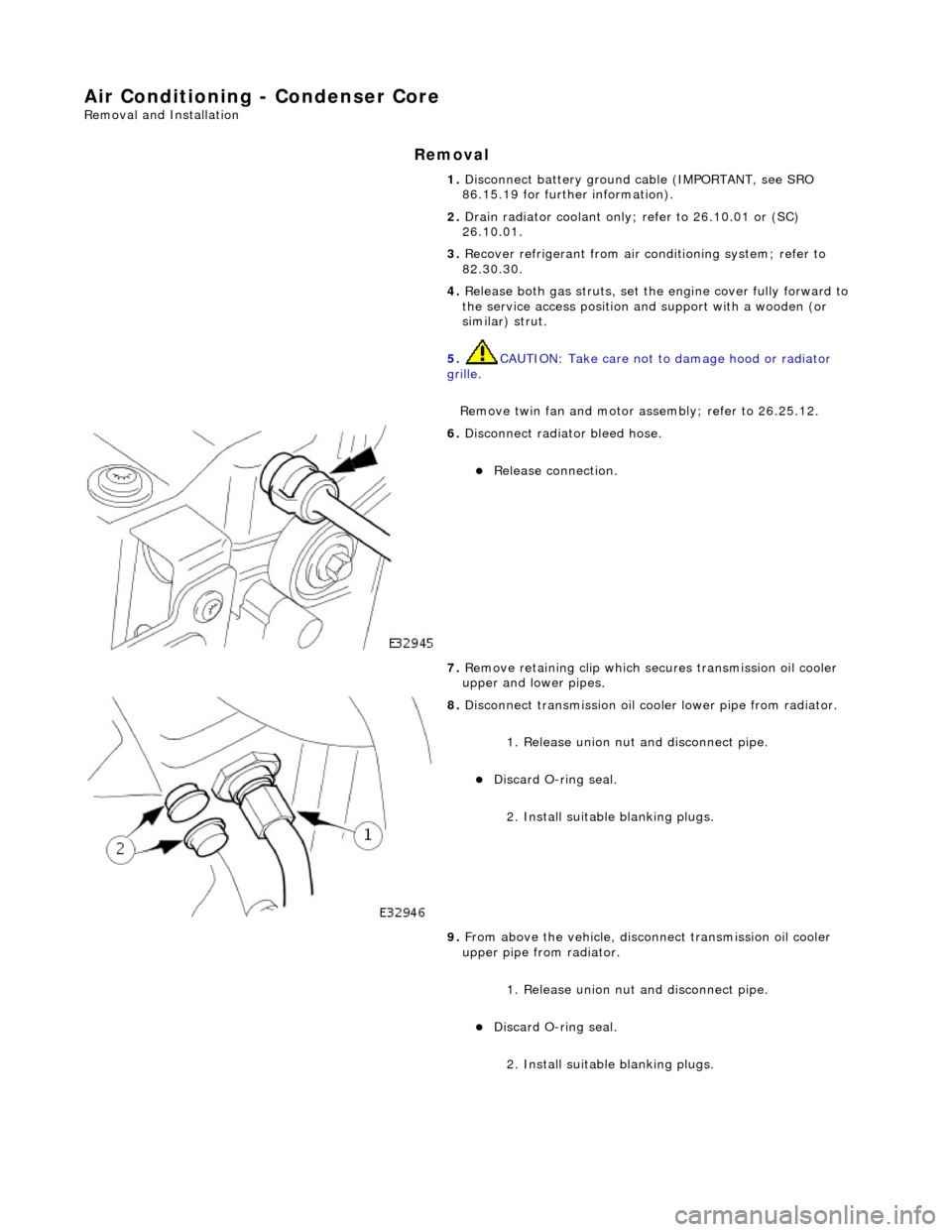
6. Disconnect radiator bleed hose.
Release connection.
7. Remove retaining clip which secures transmission oil cooler
upper and lower pipes.
8. Disconnect transmission oil cooler lower pipe from radiator.
1. Release union nut and disconne ct pipe.
Discard O-ring seal.
2. Install suitable blanking plugs.
9. From above the vehicle, discon nect transmission oil cooler
upper pipe from radiator.
1. Release union nut and disconne ct pipe.
Discard O-ring seal.
2. Install suitable blanking plugs.
Page 1811 of 2490
Installation
18. Remove radiator / condenser assembly.
Clean coolant spillage from radiator lower carrier panel.
19. Separate condenser from radiator.
1. Remove bolts.
2. Remove condenser.
20. If necessary, remove condenser to receiver / drier line from
condenser.
Remove bolt.
Detach hose from clip.
Discard O-ring seal.
Install suitable blanking plugs.
1. If necessary, renew radiator top and bottom foam sealing
strips.
Page 1813 of 2490
Connect hose.
Install bolt (8-10 Nm).
6. Connect compressor to condenser discharge line at condenser.
Remove blanking plugs.
Install new O-ring seal an d lubricate with clean A/C
compressor oil.
Connect hose.
Install bolt (8-10 Nm).
7. Connect transmission o il cooler upper pipe.
Remove blanking plugs.
Install new O-ring seal and lu bricate with clean automatic
transmission fluid.
Connect union nut to radiator and tighten.
8. Connect transmission oil cooler lower pipe.
Remove blanking plugs.
Install new O-ring seal and lu bricate with clean automatic
transmission fluid.
9. Connect radiator blee d hose to radiator.
Page 1816 of 2490
Air Conditioning - Evaporator Core
Removal and Installation
Removal
1. Remove heater / cooler unit; refer to 82.25.21.
2. Remove air conditioning control module from heater / cooler
unit.
Slacken upper fixing.
Remove lower fixings.
3. Remove evaporator pipe firewall seal plate.
Remove screws.
Remove plate.
4. Disconnect heater matrix temperature sensor.
Detach heater matrix temperature sensor connector from
unit.
Disconnect connector.
5. Remove footwell servo motor from heater / cooler unit.
Disconnect connector.
Remove screws.
Remove motor complete with bracket.
6. Disconnect evaporator sensor connector.
Page 1817 of 2490
Installation
Detach heater / cooler unit connector.
Detach evaporator sensor connector.
Disconnect connector.
7. Remove heater / cooler unit upper case from lower case.
Remove screw.
Remove 15 clips.
Remove upper case from lower case.
8. Remove evaporator from case.
Remove sensor and clip.
Remove evaporator.
1. Installation is the reverse of removal.
Page 1821 of 2490

Control Components - Control Components
Description and Operation
System Controls
The climate control system is controlled by : 1. 1. Manual input from the operator, via the center console located control panel.
2. 2. Automatically by means of the A/CCM.
Output is based upon input from the following devices:
Motorized In-car aspirator External air temperature sensor Coolant temperature sensor Heater 'air-off' (the temperature of the air leaving the matrix fins) temperature sensor Evaporator 'air-off' (the temperature of the air leaving the evaporator fins) temperature sensor Solar sensor Left hand blower recirculation / fresh air flap potentiometer Right hand blower recirculation / fresh air flap potentiometer Upper air distribution box (ADB) center and side face flap servomotor potentiometer ADB defrost flap servomotor potentiometer Air conditioning unit Foot flap servomotor potentiometer Air conditioning unit Cool Air Bypass flap servomotor potentiometer Thumbwheel controls on the facia vent assemblies which provide manu al adjustment of the airflow volume. Road and engine speed signals input to the A/CCM
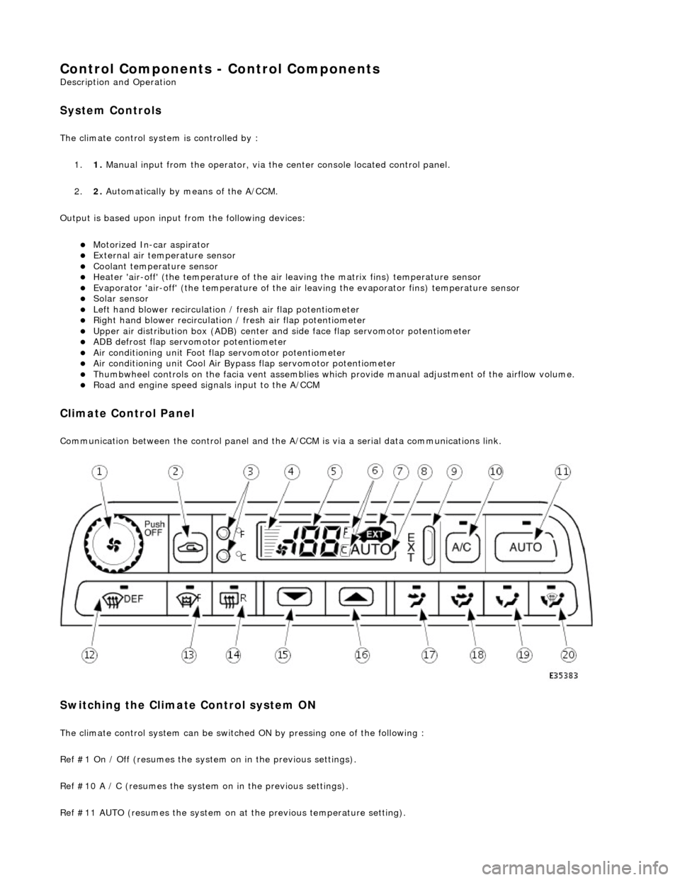
Climate Control Panel
Communication between the control panel and the A/CCM is via a serial data communications link.
Switching the Climate Control system ON
The climate control system can be switched ON by pressing one of the following :
Ref #1 On / Off (resumes the system on in the previous settings).
Ref #10 A / C (resumes the system on in the previous settings).
Ref #11 AUTO (resumes the system on at the previous temperature setting).
Page 1822 of 2490

Ref #12 DEF (resumes the system on at the previous temperature setting).
Button (switch) logic
All buttons with an integral LED state lamp conform to the following operating logic.
When the state lamp is lit the relevant func tion is operational. From this condition, pressing the button will de-activate the
function, confirmed by the LED being de-energized and the pres ence of a single audible 'beep'. A single 'beep' will
accompany the state lamp to confirm function re-selection.
1. 1. ON / OFF and manual fan speed.
Pressing this knob activates the system ON at the last settin g or switches the system OFF. Rotate the knob clockwise to
increase and anti-clockwise to decrease fan speed and thus airflow.
With the system OFF, ram air is available by the selected air di stribution mode (indicated by state lamp). Air flow will NOT
occur unless a manual air distribution mo de is selected, this air being unconditioned and flow dependent upon vehicle
speed.
• NOTE: The blowers are inhibited until the engine coolant te mperature is > 35°C, unless DEFROST, FACE or DEMIST modes
are selected.
2. 2. Manual Air Recirculation
Closes the outside air intakes of the blower asse mblies and recirculates air within the vehicle.
Two options of control are available :
Timed Recirculation. Pressing the button for less than 1.5 seconds lights up the LED (confirmed by a single bleep).
This provides recirculation of interior air for a period of approximately 5 minutes. Pressing the button within five
minutes returns the system to fresh air intake mode.
Continuous Recirculation. Pressing and holding the button for more than 1.5 seconds lights up the LED (confirmed by two beeps). This provides continuous reci rculation of interior air. Pressing the button returns the system to fresh air
intake mode.
• NOTE: Avoid using manual air recirculatio n for prolonged periods in cold weather, this may result in interior misting of
glass.
3. 3. Temperature Scale Selection
Press the appropriate button to display temperatures in degrees Celsius or Fahrenheit.
4. 4. Manual Fan Speed
Rotating the fan speed control knob (to vary fan speed) will di splay a proportional number of horizontal bars on the LCD.
There are total of eleven manual fan speeds available.
5. 5. Temperature Display
Indicator of internal demand temperatur e or external ambient temperature. The external ambient is updated every 4
seconds when the road speed > 25 km / h.
6. 6. Scale
Selected temperature scale, Celsius or Fahrenheit.
7. 7. External temperature
Symbol indicates when this option is selected
Page 1824 of 2490

External temperature < -10 °C Vehicle speed > 65 km / h The first two conditions exist > 2 minutes. Engine speed > 50 revs / min
14. 14. Heated Backlight (R)
Pressing the heated backlight button will simultaneously energize the heater elements for timed cycles of;
21 minutes backlight 11 minutes exterior mirrors
Pressing the button again within the 21 minute timer will cancel the request.
If the engine is stalled, or the ignition switched OFF, the backlight and door mirror timers will be cleared, resulting in both
functions being switched off.
• NOTE: Both the backlight and door mirrors may be activated with the climate control system OFF, but the engine must be
running.
15. 15. Temperature Decrease
Pressing this button (BLUE symbol) decreases the interior temperature setting in 1° increments. Should the button be
pressed when the setting temperature is below the lower automatic control temperature limit, the display will indicate 'LO'.
16. 16. Temperature Increase
Pressing this button (RED symbol) will raise the temperature setting in 1° increments Should the button be pressed when
the setting temperature is above the upper automatic control temperature limit, the display will indicate 'HI'.
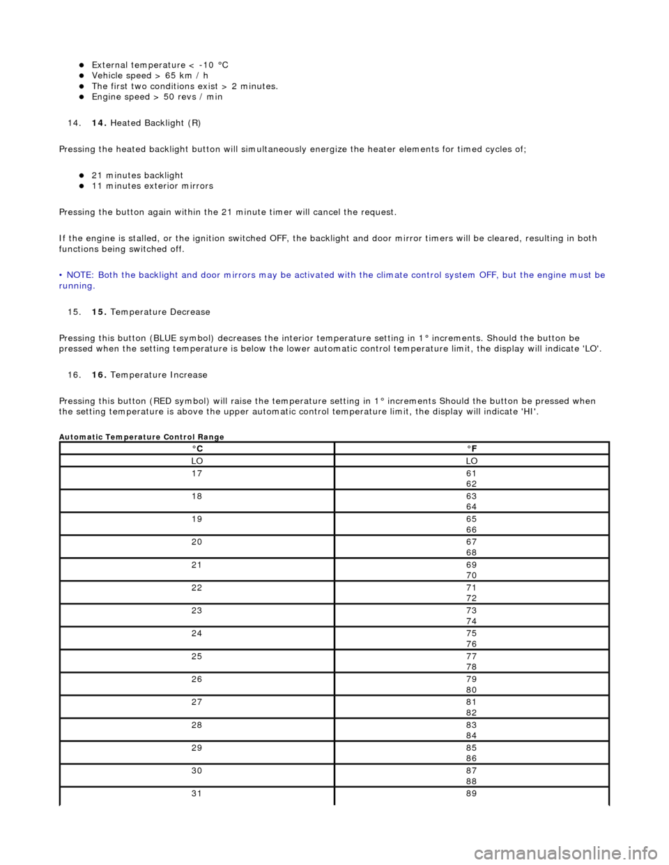
Automatic Temperature Control Range
°C°F
LOLO
1761
62
1863
64
1965
66
2067
68
2169
70
2271
72
2373
74
2475
76
2577
78
2679
80
2781
82
2883
84
2985
86
3087
88
3189